EP1609768A1 - Pièces façonnées à chaud et procédé et dispositif pour le façonnage à chaud - Google Patents
Pièces façonnées à chaud et procédé et dispositif pour le façonnage à chaud Download PDFInfo
- Publication number
- EP1609768A1 EP1609768A1 EP05011106A EP05011106A EP1609768A1 EP 1609768 A1 EP1609768 A1 EP 1609768A1 EP 05011106 A EP05011106 A EP 05011106A EP 05011106 A EP05011106 A EP 05011106A EP 1609768 A1 EP1609768 A1 EP 1609768A1
- Authority
- EP
- European Patent Office
- Prior art keywords
- article
- preform
- multi fiber
- heated
- temperature
- Prior art date
- Legal status (The legal status is an assumption and is not a legal conclusion. Google has not performed a legal analysis and makes no representation as to the accuracy of the status listed.)
- Withdrawn
Links
- 238000000034 method Methods 0.000 title claims abstract description 95
- 230000005855 radiation Effects 0.000 claims abstract description 99
- 238000010438 heat treatment Methods 0.000 claims abstract description 79
- 239000000463 material Substances 0.000 claims abstract description 44
- 230000008569 process Effects 0.000 claims abstract description 24
- 239000000835 fiber Substances 0.000 claims description 186
- 239000011521 glass Substances 0.000 claims description 56
- 230000002093 peripheral effect Effects 0.000 claims description 36
- 239000004033 plastic Substances 0.000 claims description 22
- 229920003023 plastic Polymers 0.000 claims description 22
- 238000012545 processing Methods 0.000 claims description 17
- 230000003287 optical effect Effects 0.000 claims description 13
- 239000002241 glass-ceramic Substances 0.000 claims description 6
- 239000012510 hollow fiber Substances 0.000 claims description 6
- 230000005670 electromagnetic radiation Effects 0.000 claims description 5
- 238000005253 cladding Methods 0.000 claims description 4
- 239000013307 optical fiber Substances 0.000 claims description 3
- 239000004038 photonic crystal Substances 0.000 claims description 3
- 238000003280 down draw process Methods 0.000 claims description 2
- 239000011368 organic material Substances 0.000 claims description 2
- 239000013590 bulk material Substances 0.000 claims 1
- 238000009826 distribution Methods 0.000 description 17
- 230000009102 absorption Effects 0.000 description 15
- 238000010521 absorption reaction Methods 0.000 description 15
- 230000035515 penetration Effects 0.000 description 8
- 230000000694 effects Effects 0.000 description 5
- 230000005540 biological transmission Effects 0.000 description 4
- 238000002474 experimental method Methods 0.000 description 4
- 238000012681 fiber drawing Methods 0.000 description 4
- 239000006112 glass ceramic composition Substances 0.000 description 4
- 238000009413 insulation Methods 0.000 description 4
- 238000002468 ceramisation Methods 0.000 description 3
- 238000001816 cooling Methods 0.000 description 3
- 238000000295 emission spectrum Methods 0.000 description 3
- 229910052736 halogen Inorganic materials 0.000 description 3
- 150000002367 halogens Chemical class 0.000 description 3
- 238000004519 manufacturing process Methods 0.000 description 3
- 230000007246 mechanism Effects 0.000 description 3
- 238000000926 separation method Methods 0.000 description 3
- WFKWXMTUELFFGS-UHFFFAOYSA-N tungsten Chemical compound [W] WFKWXMTUELFFGS-UHFFFAOYSA-N 0.000 description 3
- 229910052721 tungsten Inorganic materials 0.000 description 3
- 239000010937 tungsten Substances 0.000 description 3
- 230000008901 benefit Effects 0.000 description 2
- 238000002425 crystallisation Methods 0.000 description 2
- 230000008025 crystallization Effects 0.000 description 2
- 230000001419 dependent effect Effects 0.000 description 2
- 238000010891 electric arc Methods 0.000 description 2
- 238000000265 homogenisation Methods 0.000 description 2
- 238000012986 modification Methods 0.000 description 2
- 230000004048 modification Effects 0.000 description 2
- 239000007787 solid Substances 0.000 description 2
- 239000012780 transparent material Substances 0.000 description 2
- 241001589086 Bellapiscis medius Species 0.000 description 1
- 239000011358 absorbing material Substances 0.000 description 1
- 230000008859 change Effects 0.000 description 1
- 230000006378 damage Effects 0.000 description 1
- 238000013461 design Methods 0.000 description 1
- 238000011161 development Methods 0.000 description 1
- 230000002349 favourable effect Effects 0.000 description 1
- 230000005484 gravity Effects 0.000 description 1
- 230000001678 irradiating effect Effects 0.000 description 1
- 239000005304 optical glass Substances 0.000 description 1
- 238000012805 post-processing Methods 0.000 description 1
- 238000012552 review Methods 0.000 description 1
- 238000007493 shaping process Methods 0.000 description 1
- 230000003595 spectral effect Effects 0.000 description 1
- 238000001228 spectrum Methods 0.000 description 1
- 229920002994 synthetic fiber Polymers 0.000 description 1
- 230000003685 thermal hair damage Effects 0.000 description 1
- 239000013306 transparent fiber Substances 0.000 description 1
Images


Classifications
-
- C—CHEMISTRY; METALLURGY
- C03—GLASS; MINERAL OR SLAG WOOL
- C03B—MANUFACTURE, SHAPING, OR SUPPLEMENTARY PROCESSES
- C03B37/00—Manufacture or treatment of flakes, fibres, or filaments from softened glass, minerals, or slags
- C03B37/01—Manufacture of glass fibres or filaments
- C03B37/02—Manufacture of glass fibres or filaments by drawing or extruding, e.g. direct drawing of molten glass from nozzles; Cooling fins therefor
- C03B37/025—Manufacture of glass fibres or filaments by drawing or extruding, e.g. direct drawing of molten glass from nozzles; Cooling fins therefor from reheated softened tubes, rods, fibres or filaments, e.g. drawing fibres from preforms
- C03B37/028—Drawing fibre bundles, e.g. for making fibre bundles of multifibres, image fibres
-
- C—CHEMISTRY; METALLURGY
- C03—GLASS; MINERAL OR SLAG WOOL
- C03B—MANUFACTURE, SHAPING, OR SUPPLEMENTARY PROCESSES
- C03B37/00—Manufacture or treatment of flakes, fibres, or filaments from softened glass, minerals, or slags
- C03B37/01—Manufacture of glass fibres or filaments
- C03B37/012—Manufacture of preforms for drawing fibres or filaments
- C03B37/01205—Manufacture of preforms for drawing fibres or filaments starting from tubes, rods, fibres or filaments
- C03B37/01211—Manufacture of preforms for drawing fibres or filaments starting from tubes, rods, fibres or filaments by inserting one or more rods or tubes into a tube
- C03B37/01214—Manufacture of preforms for drawing fibres or filaments starting from tubes, rods, fibres or filaments by inserting one or more rods or tubes into a tube for making preforms of multifibres, fibre bundles other than multiple core preforms
-
- C—CHEMISTRY; METALLURGY
- C03—GLASS; MINERAL OR SLAG WOOL
- C03B—MANUFACTURE, SHAPING, OR SUPPLEMENTARY PROCESSES
- C03B37/00—Manufacture or treatment of flakes, fibres, or filaments from softened glass, minerals, or slags
- C03B37/01—Manufacture of glass fibres or filaments
- C03B37/012—Manufacture of preforms for drawing fibres or filaments
- C03B37/01205—Manufacture of preforms for drawing fibres or filaments starting from tubes, rods, fibres or filaments
- C03B37/01225—Means for changing or stabilising the shape, e.g. diameter, of tubes or rods in general, e.g. collapsing
- C03B37/0124—Means for reducing the diameter of rods or tubes by drawing, e.g. for preform draw-down
-
- C—CHEMISTRY; METALLURGY
- C03—GLASS; MINERAL OR SLAG WOOL
- C03B—MANUFACTURE, SHAPING, OR SUPPLEMENTARY PROCESSES
- C03B37/00—Manufacture or treatment of flakes, fibres, or filaments from softened glass, minerals, or slags
- C03B37/01—Manufacture of glass fibres or filaments
- C03B37/02—Manufacture of glass fibres or filaments by drawing or extruding, e.g. direct drawing of molten glass from nozzles; Cooling fins therefor
- C03B37/025—Manufacture of glass fibres or filaments by drawing or extruding, e.g. direct drawing of molten glass from nozzles; Cooling fins therefor from reheated softened tubes, rods, fibres or filaments, e.g. drawing fibres from preforms
- C03B37/029—Furnaces therefor
-
- C—CHEMISTRY; METALLURGY
- C03—GLASS; MINERAL OR SLAG WOOL
- C03B—MANUFACTURE, SHAPING, OR SUPPLEMENTARY PROCESSES
- C03B2205/00—Fibre drawing or extruding details
- C03B2205/02—Upward drawing
-
- C—CHEMISTRY; METALLURGY
- C03—GLASS; MINERAL OR SLAG WOOL
- C03B—MANUFACTURE, SHAPING, OR SUPPLEMENTARY PROCESSES
- C03B2205/00—Fibre drawing or extruding details
- C03B2205/60—Optical fibre draw furnaces
- C03B2205/62—Heating means for drawing
- C03B2205/63—Ohmic resistance heaters, e.g. carbon or graphite resistance heaters
-
- C—CHEMISTRY; METALLURGY
- C03—GLASS; MINERAL OR SLAG WOOL
- C03B—MANUFACTURE, SHAPING, OR SUPPLEMENTARY PROCESSES
- C03B2205/00—Fibre drawing or extruding details
- C03B2205/60—Optical fibre draw furnaces
- C03B2205/62—Heating means for drawing
- C03B2205/69—Auxiliary thermal treatment immediately prior to drawing, e.g. pre-heaters, laser-assisted resistance heaters
Definitions
- the invention relates in general to the field of hot forming articles and especially to a method of and an apparatus for hot forming of at least a part of an article, and to articles which at least in part are hot formed.
- Optical fibers or multi fiber rods may consist of glass or synthetic material as plastic, especially polymeric material, or any combination of these materials.
- hot ductile material as glass ceramic material is heated to initiate micro crystallization or ceramization processes.
- semi-transparent or transparent glasses and/or glass ceramic materials and plastics are heated up to a processing point where a viscosity ⁇ between 10 14.5 and 10 4 dPas is encountered or beyond that.
- Semi-transparent or transparent glasses and/or glass ceramics, for the setting-in of certain material properties, for example ceramization, are heated mostly to temperatures which lie preferably above the lower cooling point at a viscosity ⁇ of about 10 14.5 dPas.
- Typical, lower cooling points for glasses can be, depending on the type of glass, between 555 K and 1063 K, and typically the processing point can be up to 1978 K.
- the cooling and the processing point can be even much lower, typically being in the range of 250 K up to 580 K.
- glass or glass ceramic material has as a rule a very low heat conductivity in the range 1 W/(m K)
- glass or glass ceramic material with increasing thickness must be heated up more and more slowly in order to keep tensions in the glass or glass ceramics low. It was believed that when a homogeneous heating-up of the glass or of the glass ceramic is not achieved or is only inadequately successful, then this unfailingly would result in inhomogeneities in the process and/or in the product quality and / or in destroying the material.
- DE 42 02 944 C2 From DE 42 02 944 C2 there has become known a process and a device comprising IR radiators for the rapid heating of materials which have a high absorption above 2500 nm.
- DE 42 02 944 C2 proposes the use of a radiation converter from which secondary radiation is emitted with a wavelength range shifted into the long-wave direction with respect to the primary radiation.
- US-A-3,620,706 A heating of transparent glass homogeneous in depth with use of short-wave IR radiators is described in US-A-3,620,706.
- the process according to US-A-3,620,706 is based on the principle that the absorption length of the radiation used in glass is very much greater than the dimensions of the glass object to be heated, so that the major part of the impinging radiation is transmitted through the glass and the absorbed energy per volume is nearly equal at every point of the glass body.
- What is disadvantageous in this process is that no homogeneous irradiation over the surface of the glass objects is ensured, so that the intensity distribution of the IR radiation source is replicated on the glass to be heated.
- only a small part of the electric energy used is utilized for the heating of the glass.
- a preform which consists of multi-component transparent, semi-transparent and / or opaque glasses or plastics is heated by means of an electrical resistance heating and drawn to a fiber/multi fiber rod. If necessary, the developing fibers/fiber rods can be brought together again afterwards to build new preforms, which are again drawn to fibers/fiber rods. These new fibers/fiber rods thereby contain a multitude of the fibers/fiber rods drawn in the previous step. After several of such process steps one can get a fiber rod with several million single fibers, which can be used as image guides.
- a conventional resistance heating with temperatures of typically 1300 K at the heating coil is inadequate in this respect especially with preforms of diameters larger than 50 mm, since the emitted radiation is in a wavelength range absorbed on the surface or in layers near the surface of the glass or the plastic (penetration depth ⁇ 1 mm), the heating thereby being a surface heating.
- the inner part of the preform has to be heated completely by thermal conduction. Since glass and plastic have a poor thermal conductivity, a lot of time is needed for the heating process especially of preforms with large dimensions, because it is necessary also for the inner part of the preform to reach the temperature needed for drawing and to reduce the average temperature within the preform. Also the subsequent drawing of the fiber or rod therefore can be done only with a limited speed, since new material of the preform has to be provided and heated continuously.
- the reflected radiation hits surfaces of fibers crossed on the way to the inner region of the fiber again on the way back towards the periphery and is thereby again partly reflected, so that the effective penetration depth of the radiation into the inner region of the preform is up to 30 mm depending on the design. That means that in contradiction to the teachings of EP 1 171 392 neither is the preform completely penetrated by all of the IR radiation, so that an important amount of the radiation is reflected at the opposite wall of the radiation cavity, nor is only a small amount of the incoming radiation absorbed by the preform. Rather, an important amount of the total radiation is absorbed by the preform through multiple reflections and absorptions within the preform. A homogenous heating according to EP 1 171 392 especially of large preforms therefore is not possible.
- the invention depicts a method of hot forming of at least a part of an article, wherein said article comprises a material selected from the group consisting of transparent and semitransparent materials, wherein said at least a part of said article is heated by means of radiation and said heated part of said article is formed and whereby said heating is a semi-homogeneous heating.
- the invention further teaches an apparatus for forming at least a part of an article comprising a holding means for holding said article a heater means for heating said at least a part of the article a forming means for forming of at least said part of the article, whereby said means for heating comprises a radiation source for heating said at least part of the article, and whereby said forming means is a drawing means.
- the invention also covers articles formed according to an embodiment of the inventive method.
- said semi-homogeneous heating causes a decrease of the draw temperature being both lower at a central portion of said article and at the surface of said article compared to conventional heating methods as for instance surface heating methods as discussed before.
- semi-homogeneous heating is defined as heating at least one part or section of the article homogeneously or substantially homogeneously and at least one other part or section inhomogeneously with respect to the primary radiation source.
- Homogeneous heating may be, e.g., achieved by irradiating the part or section with radiation having a considerably larger penetration depth than the measure of the section in the direction of the incident radiation.
- Inhomogeneous heating may result from a penetration depth of the heating radiation which is lower than the dimensions of the section to be heated.
- the temperature distribution according to semi-inhomogeneous heating is at least partly homogenized due to light guiding from a homogeneously heated region with nearly uniform radiation distribution inside the section to the inhomogeneously heated section.
- a transparent material is defined herein as a material which transmits more than 50% of the impinging radiation.
- a semi-transparent material is defined as a material which transmits more than 0% but less than 50% of the impinging radiation and an opaque material as a material that transmits 0% of the radiation.
- the temperature distribution may not be entirely uniform.
- the semi-inhomogeneous heating causes an increase of temperature of the heated article being lower at a more central portion and higher at a more peripheral portion of the article.
- the more central portion is closer to the middle than the more peripheral portion.
- the central portion may, e.g., be located in the middle and the peripheral portion at the periphery of the article.
- the material of at least said part of the article consists of glass.
- the material comprises an organic material selected from the group consisting of plastic, synthetic, and polymeric material.
- the material comprises glass and a material selected from the group consisting of plastic, synthetic, and polymeric material.
- a radiation source is emitting electromagnetic radiation whereby more than 50% of the emitted radiation is in a wavelength range of 200 to 2700 nm and is a radiator having a temperature of more than 1500 K, especially having a temperature of about 3000 K.
- a most preferred forming process according to the invention is a draw process.
- the invention addresses a down-draw process and alternatively may be applied to an up-draw process.
- the invention provides a method of forming of at least a part of an article, preferably by employing a draw process, whereby the heated part of the article comprises glass and has a diameter of at least 50 mm, and whereby a temperature difference of 100 K at the most exists between a more central portion of the article and a more peripheral portion when the at least part of the article is heated.
- a method of forming of at least a part of an article preferably by employing a draw process, whereby the heated part of the article comprises glass and has a diameter of at least 50 mm, and whereby even a temperature difference of only 40 K at the most exists between a more central portion of the article and a more peripheral portion when the at least part of the article is heated.
- semi-inhomogeneous heating may also be defined as heating of an article comprising glass and having a diameter of at least 50 mm, whereby a temperature difference of 100 K, or even of only 40 K at the most exists between a more central portion of the article and a more peripheral portion.
- the temperature gradient within the heated material can be kept considerably lower compared to conventional heating methods.
- a material can be drawn with reduced maximum temperature at peripheral portions, thereby avoiding undesirable effects such as liquefying and dropping-off of peripheral portions of the heated part.
- the method is applicable within a large temperature range depending on the drawing material chosen.
- an article may be formed according to the invention with the more peripheral portion having a temperature of between 290 K and 2000 K.
- a material comprising a typical optical glass may be formed whereby a more peripheral portion of the article has a temperature of between 835 K and 915 K when the article is formed.
- Another advantage of the invention is the comparably short heat-up time coming along with semi-inhomogeneous heating.
- an article as defined above, comprising a more central portion and a more peripheral portion may be heated according to the invention so that the more peripheral portion of the heated part is heated in a period of time of less than six hours from a temperature of lower than 300 K to a temperature of higher than 890 K.
- the more peripheral portion of the heated part may be heated from a temperature of lower than 300 K to a temperature of higher than 890 K in a shorter period of time, without generating tension cracks in the material.
- the period may be less than 3 hours or even less than 1 hour.
- a rate of drawing may exceed a velocity of 10 mm per minute of the drawn part of the article relative to a clamped part of the article, the article being a multi fiber preform having a diameter of 115 mm and the drawn part having a diameter of about 25 mm or more.
- the processing of large preforms which becomes possible using the invention also allows to fabricate multi fiber rods with larger diameters.
- multi-fiber rods having diameters of greater than 25 mm, greater than 50 mm, or even greater than 79 mm may be drawn in a single drawing step.
- a multi fiber bundle having a diameter of more than 115 mm, of more than 125 mm and of more than 150 mm could be drawn to a diameter of up to 76 mm having optical grade quality.
- the inventive method as well applies to forming a multi fiber rod out of a preform with a diameter greater than 25 mm, or greater than 50 mm or even greater than 75 mm with considerable drawing speed, whereby the preform may have large diameters of more than 100 mm, of more than 125 mm or even more than 150 mm.
- an improved method of processing a multi fiber preform comprising the steps:
- the improved method enables considerably higher drawing speeds.
- the inventive method enables fast fabrication of multi fiber rods with a very large number of fibers.
- the plurality of drawn multi fiber rods may additionally be twisted.
- the plurality of drawn multi fiber rods may be twisted after the drawing step.
- Preferred articles formed at least in part by a process according to the invention comprise a fiber or a multi fiber rod.
- an article may be formed from a preform comprising a cladding tube surrounding at least in part a core of a multi fiber preform.
- inventions comprise an optical face plate, an optical inverter, an optical twister, a taper, a hollow fiber or a photonic crystal fiber, or a combination of these components.
- the invention succeeded in heating preforms of so far unknown diameters of more than 100 mm by means of a radiation unit utilizing short-wave radiation sources and walls, which have very good back scattering or reflecting properties, in a fast and semi-homogenous way and in drawing these afterwards with speeds of more than 10 mm/min and with a diameter of the drawn multi fiber rod of 25 mm whereby the preform features 115 mm in diameter.
- the effect results from the instantaneous absorption of the radiation hitting the preform in a way that only a part of less than 50 % of this radiation crosses the part of the preform, which is not tapered and may hit the preform again indirectly after reflection at the opposite wall of the radiation unit.
- the walls of the radiation unit are important for the homogenization of the radiation emitted by the radiation sources and reflected or scattered by the walls and for increasing the efficiency.
- the tapered part of the preform can be penetrated by the radiation almost completely leading to an almost homogeneous temperature distribution and homogeneous heating. Therefore, beginning from this area less tapered parts of the preform which may be heated inhomogeneously by the primary radiation sources can be heated homogeneously or nearly homogeneously by conducting the heat and/or guiding the radiation, too.
- Solid state emitters such as halogen tungsten emitters, but also gas discharge or electric-arc emitters can be utilized as radiation sources, wherein more than 50 % of the complete radiation power of each emitter shall be within the wavelength range between 200 nm and 2700 nm.
- the diameter of the preforms was between 5 mm and 115 mm, wherein these are only exemplary values with no limiting meaning in upward or downward direction.
- the preforms can either comprise only one glass or plastic in any conceivable geometry, like for instance round, square, triangular or polygonal rods and/or tubes or the like, or they can comprise several glasses or plastics, like for instance tubes of glass type 1 / plastic type 1, in and/or around which rods of glass type 2 / plastic type 2 are positioned.
- the preforms can also consist of several different single fibers / multi fiber rods put together, which can also be positioned inside a round or polyhedral tube.
- the prototype facility can continuously produce fiber rods or fibers depending on the length and the diameter of the preform. This is carried out according to the following principle:
- the pre-heating process has to be carried out once each time the facility is started up to prevent breaking of the preform 3 due to thermal tensions between the part 31 inside and the part 32 outside of the furnace 5.
- the preform is transported into the radiation unit 7.
- the preform 3 is heated by means of a ramp temperature or power controlled. This only concerns that part of the preform 3 within the radiation unit, the part outside is not heated and has a temperature at the clamping point, which is slightly above room temperature depending if this part of the preform is insulated or not.
- the preform 3 is further heated.
- the end of the preform 3 reaches a certain temperature, it is tapered due to gravity or by exerting a force with an appropriate tool and the end of the fiber cane 9, fiber 10 or multi fiber rod 11 moves downward or upward, respectively, relative to the bulk of the preform 3.
- the fiber cane 9, fiber 10 or multi fiber rod 11 has to be moved away or rolled up from the tapered section 33, so that a constant diameter of the fiber 10 or fiber cane 9 or multi fiber rod 11 is achieved.
- this facility can also be turned around by 180°, so that the fiber 10 or fiber cane 9 or multi fiber rod 11 is upwardly moved away.
- the crucial part of the facility is a radiation unit 7 with one or more heating zones built from a material, preferably quarzal, which is highly reflecting in the wavelength range of the radiation sources.
- a material preferably quarzal
- the radiators 8 may advantageously be horizontally arranged essentially omega shaped radiation elements. Alternatively or additionally, vertically arranged straight radiators and/or round discharge bulbs may be provided as radiators 8.
- the shape and arrangement of the radiators 8 may be adapted to the dimensions an shape of the radiation unit 7 and the preform 3 in order to obtain a homogeneous distribution of the radiation power.
- Separation discs (not shown in Fig. 1) having a centric bore through which the preform 3 is guided can be inserted into radiation units with multiple heating zones in order to prevent crosstalk between the zones.
- the radiation unit 7 is provided with an reflecting insulation 13 to the outside to reduce energy loss and temperature inhomogeneities.
- the insulation 13 may advantageously comprise quarzal, which is both highly reflecting and heat insulating.
- the facility 1 described above enables a semi-continuously draw of fiber canes 9 or fibers 10 or multi fiber rods 11 as desired from the preform 3.
- preforms 3 with a diameter of 115 mm have already been successfully drawn to multi fiber rods with a diameter of 25 to 76 mm.
- Fig. 2 shows emission spectra of a radiator emitting at a temperature of 1500 K and of a radiator emitting at a temperature of 3000 K and absorption characteristics of Schott Glass' 8505 Glass.
- a radiator emitting at a temperature of 3000 K emits radiation in a wavelength range of above 200 nm with maximum power at about 960 nm
- a conventional heater operated at 1500 K emits at considerably longer wavelengths above approximately 900 nm with maximum power at about 2000 nm.
- a radiator emitting at a temperature of 3000 K is more favourable, as it emits more than 50% of its power within the transparency window of the glass in the wavelength range of 200 nm to 2700 nm.
- a radiator emitting at a temperature of 3000 K a large penetration depth of the radiation can be achieved.
- Fig. 3 shows wavelength dependent re-emission, absorption and transmission characteristics of electromagnetic radiation directed to a multi fiber rod 11 drawn out from the tapered section 33 of a preform 3 as shown in Fig. 1.
- the fiber rod 11 of this example has a thickness of about 2.6 mm.
- the scale of the axis of the ordinate denotes the percental contributions of the factors re-emission, absorption and transmission to the total amount of irradiated power. Apart from the wavelength ranges around two minor absorption edges at 1900 nm and 1400 nm, the absorption amounts to approximately 20 % within the wavelength range of 500 nm to 2500 nm. Due to the small absorption of the thin fiber rod, homogeneous heating is achieved in the tapered section 33 in the region of the apex. Additionally, due to the low absorption, radiation coupled into the fibers of the fiber bundle is transported along the fibers, so that the radiation also reaches those sections of the preform which are not primarily heated homogeneously. In particular, the center portions of the non-tapered part of the preform is heated by this light guiding mechanism so that at least a partly homogenisation of the radiation distribution inside the preform is achieved.
- Fig. 4 shows a cross sectional outline in a vertical plane extending across the center of a multi fiber bundle down draw apparatus according to the invention which is suitable for execution of the inventive method utilizing semi-homogeneous heating.
- the apparatus 2 comprises holding means 17 for holding the preform 3.
- the holding means 17 is movable by means of a driving gear in order to feed the preform 3 to the furnace.
- the apparatus according to Fig. 4 comprises radiators 8 as heater means, whereby the radiators 8 preferably emit short wave IR, e.g., at a temperature of 3000 K with considerable power of more than 50 % of the total radiation power in the wavelength range of 200 nm to 2700 nm.
- the radiators 8 may be solid state emitters such as halogen tungsten emitters and/or gas discharge and/or electric-arc emitters.
- Reflective insulation walls 13 are provided to reflect transmitted or re-emitted radiation back to the preform 3.
- the furnace 5 is divided into two heating zones 19, 20 which are separated by a separation disc 15.
- the first heating zone may advantageously be used to heat the preform 3 near to the drawing temperature. Subsequently, the preform 3 which is slowly inserted by the driving gear is heated up to the drawing temperature within the second heating zone 20.
- the apparatus 2 as shown in Fig. 4 is designed as a down-draw tower. However, it may as well be constructed as an up-draw tower as shown in Fig. 5. Furthermore, the apparatus 2 may be adapted to be turned at least in part thereof by an angle of about 180° from a first angular position to a second angular position and is adapted to be used as a down draw apparatus in the first angular position and as an up draw apparatus in the second angular position.
- Drawing means are provided to exert a drawing force onto the preform in order to draw a multi fiber cane 9, multi fiber rod 11 or fiber 10 out of the preform.
- a fiber rod 11 comprising a cladding may be formed from a preform 3 comprising a cladding tube surrounding at least in part a core of a multi fiber preform.
- the drawing means of the example shown in Fig. 4 comprise motor driven drawing rollers 25.
- a motor driven reel 27 may be provided as drawing means to exert a drawing force by reeling the drawn-out fiber 10.
- a pair of clamps may be provided as means to exert a drawing force in order to draw a large diameter rod greater than 10 mm out of the preform.
- the drawing procedure is controlled by means of a control unit 21 controlling both the drawing means 25, 27 and the driving gear 23. Additionally, means for controlling the power for the radiation units and the temperature of the preform, particularly of the tapered section 33 may be provided.
- a fiber rod 11 obtained by drawing a fiber bundle preform utilizing an appparatus as shown in Fig. 4 or 5 and by employing the inventive method of semi-homogeneous heating may itself be a fiber preform for further processing, particularly for a further drawing procedure.
- the apparatus 2 as shown in Figs. 4 and 5 may advantageously be employed to process a multi fiber preform 3, whereby
- the plurality of the drawn multi fiber preforms being a multi fiber rod 11 may be twisted at or after the drawing step. Twisting of the multi fiber rod may advantageously be carried out in order to produce fiber optical inverters.
- a multi fiber rod 11 obtained by a respective drawing step may have a diameter of greater than 25 mm, greater than 50 mm, or even greater than 79 mm.
- an article obtained by employing the inventive method whereby semi-homogeneous heating is applied may comprise an optical face plate, an optical taper, a photonic crystal fiber, a hollow fiber, a hollow fiber rod, an optical fiber inverter or fiber straight-through.
- twisting the multi fiber rod 11 at or after the drawing step may advantageously applied in order to obtain a fiber optical inverter.
- the draw apparatus as shown in Figs. 4 and 5 or the facility as depicted in Fig. 1 may advantageously be adapted to work in a wide temperature range so as to enable drawing of many different materials including plastics and glass with the same apparatus.
- fiber canes 9, fibers 10 or multi fiber rods 11 may be formed using the facility 1 or the multi fiber draw apparatus 2, whereby more peripheral portions of the heated part of the preform have a temperature of between 290 K and 2000 K.
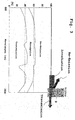
- Fig. 6 temperature distributions along a cross sectional view extending perpendicular to the longest dimension of a square shaped multi fiber bundle preform are displayed before drawing and in the course of drawing the multi fiber bundle preform.
- the temperature distributions have been photographed by means of a digital camera. Darker areas in the images indicate lower temperatures.
- radiation heating of a fiber bundle without tapered area results in a very inhomogeneous temperature distribution, whereby the temperature in the center portion of the bundle is lower than at the peripheral portion. This effects results from the low penetration depth of the radiation, although short wave infrared within the transparency window of the glass material has been applied.
- the non-tapered region of the preform is heated inhomogeneously by direct heating of the radiation sources.
- the temperature distribution shown on the left hand side is nearly homogeneous.
- This effect results from a homogeneous heating of small-diameter parts of the tapered section of the preform. These parts are heated nearly homogeneously.
- the more homogeneous temperature distribution results from radiation coupled into the homogeneously heated parts of the tapered section and guided along the fibers into the inhomogeneously heated non-tapered section of the preform.
- semi-homogeneous heating has been applied, resulting in a nearly homogeneous temperature distribution across the entire cross section of the fiber bundle.
- the temperature of a portion in the middle of the fiber bundle is lower than the temperature of a portion located at the periphery. It has been established, however, that the temperature gradient between a peripheral and a central portion within the heated part of a glass preform with a diameter of of more than 100 mm lies below 1 Kelvin per millimeter, whereby the central portion has a temperature of more than 580 K. Specifically, a preform with a diameter of 120 mm with a surface temperature or temperature of peripheral portions of about 630 K could be drawn easily using the inventive semi-homogeneous heating.
- the preform material is known to be drawable at temperatures of at least 595 K, appointing the minimum temperature at central portions of the preform.
- the preform has been heated with a temperature difference of 35 K at the most, resulting in a temperature gradient of less than 0.6 K / mm.
- the maximum preform sizes that can be drawn with conventional heating are about 60 mm in diameter. If using a preform of the same glass, a surface temperature of 715 K has been measured, resulting in a temperature gradient of about 4 K / mm.
- the remaining temperature difference between more central and more peripheral portions within fiber bundles having diameters of at least 50 mm have been estimated to be 40 K at the most, whereby peripheral portions have a temperature of between 835 K and 915 K.
- a heat-up time from a temperature of below 300 K up to more than 890 K of the peripheral portions of less than one hour could be applied without generating tension cracks. If drawing larger preforms, the heat-up period may be extended to less than 3 hours or less than six hours.
Landscapes
- Engineering & Computer Science (AREA)
- Chemical & Material Sciences (AREA)
- Life Sciences & Earth Sciences (AREA)
- General Life Sciences & Earth Sciences (AREA)
- Geochemistry & Mineralogy (AREA)
- Manufacturing & Machinery (AREA)
- Materials Engineering (AREA)
- Organic Chemistry (AREA)
- Manufacture, Treatment Of Glass Fibers (AREA)
Applications Claiming Priority (2)
| Application Number | Priority Date | Filing Date | Title |
|---|---|---|---|
| US858461 | 2004-06-01 | ||
| US10/858,461 US7832234B2 (en) | 2004-06-01 | 2004-06-01 | Hot formed articles and method and apparatus for hot-forming |
Publications (1)
| Publication Number | Publication Date |
|---|---|
| EP1609768A1 true EP1609768A1 (fr) | 2005-12-28 |
Family
ID=34936826
Family Applications (1)
| Application Number | Title | Priority Date | Filing Date |
|---|---|---|---|
| EP05011106A Withdrawn EP1609768A1 (fr) | 2004-06-01 | 2005-05-23 | Pièces façonnées à chaud et procédé et dispositif pour le façonnage à chaud |
Country Status (2)
| Country | Link |
|---|---|
| US (1) | US7832234B2 (fr) |
| EP (1) | EP1609768A1 (fr) |
Cited By (3)
| Publication number | Priority date | Publication date | Assignee | Title |
|---|---|---|---|---|
| WO2008093352A3 (fr) * | 2007-01-29 | 2009-09-24 | Sterlite Technologies Limited | Appareil et procédé pour tirer une fibre optique ayant une perte d'atténuation réduite et faible, et fibre optique produite à partir de ceux-ci |
| EP2336092A1 (fr) * | 2009-12-03 | 2011-06-22 | Shin-Etsu Chemical Co., Ltd. | Dispositif d'étirage de préforme de verre |
| CN102786221A (zh) * | 2012-08-09 | 2012-11-21 | 杭州富通通信技术股份有限公司 | 拉丝炉挡光隔热装置 |
Families Citing this family (12)
| Publication number | Priority date | Publication date | Assignee | Title |
|---|---|---|---|---|
| AU2002362489A1 (en) * | 2001-09-28 | 2003-04-14 | Schott Glas | Method and device for shaping a structured body and body produced according to said method |
| DE102009008318A1 (de) * | 2009-02-10 | 2010-08-12 | Krones Ag | Vorrichtung zum Erhitzen von Kunststoffvorformlingen |
| DE102011103686B4 (de) | 2010-06-18 | 2016-07-14 | Schott Ag | Verfahren und Vorrichtung zur Herstellung einer mikrostrukturierten Faser mittels Hybridheiztechnik |
| US9822580B2 (en) * | 2011-02-22 | 2017-11-21 | Guardian Glass, LLC | Localized heating techniques incorporating tunable infrared element(s) for vacuum insulating glass units, and/or apparatuses for same |
| ES2538980T3 (es) * | 2011-07-12 | 2015-06-25 | Sms Concast Italia S.P.A. | Dispositivo para transferir un material metalúrgico |
| RU2530477C2 (ru) * | 2013-01-18 | 2014-10-10 | Федеральное государственное бюджетное учреждение науки Научный центр волоконной оптики Российской академии наук (НЦВО РАН) | Способ изготовления микроструктурированных волоконных световодов |
| US8768128B1 (en) * | 2013-01-22 | 2014-07-01 | Ofs Fitel, Llc | Color coded optical fibers |
| KR101853035B1 (ko) | 2013-12-23 | 2018-04-27 | 헤래우스 쿼츠 아메리카 엘엘씨 | 불투명한 석영 유리 부품을 형성하기 위한 방법 |
| JP2017511897A (ja) | 2014-02-17 | 2017-04-27 | ショット アクチエンゲゼルシャフトSchott AG | フォトニック結晶ファイバ、特に赤外線波長領域用のシングルモードファイバ及びフォトニック結晶ファイバの製造方法 |
| WO2018112386A1 (fr) | 2016-12-16 | 2018-06-21 | Schott Corporation | Compositions de chalcogénure pour fibres optiques et autres systèmes |
| US11028004B2 (en) * | 2017-02-26 | 2021-06-08 | Anatoly Glass, Llc | Twisted glass canes for artists |
| US12528729B2 (en) | 2023-06-08 | 2026-01-20 | Owens-Brockway Glass Container Inc. | Low-temperature glass container blowing process |
Citations (3)
| Publication number | Priority date | Publication date | Assignee | Title |
|---|---|---|---|---|
| FR2267987A1 (en) * | 1974-04-19 | 1975-11-14 | Haussonne Jean Marie | Drawing optical waveguides - using blank rendered partly translucent to allow heating by focused radiation or by lasers |
| FR2606866A1 (fr) * | 1986-11-17 | 1988-05-20 | Centre Nat Rech Scient | Procede et four pour le chauffage d'un materiau et application au chauffage d'une preforme en vue de realiser son etirage sous la forme d'une fibre |
| WO2002000559A2 (fr) * | 2000-06-21 | 2002-01-03 | Schott Glas | Dispositif pour chauffer de maniere homogene des verres et/ou des vitroceramiques |
Family Cites Families (4)
| Publication number | Priority date | Publication date | Assignee | Title |
|---|---|---|---|---|
| US3620706A (en) | 1967-11-20 | 1971-11-16 | Owens Illinois Inc | Method of thermal tempering transparent glass bodies |
| DE4202944C2 (de) | 1992-02-01 | 1994-07-14 | Heraeus Quarzglas | Verfahren und Vorrichtung zum Erwärmen eines Materials |
| AU3557500A (en) | 1999-03-23 | 2000-10-09 | Fotheringham, Ulrich | Method and device for the homogeneous heating of glass and/or glass-ceramic articles using infrared radiation |
| US20030056546A1 (en) * | 2001-09-18 | 2003-03-27 | Claus Richard O. | Photonic crystal materials and devices |
-
2004
- 2004-06-01 US US10/858,461 patent/US7832234B2/en not_active Expired - Fee Related
-
2005
- 2005-05-23 EP EP05011106A patent/EP1609768A1/fr not_active Withdrawn
Patent Citations (3)
| Publication number | Priority date | Publication date | Assignee | Title |
|---|---|---|---|---|
| FR2267987A1 (en) * | 1974-04-19 | 1975-11-14 | Haussonne Jean Marie | Drawing optical waveguides - using blank rendered partly translucent to allow heating by focused radiation or by lasers |
| FR2606866A1 (fr) * | 1986-11-17 | 1988-05-20 | Centre Nat Rech Scient | Procede et four pour le chauffage d'un materiau et application au chauffage d'une preforme en vue de realiser son etirage sous la forme d'une fibre |
| WO2002000559A2 (fr) * | 2000-06-21 | 2002-01-03 | Schott Glas | Dispositif pour chauffer de maniere homogene des verres et/ou des vitroceramiques |
Cited By (4)
| Publication number | Priority date | Publication date | Assignee | Title |
|---|---|---|---|---|
| WO2008093352A3 (fr) * | 2007-01-29 | 2009-09-24 | Sterlite Technologies Limited | Appareil et procédé pour tirer une fibre optique ayant une perte d'atténuation réduite et faible, et fibre optique produite à partir de ceux-ci |
| EP2336092A1 (fr) * | 2009-12-03 | 2011-06-22 | Shin-Etsu Chemical Co., Ltd. | Dispositif d'étirage de préforme de verre |
| CN102786221A (zh) * | 2012-08-09 | 2012-11-21 | 杭州富通通信技术股份有限公司 | 拉丝炉挡光隔热装置 |
| CN102786221B (zh) * | 2012-08-09 | 2014-09-24 | 杭州富通通信技术股份有限公司 | 拉丝炉挡光隔热装置 |
Also Published As
| Publication number | Publication date |
|---|---|
| US20050274149A1 (en) | 2005-12-15 |
| US7832234B2 (en) | 2010-11-16 |
Similar Documents
| Publication | Publication Date | Title |
|---|---|---|
| US7832234B2 (en) | Hot formed articles and method and apparatus for hot-forming | |
| US20240190754A1 (en) | Method for fabricating an optical fibre preform | |
| JP4554085B2 (ja) | ガラスセラミック部材、及び/又はガラス部材を製造する方法 | |
| US20080202167A1 (en) | Thermal edge finishing | |
| JP4312365B2 (ja) | 透明プラスチック線状体の製造方法 | |
| JP2011012954A (ja) | 赤外線を用いたガラス及び/又はガラスセラミックを均一に加熱するための方法及び装置 | |
| CN107337339B (zh) | 生产高折射薄玻璃基板的方法 | |
| RU2245851C2 (ru) | Способ и устройство для равномерного прогревания стекол и/или стеклокерамики с помощью инфракрасного излучения | |
| US11840472B2 (en) | Elongation method and preform for producing an optical glass component | |
| DE10029522A1 (de) | Vorrichtung zum homogenen Erwärmen von Gläsern und/oder Glaskeramiken | |
| KR20130117784A (ko) | 강화된 유리 봉입부 및 방법 | |
| JP3531567B2 (ja) | 閃光照射加熱装置 | |
| CN106392337A (zh) | 一种对射式多焦点激光分离脆性透射材料方法及装置 | |
| CN112645587A (zh) | 光学纤维锥及其加工装置和加工方法 | |
| CN115304283B (zh) | 一种C-Lens玻璃、毛坯制备方法、拉丝机 | |
| JP2000319031A (ja) | 光ファイバプリフォームの火炎研磨方法 | |
| JP7591509B2 (ja) | 横断面が変化するガラス光導波路 | |
| JP4759624B2 (ja) | プラスチック光ファイバの製造方法 | |
| JP6824233B2 (ja) | 石英ガラス製品及び石英ガラス光学部材の形成方法 | |
| CN115734952A (zh) | 玻璃材料的改性方法 | |
| CN119126297A (zh) | 数值孔径可调的耦合用光纤传像元件的制备方法及其应用 | |
| CN118524916A (zh) | 一种光纤面板的熔压模具,光纤面板及其熔压方法和应用 | |
| JPS63156021A (ja) | 光学素子の成形方法 | |
| JPH04352106A (ja) | ガラス製光発散素子の製造方法 | |
| JPH04358102A (ja) | ガラス製光発散素子の製造方法 |
Legal Events
| Date | Code | Title | Description |
|---|---|---|---|
| PUAI | Public reference made under article 153(3) epc to a published international application that has entered the european phase |
Free format text: ORIGINAL CODE: 0009012 |
|
| 17P | Request for examination filed |
Effective date: 20050613 |
|
| AK | Designated contracting states |
Kind code of ref document: A1 Designated state(s): AT BE BG CH CY CZ DE DK EE ES FI FR GB GR HU IE IS IT LI LT LU MC NL PL PT RO SE SI SK TR |
|
| AX | Request for extension of the european patent |
Extension state: AL BA HR LV MK YU |
|
| 17Q | First examination report despatched |
Effective date: 20060710 |
|
| AKX | Designation fees paid |
Designated state(s): DE FR GB |
|
| STAA | Information on the status of an ep patent application or granted ep patent |
Free format text: STATUS: EXAMINATION IS IN PROGRESS |
|
| STAA | Information on the status of an ep patent application or granted ep patent |
Free format text: STATUS: THE APPLICATION IS DEEMED TO BE WITHDRAWN |
|
| 18D | Application deemed to be withdrawn |
Effective date: 20180710 |