EP1610029A1 - Dispositif de regulation de vibrations - Google Patents
Dispositif de regulation de vibrations Download PDFInfo
- Publication number
- EP1610029A1 EP1610029A1 EP04723401A EP04723401A EP1610029A1 EP 1610029 A1 EP1610029 A1 EP 1610029A1 EP 04723401 A EP04723401 A EP 04723401A EP 04723401 A EP04723401 A EP 04723401A EP 1610029 A1 EP1610029 A1 EP 1610029A1
- Authority
- EP
- European Patent Office
- Prior art keywords
- vibration
- pressure
- chamber
- equilibrium chamber
- liquid chamber
- Prior art date
- Legal status (The legal status is an assumption and is not a legal conclusion. Google has not performed a legal analysis and makes no representation as to the accuracy of the status listed.)
- Withdrawn
Links
- 239000007788 liquid Substances 0.000 claims abstract description 104
- 230000001360 synchronised effect Effects 0.000 claims abstract description 30
- 238000005192 partition Methods 0.000 claims description 21
- 230000000694 effects Effects 0.000 description 8
- 230000006837 decompression Effects 0.000 description 7
- 230000006866 deterioration Effects 0.000 description 6
- 230000005489 elastic deformation Effects 0.000 description 3
- 230000004044 response Effects 0.000 description 2
- 230000004043 responsiveness Effects 0.000 description 2
- 238000007789 sealing Methods 0.000 description 2
- 238000013016 damping Methods 0.000 description 1
- 238000007599 discharging Methods 0.000 description 1
- 230000009189 diving Effects 0.000 description 1
- 238000009434 installation Methods 0.000 description 1
- 239000000463 material Substances 0.000 description 1
- 210000002445 nipple Anatomy 0.000 description 1
Images


Classifications
-
- F—MECHANICAL ENGINEERING; LIGHTING; HEATING; WEAPONS; BLASTING
- F16—ENGINEERING ELEMENTS AND UNITS; GENERAL MEASURES FOR PRODUCING AND MAINTAINING EFFECTIVE FUNCTIONING OF MACHINES OR INSTALLATIONS; THERMAL INSULATION IN GENERAL
- F16F—SPRINGS; SHOCK-ABSORBERS; MEANS FOR DAMPING VIBRATION
- F16F13/00—Units comprising springs of the non-fluid type as well as vibration-dampers, shock-absorbers, or fluid springs
- F16F13/04—Units comprising springs of the non-fluid type as well as vibration-dampers, shock-absorbers, or fluid springs comprising both a plastics spring and a damper, e.g. a friction damper
- F16F13/26—Units comprising springs of the non-fluid type as well as vibration-dampers, shock-absorbers, or fluid springs comprising both a plastics spring and a damper, e.g. a friction damper characterised by adjusting or regulating devices responsive to exterior conditions
- F16F13/264—Units comprising springs of the non-fluid type as well as vibration-dampers, shock-absorbers, or fluid springs comprising both a plastics spring and a damper, e.g. a friction damper characterised by adjusting or regulating devices responsive to exterior conditions comprising means for acting dynamically on the walls bounding a working chamber
Definitions
- the present invention relates to a vibration-proof apparatus which is employed for general industrial machines, for example, especially for automobiles or the like, and which can absorb and damp vibration transmitted from a vibration-generating portion such as an engine to a vibration-receiving portion such as a frame.
- An engine mount as a vibration-proof apparatus, is disposed between an engine and a vehicle body (frame) of an automobile.
- the engine mount absorbs vibration energy by an internal resistance or the like of a rubber elastic body, damps vibration from the engine, and suppresses vibration transmitted to the frame.
- the engine as the vibration-generating portion is used under a variety of driving conditions ranging from an idling driving state to a driving state at a maximum engine speed, so that frequency of vibration generated from the engine is changed over a wide range. Therefore, the engine mount should be suitable for a wide range of frequency.
- the vibration-proof apparatus disclosed in the document 1 comprises a diaphragm for structuring a portion of a partition of a pressure-receiving liquid chamber, an air chamber (equilibrium chamber) which is disposed adjacent to the pressure-receiving liquid chamber through the diaphragm, and switching valves for communicating the equilibrium chamber with a negative pressure supply source and an atmospheric pressure supply source, alternately, wherein the switching valves are controlled such that negative pressure and atmospheric pressure are introduced alternately into the equilibrium chamber in synchronous with the inputted vibration, and the pressure and the volume of the equilibrium chamber are changed in synchronous with the inputted vibration. Accordingly, the change of the volume of the equilibrium chamber allows the change of the liquid pressure generated by the inputted vibration within the pressure-receiving liquid chamber to be actively controlled and absorbed.
- an object of the present invention is to provide a vibration-proof apparatus which, even when vibration having high frequency is applied thereto, is able to alternately introduce negative pressure and an atmospheric pressure into the equilibrium chamber in synchronous with the inputted vibration with sufficiently high accuracy thus making it possible to prevent earlier occurrences of failure and deterioration of switching valves for introducing negative pressure and atmospheric pressure alternately into the equilibrium chamber.
- the first aspect of the present invention is the vibration-proof apparatus comprising, a first mounting member which is connected to one of a vibration-generating portion and a vibration-receiving portion, a second mounting member which is connected to the other of the vibration-generating portion and the vibration-receiving portion, an elastic body which is disposed between the first mounting member and the second mounting member and which is elastically deformed due to inputted vibration from the vibration-generating portion, a pressure-receiving liquid chamber whose partition is partially formed by the elastic body and whose internal volume expands or contracts due to the deformation of the elastic body, a sub-liquid chamber which communicates with the pressure-receiving liquid chamber through a limiting path such that liquid can flow mutually between the pressure-receiving liquid chamber and the sub-liquid chamber, a movable partition portion which forms a part of the partition of the pressure-receiving liquid chamber, and which is movably supported in a direction in which the internal volume of the pressure-receiving liquid chamber expands or contracts, an equilibrium
- an elastic body is disposed between a first mounting member and a second mounting member, and is elastically deformed when inputting of vibration from the vibration-generating portion, by this, the inputted vibration is damped and absorbed by the internal resistance of the elastic body, at the same time, liquid can flow mutually through a limiting path between a pressure-receiving liquid chamber and a sub-liquid chamber each having the internal volume changing in accordance with the elastic deformation of the elastic body, whereby vibration can be absorbed and damped by liquid viscosity resistance and liquid column resonance.
- the control means controls N switching valves which are connected to the equilibrium chamber to be synchronized with the inputted vibration from the vibration-generating portion to successively and selectively operate one switching valve of the N switching valves, and to alternately introduce negative pressure and atmospheric pressure, through the selected switching valve, into the equilibrium chamber.
- the internal pressure (atmospheric pressure) of the equilibrium chamber is changed so that the internal volume is also changed. Due to the change of the volume of the equilibrium chamber, the change (raise) of liquid pressure that occurs during the inputting of vibration within the pressure-receiving liquid chamber can be absorbed, and the raise of a dynamic spring constant can be suppressed, whereby the inputted vibration can be absorbed and damped more effectively.
- the cycle for operating each switching valve can be extended (made longer) by about N times. Consequently, if an appropriate number of switching valves to be equipped is determined in accordance with the maximum value of the frequency of the inputted vibration from the vibration-generating portion, even when vibration having high frequency is applied to the apparatus, the operational cycle of each switching valve can be sufficiently long.
- the second aspect of the present invention is the vibration-proof apparatus comprising a first mounting member which is connected to one of a vibration-generating portion and a vibration-receiving portion, a second mounting member which is connected to the other of the vibration-generating portion and the vibration-receiving portion, an elastic body which is disposed between the first mounting member and the second mounting member and which is elastically deformed due to inputted vibration from the vibration-generating portion, a pressure-receiving liquid chamber whose partition is partially formed by the elastic body and whose internal volume expands or contracts due to the deformation of the elastic body, a sub-liquid chamber which communicates with the pressure-receiving liquid chamber through a limiting path such that liquid can flow mutually between the pressure-receiving liquid chamber and the sub-liquid chamber, a movable partition portion which forms a part of a partition of the sub-liquid chamber, and which is movably supported in a direction in which the internal volume of the sub-liquid chamber expands or contracts, an equilibrium chamber which is disposed adjacent to the
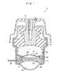
- a vibration-proof apparatus according to a first embodiment of the present invention is shown in Figs. 1 and 2.
- a vibration-proof apparatus 10 is employed as an engine mount in which an engine as a vibration-generating portion in a car is supported to a vehicle body as a vibration-receiving portion.
- the vibration-proof apparatus 10 comprises a connecting fitting 12 which is connected to an engine using bolts (not shown), a holder 14 which is connected to a vehicle body side, and an elastic body 16, which is disposed between the connecting fitting 12 and the holder 14, and serves as a vibration-absorbing main body against vibration transmitted from an engine.
- the elastic body 16 is made of a rubber material, and integrally connected to the connecting fitting 12 by means of vulcanizing-adhesion or the like.
- a pressure-receiving liquid chamber 18 whose inner wall is partially formed by the elastic body 16 and which seals therein a liquid
- a first sub-liquid chamber 22 which is connected, through a first orifice 20 as a limiting path, to the pressure-receiving liquid chamber 18, an equilibrium chamber 24 which is provided, through a first diaphragm 26, at a portion of the pressure-receiving liquid chamber 18 and whose internal volume is expandable/contractible, and an air chamber 30 which is provided, through a second diaphragm 28, at an underside of the first sub-liquid chamber 22 and into which air is introduced all the time.
- the pressure-receiving liquid chamber 18 and the first sub-liquid chamber 22 are partitioned by a disk-shaped divider 32 therebetween.
- the vibration-proof apparatus 10 also has a communicating path 34 which penetrates through the divider 32, has one end which is open toward the equilibrium chamber 24, and has the other end which is open toward the exterior of the holder 14.
- the other end of the communicating path 34 is connected, through a nipple (not shown), to one end portion of a pressure pipe 36 comprising a pipe, a pressure-resistance hose and the like.
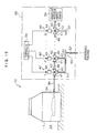
- the vibration-proof apparatus 10 has a pressure-switching unit 38 at the exterior of the holder 14, and the pressure-switching unit 38 is connected, through the communicating path 34 and the pressure pipe 36, to the equilibrium chamber 24.
- the pressure-switching unit 38 has N switching valves 40 (N is an integer of 2 or more), and each of N switching valves 40 is structured to be of a three-port type in which a first port 41 is selectively communicated with either one of a second port 42 and a third port 43. Further, each switching valve 40 comprises a valve body for switching the second port 42 or the third port 43 to be communicated with the first port 41, and an electromagnetic solenoid 44 for driving the valve body.
- the second port 42 and the first port 41 are connected with each other in series by a connecting pipe 46, the first port 41 in the first switching valve 40 is connected to the other end portion of the pressure pipe 36, and the second port 42 in the N-numbered switching valve 40 is open to atmosphere through a serial pipe 48.
- the third port 43 in each of the N switching valves 40 is connected to a parallel pipe 50, and connected to a negative pressure supply source 54 in parallel for supplying negative pressure lower than atmospheric pressure.
- the parallel pipe 50 comprises branch portions 51 which are branched into N at one end side of the parallel pipe and a collecting portion 52 at which the N-branched branch portions 51 are combined into one at the other end side thereof.
- the N-branch portions 51 are respectively connected to the third ports 43 in the N switching valves 40, and the collecting portion 52 is connected to the negative pressure supply source 54.
- the negative pressure supply source 54 is structured by a surge tank in a sucking path for sucking air into an engine or a vacuum tank connected to this surge tank.
- the pressure-switching unit 38 has a controller 56 for controlling the N switching valves 40.
- the controller 56 outputs a driving signal as a control signal selectively to one of the N switching valves 40.
- the switching valve 40 switches a communication object of the first port 41 from the second port 42 to the third port 43. Further, when no driving signal is inputted from the controller 56, the switching valve 40 holds a state in which the first port 41 is communicated with the second port 42.
- the controller 56 when the controller 56 outputs a driving signal to an arbitrary switching valve 40, the first port 41 is communicated with the third port 43 in the switching valve 40. At this time, in each of the remaining switching valves 40, since the first port 41 is communicated with the second port 42, negative pressure is supplied into the equilibrium chamber 24, through this switching valve 40 to which the driving signal is inputted, and switching valves 40 which are disposed at the equilibrium chamber 24 side with respect to this switching valve 40 and connected serially by the connecting pipes 46. Further, when a driving signal which has been applied to an arbitrary switching valve 40 is turned off by the controller 56, in all of the switching valves 40, the first ports 41 are communicated with the second ports 42.
- FIG. 9 an example of a conventional vibration-proof apparatus 100 having therein one switching valve 102 for alternately introducing negative pressure and atmospheric pressure into an equilibrium chamber is shown for the comparison with the vibration-proof apparatus 10 of the present embodiment. Since the internal structure of the vibration-proof apparatus 100 comprising a pressure-receiving liquid chamber, a sub-liquid chamber, an orifice, an equilibrium chamber 112 and the like is fundamentally structured in the same manner as in the vibration-proof apparatus 10 according to the present embodiment, a description thereof will be omitted.
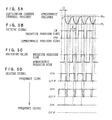
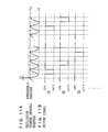
- Figs. 3(A) and 3(B) show a timing chart illustrating a relationship between a driving signal outputted from a controller 104 to one switching valve 102 and an internal pressure of the equilibrium chamber 112 in the vibration-proof apparatus 100 shown in Fig. 9, and Figs. 4(A) and 4(B) show a timing chart illustrating a relationship between driving signals which are successively outputted from the controller 56 to N switching valves 40, and the internal pressure of the equilibrium chamber 24 in the vibration-proof apparatus 10 according to the present embodiment. ;
- the timing chart shown in Figs. 3(A) and 3(B) shows a case in which, when vibration having frequency F is inputted from the vibration-generating portion to the conventional vibration-proof apparatus 100, the controller 104 controls the switching valve 102 to alternately introduce negative pressure and atmospheric pressure into the equilibrium chamber 112 in synchronous with the inputted vibration having frequency F.
- the timing chart shown in Figs. 4(A) and 4(B) illustrates a case in which, when vibration having frequency F is inputted from the vibration-generating portion to the vibration-proof apparatus 10 according to the present embodiment, in synchronous with the inputted vibration having frequency F, the controller 56 controls N switching valves 40 successively to introduce negative pressure and atmospheric pressure into the equilibrium chamber 24.
- the controller 104 when vibration having frequency F is inputted thereto, as shown in Fig. 3(B), the controller 104 outputs a driving signal to an electromagnetic solenoid 111 of one switching valve 102 at the cycle of 1/F over a predetermined decompression time T. Therefore, negative pressure is supplied from the negative pressure supply source 54, through the switching valve 102, to the equilibrium chamber 112. Decompressing of the internal pressure of the equilibrium chamber 112 from pressure P H which is slightly lower than atmospheric pressure begins. At this point, as shown in Fig.
- the internal pressure of the equilibrium chamber 112 is decompressed so as to be approximated to the negative pressure which is supplied from the negative pressure supply source 54, i.e., the internal pressure (vacuum pressure) within the negative pressure supply source 54, to reach pressure P L that corresponds to the vacuum pressure and the decompression time T. Further, a certain delay time D occurs from the time when the controller 104 outputs a driving signal to the switching valve 102 till the time when the switching valve 102 completes a port switching operation.
- the controller 104 controlling single switching valve 102, as shown in Fig. 3(A), the internal pressure within the equilibrium chamber 112 is changed so as to draw a substantially wavy waveform between the pressure P H and the pressure P L .
- the change of the internal volume in accordance with the change of the internal pressure within the equilibrium chamber 112 is synchronized with the inputted vibration, due to the change of the internal volume of the equilibrium chamber 112, change of liquid pressure that occurs during the inputting of vibration within the pressure-receiving liquid chamber can be absorbed, whereby the inputted vibration can be absorbed and damped effectively.
- the cycle at which the controller 56 outputs a driving signal to arbitrary one switching valve 40 is N/F.
- a driving signal is outputted at the cycle which is N times as much as the cycle of 1/F at which a driving signal is outputted to the switching valve 102 in the conventional vibration-proof apparatus 10.
- the controller 56 selects one switching valve 40 from N switching valves 40 successively (e.g., 1st, 2nd... N-numbered, 1st....), and outputs a driving signal to the selected switching valve 40 over a predetermined decompression time T.
- the controller 56 controlling N switching valves 40 as described above, the internal pressure of the equilibrium chamber 24 is changed so as to draw a substantially wavy waveform between the pressure P H and the pressure P L .
- the change of the internal volume in accordance with that of the internal pressure within the equilibrium chamber 24 is supposed to be synchronized with the inputted vibration, the change of liquid pressure in the pressure-receiving liquid chamber 18 that occurs when vibration is inputted can be absorbed due to the change of internal volume of the equilibrium chamber 24, and the inputted vibration can be absorbed and damped effectively.
- the operation cycle of one switching valve 40 becomes N times as much as that in the case. Therefore, it is natural that the number of times of operations of one switching valve 40 become 1/N times the operational frequency of the switching valve 102. Accordingly, in accordance with the vibration-proof apparatus 10 of the present embodiment, as compared to the conventional vibration-proof apparatus 100, the occurrence of machine failure due to failures of the switching valves 40 can be suppressed, whereby machine life can be extended much longer.
- Timing chart of Figs. 5(A), (B), (C) and (D) shows a relationship between a driving signal outputted from the controller 104 to one switching valve 102, an internal pressure of the equilibrium chamber 112, and a port switching state of the switching valve 102 in the conventional vibration-proof apparatus 100 when vibration having a comparatively high frequency F is inputted thereto.
- the delay time D is required for a first port 108 of the switching valve 102 to finish switching from a second port 109 at an atmospheric pressure side to a third port 110 at the negative supply source 54 side.
- the internal pressure of the equilibrium chamber 112 becomes unable to be increased to the level of the pressure P H substantially close to the atmospheric pressure, the difference between the pressure P H and the pressure P L is reduced, whereby effects due to damping with respect to the inputted vibration using the vibration-proof apparatus 100 is also deteriorated.
- Fig. 5(D) shows the change of a driving signal (duty ratio) outputted from the controller 104 to the switching valve 102 in the case in which the frequency F of the inputted vibration is gradually increased.
- the higher the frequency F the larger the duty ratio, and finally, the duty ratio becomes 100%.
- the first port 108 of the switching valve 102 is kept in connection with the third port 110 at the negative pressure supply source 54 side, and the internal pressure of the equilibrium chamber 112 is maintained at a constant pressure P L .
- the delay time D in the switching valve 102 is not more than the operational cycle 1/F, the duty ratio of a driving signal becomes 100% thus disabling the switching operation of the switching valve 102.
- Figs. 6(A), 6(B), and 6(C) show a timing chart illustrating a relationship among driving signals which are successively outputted from the controller 56 to N switching valves 40, the internal pressure of the equilibrium chamber 24, and the port switching state of the switching valve 40 in the vibration-proof apparatus 10 according to the present embodiment when vibration having relatively high frequency F is inputted thereto.
- the duty ratio of a driving signal with respect to arbitrary one switching valve 40 becomes 1/N times as much as that in the conventional vibration-proof apparatus 100.
- the vibration-proof apparatus 10 due to elastic deformation of the elastic body 16 when inputting of vibration from the engine as the vibration-generating portion, the inputted vibration is damped and absorbed by the internal resistance of the elastic body 16. Simultaneously, liquid can flow mutually, through the first orifice 20, between the pressure-receiving liquid chamber 18 and the first sub-chamber 22 each having the internal volume which is changed in accordance with the elastic deformation of the elastic body 16. Consequently, due to the operations of viscosity resistance and liquid column resonance of the liquid, vibration can be absorbed and damped.
- the controller 56 controls N switching valves 40 which are connected to the equilibrium chamber 24 to be synchronized with the inputted vibration from the vibration-generating portion to successively and selectively operate one switching valve 40 of the N switching valves 40, and to alternately introduce negative pressure and atmospheric pressure, through the selected switching valve 40, into the equilibrium chamber 24. Accordingly, in synchronous with the inputted vibration, the internal pressure (atmospheric pressure) of the equilibrium chamber 24 is changed so that the internal volume is also changed.
- the change (raise) of liquid pressure that occurs during the inputting of vibration within the pressure-receiving liquid chamber 18 can be absorbed, and the raise of a dynamic spring constant can be suppressed, whereby the inputted vibration can be absorbed and damped more effectively.
- N switching valves 40 are connected to the equilibrium chamber 24, the cycle for operating each switching valve 40 can be extended by about N times as long as the cycle in the case in which one switching valve is provided. Consequently, if the number of switching valves to be equipped is appropriately determined in accordance with the maximum value of frequency F of the inputted vibration from the engine, for example, during the application of vibration having high frequency F, since the operation cycles of the respective switching valves 40 can be set a sufficiently long time, negative pressure and atmospheric pressure can be introduced alternately into the equilibrium chamber 24 in synchronous with the inputted vibration with high accuracy. Further, the operation of the switching valves 40 at a higher speed than their capacity is not required, and the number of times of operations itself of each switching valve 40 can be reduced, whereby earlier occurrences of failure and deterioration of the switching valves 40 can be prevented effectively.
- N switching valves 40 are connected to the equilibrium chamber 24 in series, there is a concern that, due to the increase of installation numbers of the switching valves 40, the switching valves 40 unexpectedly play a role of air-supplying/discharging resistance whereby a phenomenon occurs in which introduction of negative pressure and atmospheric pressure into the equilibrium chamber 40 is blocked. For this reason, it is advisable that N switching valves 40 are connected to the equilibrium chamber 24 in parallel, or, N switching valves 40 are divided into some groups such that the switching valves 40 in each group are connected to each other in series and the switching valves 40 belonging to these groups are connected to the equilibrium chamber 24 in parallel.
- Fig. 10 shows a variant example of a pressure-switching unit in the vibration-proof apparatus according to the first embodiment of the present invention.
- the negative pressure supply source 54 is connected to the tip end of the serial pipe 48, and the tip end of the collecting portion 52 of the parallel pipe 50 is open to the atmosphere.
- Figs. 11(A) and 11(B) show a timing chart of a relationship between the driving signal, which are outputted from the controller 56 to each switching valve 40 and the internal pressure of the equilibrium chamber 24 in the case in which the pressure-switching unit 39 having the above-described structure is adopted.
- the controller 56 uses on/off output patterns of driving signals outputted to the respective switching valves 40, which patterns are obtained by reversing those in the case where the pressure-switching unit 38 as shown in Fig. 2.
- the controller 56 must switch off the driving signal outputted to one switching valve 40 selected from N switching valves 40 over the time T at the cycle of N/F, whereby atmospheric pressure is introduced, through the switching valve 40 having the driving signal switched-off, into the equilibrium chamber 24.
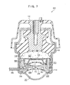
- Figs. 7 and 8 show a vibration-proof apparatus according to a second embodiment of the present invention.
- a vibration-proof apparatus 60 is also employed as an engine mount for supporting the engine as the vibration-generating portion in a car to a vehicle body as the vibration-receiving portion.
- portions identical to those in the vibration-proof apparatus 10 according to the first embodiment of the present invention are denoted by the same reference numerals and a description thereof will be omitted.
- the vibration-proof apparatus 60 is different from the vibration-proof apparatus 10 according to the first embodiment of the present invention in that a second sub-liquid chamber 62 is additionally provided in the holder 14, and an equilibrium chamber 68 is disposed adjacent to the second sub-liquid chamber 62.
- a dividing member 64 for defining the pressure-receiving liquid chamber 18 and the second sub-liquid chamber 62 is disposed in the holder 14.
- the dividing member 64 is provided with a second orifice 66 as a limiting path connecting the pressure-receiving liquid chamber 18 and the second sub-liquid chamber 64.
- a third diaphragm 70 for defining the second sub-liquid chamber 62 and the equilibrium chamber 68 is fixed between the dividing member 64 and the divider 32.
- the third diaphragm 70 is elastically deformable in a direction in which the internal volumes of the second sub-liquid chamber 62 and the equilibrium chamber 68 expand or contract.
- the pressure-switching unit 38 is connected, through the communication path 34 and the pressure pipe 36, to the equilibrium chamber 68. Therefore, the pressure-switching unit 38 is synchronized with the inputted vibration to alternately introduce negative pressure and atmospheric pressure into the equilibrium chamber 68 whereby the internal volume of the equilibrium chamber 24 is changed, and the liquid pressure within the second sub-liquid chamber 62 adjacent to the equilibrium chamber 68 through the third diaphragm 70 can be changed.
- the change of the liquid pressure of the second sub-liquid chamber 62 is transmitted, through the second orifice 66, to the pressure-receiving liquid chamber 18.
- the vibration-proof apparatus 60 according to the present embodiment, as the internal pressure (atmospheric pressure) of the equilibrium chamber 68 is changed in synchronous with the inputted vibration, the internal volume thereof is changed, and as the volume of the equilibrium chamber 68 is changed, the liquid pressure of the second sub-liquid chamber 62 is changed.
- the switching valves 40 are synchronized with the inputted vibration with high accuracy to alternately introduce negative pressure and atmospheric pressure into the equilibrium chamber 24. Further, the operation of the switching valves 40 at a higher speed than their capacity is not needed, and the number of times of operations itself of each switching valve 40 can be reduced, whereby the occurrences of earlier failure and deterioration on the switching valves 40 can be prevented effectively.
- the third diaphragm 70 forms a part of a partition of the second sub-liquid chamber 62, and the equilibrium chamber 68 is disposed adjacent to the second sub-liquid 62 through the third diaphragm 70, if the cross-section and the length of the second orifice 66 connecting the pressure-receiving chamber 18 and the second sub-liquid chamber 62 are determined (tuned) in accordance with the vibration frequency that is desired to be absorbed particularly effectively, the change of liquid pressure in the second sub-liquid chamber 62 due to the alternate introduction of negative pressure and atmospheric pressure into the equilibrium chamber 68 can be amplified by means of a resonance effect of the liquid flowing through the second orifice 66, and transmitted to the pressure-receiving liquid chamber 18, whereby the inputted vibration having the specified frequency can be absorbed and damped particularly effectively.
Landscapes
- Engineering & Computer Science (AREA)
- General Engineering & Computer Science (AREA)
- Mechanical Engineering (AREA)
- Combined Devices Of Dampers And Springs (AREA)
Applications Claiming Priority (3)
| Application Number | Priority Date | Filing Date | Title |
|---|---|---|---|
| JP2003087059 | 2003-03-27 | ||
| JP2003087059A JP4437892B2 (ja) | 2003-03-27 | 2003-03-27 | 防振装置 |
| PCT/JP2004/004219 WO2004085874A1 (fr) | 2003-03-27 | 2004-03-25 | Dispositif de regulation de vibrations |
Publications (2)
| Publication Number | Publication Date |
|---|---|
| EP1610029A1 true EP1610029A1 (fr) | 2005-12-28 |
| EP1610029A4 EP1610029A4 (fr) | 2006-07-05 |
Family
ID=33095089
Family Applications (1)
| Application Number | Title | Priority Date | Filing Date |
|---|---|---|---|
| EP04723401A Withdrawn EP1610029A4 (fr) | 2003-03-27 | 2004-03-25 | Dispositif de regulation de vibrations |
Country Status (4)
| Country | Link |
|---|---|
| US (1) | US20060125162A1 (fr) |
| EP (1) | EP1610029A4 (fr) |
| JP (1) | JP4437892B2 (fr) |
| WO (1) | WO2004085874A1 (fr) |
Families Citing this family (5)
| Publication number | Priority date | Publication date | Assignee | Title |
|---|---|---|---|---|
| WO2010050521A1 (fr) * | 2008-10-28 | 2010-05-06 | 株式会社ブリヂストン | Procédé de fabrication d’un dispositif antivibratoire |
| US8960654B2 (en) * | 2009-07-28 | 2015-02-24 | Bridgestone Corporation | Vibration isolation device |
| JP5868794B2 (ja) * | 2012-06-22 | 2016-02-24 | 京セラ株式会社 | 触感呈示装置 |
| FR3028965B1 (fr) * | 2014-11-21 | 2018-03-02 | Dav | Dispositif de retour haptique pour vehicule automobile |
| CN120724258B (zh) * | 2025-08-20 | 2026-01-02 | 国网江西省电力有限公司南昌供电分公司 | 高空作业安全带危险状态智能监测方法、系统及电子设备 |
Family Cites Families (5)
| Publication number | Priority date | Publication date | Assignee | Title |
|---|---|---|---|---|
| JP2862776B2 (ja) * | 1993-10-26 | 1999-03-03 | 財団法人鉄道総合技術研究所 | 流量制御方法および装置 |
| JPH11230245A (ja) * | 1998-02-10 | 1999-08-27 | Tokai Rubber Ind Ltd | 空気圧加振式の能動型制振器 |
| JP3700556B2 (ja) * | 2000-07-31 | 2005-09-28 | 東海ゴム工業株式会社 | 空気圧式能動型防振装置 |
| JP3780835B2 (ja) * | 2000-09-14 | 2006-05-31 | 東海ゴム工業株式会社 | 能動型流体封入式防振装置 |
| JP2002174288A (ja) * | 2000-12-05 | 2002-06-21 | Tokai Rubber Ind Ltd | 空気圧式能動型防振装置 |
-
2003
- 2003-03-27 JP JP2003087059A patent/JP4437892B2/ja not_active Expired - Fee Related
-
2004
- 2004-03-25 WO PCT/JP2004/004219 patent/WO2004085874A1/fr not_active Ceased
- 2004-03-25 EP EP04723401A patent/EP1610029A4/fr not_active Withdrawn
- 2004-03-25 US US10/550,763 patent/US20060125162A1/en not_active Abandoned
Non-Patent Citations (2)
| Title |
|---|
| No further relevant documents disclosed * |
| See also references of WO2004085874A1 * |
Also Published As
| Publication number | Publication date |
|---|---|
| JP2004293667A (ja) | 2004-10-21 |
| US20060125162A1 (en) | 2006-06-15 |
| EP1610029A4 (fr) | 2006-07-05 |
| WO2004085874A1 (fr) | 2004-10-07 |
| JP4437892B2 (ja) | 2010-03-24 |
Similar Documents
| Publication | Publication Date | Title |
|---|---|---|
| US9719575B2 (en) | Vibration-damping device | |
| JP2002031184A (ja) | 流体封入式防振装置 | |
| US6902156B2 (en) | Pneumatically operated active vibration damping device | |
| EP1610029A1 (fr) | Dispositif de regulation de vibrations | |
| US6722641B2 (en) | Liquid filled type vibration isolator | |
| JP2004069005A (ja) | 流体封入式防振装置 | |
| JP2590034B2 (ja) | 防振装置 | |
| EP1036952B1 (fr) | Isolateur anti-vibrations elasto-hydraulique | |
| KR101753788B1 (ko) | 능동제어식 엔진마운트 | |
| JPH10184775A (ja) | 液体封入式防振装置 | |
| JPH11166578A (ja) | 防振装置 | |
| JP3545458B2 (ja) | 防振システム | |
| JP3087134B2 (ja) | 切替型の液体封入式防振装置 | |
| JP2007315446A (ja) | エンジンマウント装置 | |
| JP3700610B2 (ja) | 空気圧制御式防振装置 | |
| JP3586810B2 (ja) | 液体封入式防振装置 | |
| JP2005024008A (ja) | 防振装置 | |
| JP3533243B2 (ja) | 防振装置 | |
| JP2006300163A (ja) | 防振装置 | |
| JPS62127538A (ja) | 振動体支持装置 | |
| JP2005036842A (ja) | 防振装置 | |
| JP3659091B2 (ja) | 流体封入式防振装置 | |
| JP4233791B2 (ja) | 防振装置 | |
| JP2003222184A (ja) | 防振装置 | |
| JP3554981B2 (ja) | 液体封入式防振装置 |
Legal Events
| Date | Code | Title | Description |
|---|---|---|---|
| PUAI | Public reference made under article 153(3) epc to a published international application that has entered the european phase |
Free format text: ORIGINAL CODE: 0009012 |
|
| 17P | Request for examination filed |
Effective date: 20051005 |
|
| AK | Designated contracting states |
Kind code of ref document: A1 Designated state(s): AT BE BG CH CY CZ DE DK EE ES FI FR GB GR HU IE IT LI LU MC NL PL PT RO SE SI SK TR |
|
| AX | Request for extension of the european patent |
Extension state: AL LT LV MK |
|
| A4 | Supplementary search report drawn up and despatched |
Effective date: 20060607 |
|
| DAX | Request for extension of the european patent (deleted) | ||
| RBV | Designated contracting states (corrected) |
Designated state(s): DE FR |
|
| 17Q | First examination report despatched |
Effective date: 20070717 |
|
| STAA | Information on the status of an ep patent application or granted ep patent |
Free format text: STATUS: THE APPLICATION IS DEEMED TO BE WITHDRAWN |
|
| 18D | Application deemed to be withdrawn |
Effective date: 20090221 |