EP1610043A1 - Fluidventil - Google Patents
Fluidventil Download PDFInfo
- Publication number
- EP1610043A1 EP1610043A1 EP05013585A EP05013585A EP1610043A1 EP 1610043 A1 EP1610043 A1 EP 1610043A1 EP 05013585 A EP05013585 A EP 05013585A EP 05013585 A EP05013585 A EP 05013585A EP 1610043 A1 EP1610043 A1 EP 1610043A1
- Authority
- EP
- European Patent Office
- Prior art keywords
- valve
- fluid
- valve body
- grooves
- fluid valve
- Prior art date
- Legal status (The legal status is an assumption and is not a legal conclusion. Google has not performed a legal analysis and makes no representation as to the accuracy of the status listed.)
- Granted
Links
Images
Classifications
-
- F—MECHANICAL ENGINEERING; LIGHTING; HEATING; WEAPONS; BLASTING
- F16—ENGINEERING ELEMENTS AND UNITS; GENERAL MEASURES FOR PRODUCING AND MAINTAINING EFFECTIVE FUNCTIONING OF MACHINES OR INSTALLATIONS; THERMAL INSULATION IN GENERAL
- F16K—VALVES; TAPS; COCKS; ACTUATING-FLOATS; DEVICES FOR VENTING OR AERATING
- F16K5/00—Plug valves; Taps or cocks comprising only cut-off apparatus having at least one of the sealing faces shaped as a more or less complete surface of a solid of revolution, the opening and closing movement being predominantly rotary
- F16K5/06—Plug valves; Taps or cocks comprising only cut-off apparatus having at least one of the sealing faces shaped as a more or less complete surface of a solid of revolution, the opening and closing movement being predominantly rotary with plugs having spherical surfaces; Packings therefor
- F16K5/0605—Plug valves; Taps or cocks comprising only cut-off apparatus having at least one of the sealing faces shaped as a more or less complete surface of a solid of revolution, the opening and closing movement being predominantly rotary with plugs having spherical surfaces; Packings therefor with particular plug arrangements, e.g. particular shape or built-in means
-
- F—MECHANICAL ENGINEERING; LIGHTING; HEATING; WEAPONS; BLASTING
- F16—ENGINEERING ELEMENTS AND UNITS; GENERAL MEASURES FOR PRODUCING AND MAINTAINING EFFECTIVE FUNCTIONING OF MACHINES OR INSTALLATIONS; THERMAL INSULATION IN GENERAL
- F16K—VALVES; TAPS; COCKS; ACTUATING-FLOATS; DEVICES FOR VENTING OR AERATING
- F16K27/00—Construction of housing; Use of materials therefor
- F16K27/06—Construction of housing; Use of materials therefor of taps or cocks
- F16K27/067—Construction of housing; Use of materials therefor of taps or cocks with spherical plugs
-
- F—MECHANICAL ENGINEERING; LIGHTING; HEATING; WEAPONS; BLASTING
- F16—ENGINEERING ELEMENTS AND UNITS; GENERAL MEASURES FOR PRODUCING AND MAINTAINING EFFECTIVE FUNCTIONING OF MACHINES OR INSTALLATIONS; THERMAL INSULATION IN GENERAL
- F16K—VALVES; TAPS; COCKS; ACTUATING-FLOATS; DEVICES FOR VENTING OR AERATING
- F16K47/00—Means in valves for absorbing fluid energy
- F16K47/08—Means in valves for absorbing fluid energy for decreasing pressure or noise level and having a throttling member separate from the closure member, e.g. screens, slots, labyrinths
-
- F—MECHANICAL ENGINEERING; LIGHTING; HEATING; WEAPONS; BLASTING
- F16—ENGINEERING ELEMENTS AND UNITS; GENERAL MEASURES FOR PRODUCING AND MAINTAINING EFFECTIVE FUNCTIONING OF MACHINES OR INSTALLATIONS; THERMAL INSULATION IN GENERAL
- F16K—VALVES; TAPS; COCKS; ACTUATING-FLOATS; DEVICES FOR VENTING OR AERATING
- F16K5/00—Plug valves; Taps or cocks comprising only cut-off apparatus having at least one of the sealing faces shaped as a more or less complete surface of a solid of revolution, the opening and closing movement being predominantly rotary
- F16K5/06—Plug valves; Taps or cocks comprising only cut-off apparatus having at least one of the sealing faces shaped as a more or less complete surface of a solid of revolution, the opening and closing movement being predominantly rotary with plugs having spherical surfaces; Packings therefor
- F16K5/0626—Easy mounting or dismounting means
- F16K5/0642—Easy mounting or dismounting means the spherical plug being insertable from one and only one side of the housing
-
- F—MECHANICAL ENGINEERING; LIGHTING; HEATING; WEAPONS; BLASTING
- F16—ENGINEERING ELEMENTS AND UNITS; GENERAL MEASURES FOR PRODUCING AND MAINTAINING EFFECTIVE FUNCTIONING OF MACHINES OR INSTALLATIONS; THERMAL INSULATION IN GENERAL
- F16K—VALVES; TAPS; COCKS; ACTUATING-FLOATS; DEVICES FOR VENTING OR AERATING
- F16K5/00—Plug valves; Taps or cocks comprising only cut-off apparatus having at least one of the sealing faces shaped as a more or less complete surface of a solid of revolution, the opening and closing movement being predominantly rotary
- F16K5/06—Plug valves; Taps or cocks comprising only cut-off apparatus having at least one of the sealing faces shaped as a more or less complete surface of a solid of revolution, the opening and closing movement being predominantly rotary with plugs having spherical surfaces; Packings therefor
- F16K5/0663—Packings
- F16K5/0668—Single packings
Definitions
- the invention relates to a fluid valve consisting of a Valve body and a valve body according to the preamble of claim 1
- This fluid valve in particular to shut off hydraulic or pneumatic lines known.
- This fluid valve consists of a valve housing with embedded valve seat and a valve body in Shape of a sphere.
- This ball has a through hole on, the two connections of the valve body depending on Can connect position of the valve body with each other.
- This spherical valve body of the Passage cross section By turning the spherical valve body of the Passage cross section gradually reduced to zero so that this type of valve as a metering valve at the same time can be used.
- this has a transverse to the through hole Groove into which engages a pin.
- This Spigot is connected with a handle.
- the groove allows a safe torque transfer from the handle on the valve body. Since the groove through the axis of rotation of Valve body runs, but this can in no way Regulate the flow of fluid through the valve.
- This fluid valve has proven itself many times in practice and forms the starting point of the present invention.
- the invention is based on the object, a fluid valve of the type mentioned above, which is characterized by a sensitive adjustability of the flowing through Fluid quantity is distinguished.
- the fluid valve according to claim 1 is used in particular for Adjusting a fluid flow for hydraulic or pneumatic motors a vehicle drive. It consists of one Valve housing and a rotatably mounted therein valve body, preferably up to incorporated fluid channels formed substantially rotationally symmetrical is. Preferably, the valve body is substantially spherically formed.
- the valve body has a Through hole through, through the two connections of the valve body be connected with each other communicatively can. If this through hole comes with appropriate Valve seats within the valve housing to cover, so results in the maximum possible cable cross-section for the fluid.
- the fluid valve sets the fluid in this Position contrary to the lowest possible flow resistance. Due to the symmetry of this valve body occurs the same situation in a 180 ° rotated position of the valve body.
- the fluid valve according to the invention is advantageous, because in this way in both extreme positions of the valve body the maximum possible fluid flow is given, while using it in a middle position of the valve body perpendicular to the terminals extending through hole blocks the fluid flow.
- the fluid valve can in this way advantageous for metering the fluid flow used both for forward and reverse become.
- the through-hole has the disadvantage that the valve body, the fluid flow in a relative large adjustment angle range locks. This leads to the preferred Use case, the control of vehicle drive motors to the unpleasant effect that the traction motors when retracting the throttle lever relatively quickly Block what corresponds to a full braking while driving.
- the grooves a have smaller cross section than the through hole. In this way, the flow resistance and thus set the amount of fluid in particularly wide limits become. In the adjustment angle range in which the Through hole takes over the fluid flow results due to the larger cross section of the through hole a much larger flow than in the adjustment angle range, in which the grooves the fluid flow take. This allows the amount of fluid in all areas be precisely metered.
- the control of vehicle drive motors is a complete one Blocking the fluid flow and thus the drive wheels undesirable.
- the valve housing has a valve seat, to the the valve body rests with gap. This way will the leak rate of the closed fluid valve to a desired, preset value. Is the gap sufficiently small, for example a few hundredths of a millimeter, so the entire oil pressure falls essentially on this Gap off, so that the fluid flow substantially without pressure can.
- the valve seat is designed such that it is essentially over its entire surface is spaced from the valve body accordingly.
- valve seat has radial grooves which form the gap.
- About these radial grooves can be the fluid flow and also adjust the associated pressure loss very precisely, so that a subsequent change of the desired Leak rate of the fluid valve by replacing the Valve seat is possible.
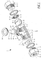
- FIG. 1 shows an exploded view of a fluid valve 1. This consists essentially of a cut illustrated valve housing 2 and a valve body Third
- the valve housing 2 has a through hole 4, in which the spherical valve body 3 is held centrally is. At both end portions 5, this through hole 4 each provided with a thread 6, the recording each of a terminal 7 is used.
- the connection 7 has a threaded shaft 8, which matches the thread 6 of Through hole 4 of the valve housing 2 is formed. In this way, the terminal 7 can be in the valve body 2 set.
- the terminal 7 also has a screw head 9 on, for easy grasping with a fork wrench is shaped hexagonal.
- a central bore 10 is provided, the with an internal thread 11 for receiving a hose connection equipped.
- valve seat 12 is provided by tightening the terminals 7 are pressed against the valve body 3.
- the valve seat 12 consists of a disc, a self-lubricating plastic such as polytetrafluoroethylene.
- a connection 7 facing surface 13 is flat and lies flat frontally the threaded shaft 8.
- An opposite sealing surface 14, however, is formed partially hollow spherical and on the spherical shape of the valve body 3 adapted.
- radial grooves 15 are provided which a Set defined leakage rate of the valve seat 12.
- the valve seat 12 has a central opening 16 on, which can be traversed by the fluid.
- a sealing ring 17 for sealing the terminals 7 relative to the valve housing 2 is also provided a sealing ring 17 in the form of an O-ring, which engages in a shoulder 18 of the valve housing 2.
- the valve body 3 is formed substantially spherical and has a through hole 19, which in the passage position shown in Figure 1 with the Openings 16 of the valve seats 12 comes to cover. In this position is the maximum fluid flow through the Fluid valve 1 guaranteed.
- the valve body 3 has two grooves 20 which are provided at a distance from the through hole 19. These Grooves 20 also provide in a Stellwinkel Anlagen the Valve body 3, in which the through hole 19 is closed is for a low fluid flow through the Fluid valve 1. It is important that between the groove 20 and the through hole 19 still intact Sealing surface 21 remains. Otherwise, the valve body could 3 does not completely close the fluid valve 3.
- a control groove 22 is also provided, in which an actuator 23 of a shaft 24th intervenes. By rotating the shaft 24 can thus be the valve body 3 arbitrarily within the valve housing 2 rotate around the flowing through the fluid valve 1 To adjust fluid quantity.
- this has a bore 25 which is perpendicular to the through hole 4 is aligned.
- the bore 25 is valve inside gradually pulled inside.
- Valve is outside a threaded ring 26 is screwed into the valve housing 2, its inner diameter also smaller than the diameter the bore 25 is.
- In mounted position of the threaded ring 26 results in a hole that in both End areas is tapered.
- In this hole is a disc-shaped portion 27 of the shaft 24 rotatably added.
- another Sealing ring provided for the sake of clarity the illustration is omitted.
- the shaft 24 has Finally, an outside adjustment shaft 28, the Attack of unillustrated levers is used with whose help the valve body 3 can be rotated.
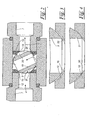
- the function of the fluid valve 1 is based on the sectional view explained in more detail according to FIG.
- the cut takes place along the section line II-II according to FIG 1, so that the fluid valve 1 in the direction of the axis of Shank 24 is considered.
- Location is the valve body 3 so far twisted, that the through hole 4 of the valve body 3 completely is closed.
- the fluid for example from the left port 7 enter and the opening 16 of the valve seat 12 penetrate.
- the fluid then flows through the lower groove 20 in a valve chamber 29, the inside of the valve body 3 and the outside is limited by the valve housing 2.
- the fluid flows around now the valve body 3 and enters in this way in the upper groove 20. From this it passes into the opening 16 of the right valve seat 12 and thus in the right port 7th
- Figure 3 shows an enlarged sectional view of Fluid valve 1 according to Figure 2. From this sectional view is the effect of the grooves 15 to recognize the columns 30 between the valve seat 12 and the valve body. 3 form. In this way it is ensured that also at completely closed valve body 3 a small Fluid quantity substantially without pressure through the fluid valve 1 can flow.
- FIG. 4 shows an alternative embodiment of the fluid valve 1 according to Figure 3, wherein like reference numerals Name the same parts.
- the valve seat 12 is formed such that it faces the valve body 3 forms a gap 30 out.
- This gap 30 is dimensioned to a few hundredths of a millimeter. This is sufficient to a small amount of fluid through the to flow closed fluid valve 1. by virtue of the large flow friction in the small gap 30 becomes the fluid pressure in this gap 30 is practically complete reduced.
Landscapes
- Engineering & Computer Science (AREA)
- General Engineering & Computer Science (AREA)
- Mechanical Engineering (AREA)
- Taps Or Cocks (AREA)
- Multiple-Way Valves (AREA)
- Temperature-Responsive Valves (AREA)
- Lift Valve (AREA)
Abstract
Description
- Figur 1
- eine teilweise geschnittene, räumliche Explosionsdarstellung eines Fluidventils,
- Figur 2
- eine Schnittdarstellung durch das Fluidventil gemäß Figur 1 entlang der Schnittlinie II-II,
- Figur 3
- eine Schnittdarstellung durch das Fluidventil gemäß Figur 1 und
- Figur 4
- eine Schnittdarstellung gemäß Figur 2 einer alternativen Ausführungsform des Fluidventils.
- 1
- Fluidventil
- 2
- Ventilgehäuse
- 3
- Ventilkörper
- 4
- Durchgangsbohrung
- 5
- Endbereich
- 6
- Gewinde
- 7
- Anschluß
- 8
- Gewindeschaft
- 9
- Schraubenkopf
- 10
- Bohrung
- 11
- Innengewinde
- 12
- Ventilsitz
- 13
- Fläche
- 14
- Dichtfläche
- 15
- Rille
- 16
- Öffnung
- 17
- Dichtring
- 18
- Absatz
- 19
- Durchgangsbohrung
- 20
- Nut
- 21
- Dichtungsfläche
- 22
- Stellnut
- 23
- Betätigungsglied
- 24
- Schaft
- 25
- Bohrung
- 26
- Gewindering
- 27
- scheibenförmiger Abschnitt
- 28
- Stellwelle
- 29
- Ventilraum
- 30
- Spalt
Claims (10)
- Fluidventil bestehend aus einem Ventilgehäuse (2) und mindestens einem darin drehbar gelagerten Ventilkörper (3), wobei im Ventilgehäuse (2) mindestens zwei Anschlüsse (7) für ein Fluid vorgesehen sind, welche in einem vorgesehenen Stellwinkelbereich des Ventilkörpers durch eine darin vorgesehene Durchgangsbohrung (4) kommunizieren, dadurch gekennzeichnet, daß der Durchgangsbohrung (4) mindestens eine Nut (20) im Ventilkörper (3) zugeordnet ist, welche in einem erweiterten Stellwinkelbereich eine Verbindung zwischen den Anschlüssen (7) herstellt.
- Fluidventil nach Anspruch 1, dadurch gekennzeichnet, daß die Nuten (20) einen kleineren Querschnitt als Durchgangsbohrung (4) aufweisen.
- Fluidventil nach Anspruch 1 oder 2, dadurch gekennzeichnet, daß sich die Stellwinkelbereiche, in denen die Anschlüsse (7) einerseits über die Durchgangsbohrung (4) und andererseits über die Nuten (20) kommunizieren, überlappen.
- Fluidventil nach mindestens einem der Ansprüche 1 bis 3, dadurch gekennzeichnet, daß die Nuten (20) in etwa parallel zur Durchgangsbohrung (4) und im Abstand zu dieser verlaufen.
- Fluidventil nach mindestens einem der Ansprüche 1 bis 4, dadurch gekennzeichnet, daß die Nuten (20) einander gegenüberliegen.
- Fluidventil nach mindestens einem der Ansprüche 1 bis 5, dadurch gekennzeichnet, daß das Ventilgehäuse (2) Ventilsitze (12) aufweist, an denen der Ventilkörper (3) mit Spalt (30) anliegt, um eine Leckrate des geschlossenen Fluidventils (1) einzustellen.
- Fluidventil nach Anspruch 6, dadurch gekennzeichnet, daß der Ventilsitz (12) radiale Rillen (15) aufweist, die einen Spalt (30) bilden.
- Fluidventil nach Anspruch 6 oder 7, dadurch gekennzeichnet, daß der Ventilsitz (12) von einer Dichtscheibe gebildet ist, die von einer den Anschluß (7) bildenden Schraube (8) gegen den Ventilkörper (3) gedrückt ist.
- Fluidventil nach Anspruch 8, dadurch gekennzeichnet, daß die Schraube (8) mit einer Dichtfläche einen Dichtring (17) gegen das Ventilgehäuse (2) preßt.
- Fluidventil nach mindestens einem der Ansprüche 1 bis 9, dadurch gekennzeichnet, daß die Nut (20) asymmetrisch zur Drehachse des Ventilkörpers (3) vorgesehen ist.
Applications Claiming Priority (2)
| Application Number | Priority Date | Filing Date | Title |
|---|---|---|---|
| DE202004009840U | 2004-06-23 | ||
| DE202004009840U DE202004009840U1 (de) | 2004-06-23 | 2004-06-23 | Fluidventil |
Publications (2)
| Publication Number | Publication Date |
|---|---|
| EP1610043A1 true EP1610043A1 (de) | 2005-12-28 |
| EP1610043B1 EP1610043B1 (de) | 2008-05-28 |
Family
ID=33305410
Family Applications (1)
| Application Number | Title | Priority Date | Filing Date |
|---|---|---|---|
| EP05013585A Expired - Lifetime EP1610043B1 (de) | 2004-06-23 | 2005-06-23 | Fluidventil |
Country Status (3)
| Country | Link |
|---|---|
| EP (1) | EP1610043B1 (de) |
| AT (1) | ATE397176T1 (de) |
| DE (2) | DE202004009840U1 (de) |
Cited By (6)
| Publication number | Priority date | Publication date | Assignee | Title |
|---|---|---|---|---|
| CN102767634A (zh) * | 2012-08-14 | 2012-11-07 | 上海开维喜阀门集团有限公司 | 四通球阀的缺口球体 |
| CN106763860A (zh) * | 2016-12-14 | 2017-05-31 | 石森林 | 球型阀球芯 |
| CN114165624A (zh) * | 2020-09-11 | 2022-03-11 | 浙江三花汽车零部件有限公司 | 阀装置 |
| CN115674992A (zh) * | 2021-07-28 | 2023-02-03 | 浙江三花汽车零部件有限公司 | 流体控制组件以及热管理系统 |
| CN115674991A (zh) * | 2021-07-28 | 2023-02-03 | 浙江三花汽车零部件有限公司 | 热管理系统 |
| CN116761952A (zh) * | 2021-01-28 | 2023-09-15 | 罗伯特·博世有限公司 | 阀 |
Families Citing this family (5)
| Publication number | Priority date | Publication date | Assignee | Title |
|---|---|---|---|---|
| DE102012111468A1 (de) * | 2011-11-30 | 2013-06-06 | Visteon Global Technologies Inc. | Kugelventil mit interner Dichtungsanordnung, insbesondere für den Einsatz in Kraftfahrzeugkältemittelkreisläufen |
| FR3081531B1 (fr) * | 2018-05-24 | 2020-05-29 | Valeo Systemes Thermiques | Vanne 3-voies |
| CN112984141B (zh) * | 2021-03-05 | 2022-12-09 | 新达泵阀股份有限公司 | 一种流量自调液压装置 |
| DE102022205873A1 (de) * | 2021-06-15 | 2022-12-15 | Robert Bosch Gesellschaft mit beschränkter Haftung | Fluidventileinrichtung für ein Fluidventil |
| DE102021206067A1 (de) | 2021-06-15 | 2022-12-15 | Robert Bosch Gesellschaft mit beschränkter Haftung | Expansionsventileinrichtung für ein Expansionsventil |
Citations (7)
| Publication number | Priority date | Publication date | Assignee | Title |
|---|---|---|---|---|
| US3617027A (en) * | 1970-07-01 | 1971-11-02 | Domer Scaramucci | Rocking seat valve |
| DE2240348A1 (de) * | 1972-08-17 | 1974-03-07 | Stile Craft Mfg Inc | Absperrhahn mit einem als kugel ausgebildeten hahnkueken |
| DE2552279A1 (de) | 1975-11-21 | 1977-06-02 | Ley Maschf W | Offene wasserenthaertungsanlage mit durchlaufregulierung |
| US4236691A (en) * | 1978-11-29 | 1980-12-02 | Jamesbury Corporation | Ball valve to relieve cavity pressure |
| US4881718A (en) * | 1987-11-27 | 1989-11-21 | Jamesbury Corporation | Ball control valve |
| US5524863A (en) * | 1994-06-08 | 1996-06-11 | Daniel Industries, Inc. | Quarter turn rotatable flow control valve |
| GB2363184A (en) * | 1999-09-06 | 2001-12-12 | Alan Frederick Rees | Valved radiator tail |
-
2004
- 2004-06-23 DE DE202004009840U patent/DE202004009840U1/de not_active Expired - Lifetime
-
2005
- 2005-06-23 EP EP05013585A patent/EP1610043B1/de not_active Expired - Lifetime
- 2005-06-23 AT AT05013585T patent/ATE397176T1/de active
- 2005-06-23 DE DE502005004247T patent/DE502005004247D1/de not_active Expired - Lifetime
Patent Citations (7)
| Publication number | Priority date | Publication date | Assignee | Title |
|---|---|---|---|---|
| US3617027A (en) * | 1970-07-01 | 1971-11-02 | Domer Scaramucci | Rocking seat valve |
| DE2240348A1 (de) * | 1972-08-17 | 1974-03-07 | Stile Craft Mfg Inc | Absperrhahn mit einem als kugel ausgebildeten hahnkueken |
| DE2552279A1 (de) | 1975-11-21 | 1977-06-02 | Ley Maschf W | Offene wasserenthaertungsanlage mit durchlaufregulierung |
| US4236691A (en) * | 1978-11-29 | 1980-12-02 | Jamesbury Corporation | Ball valve to relieve cavity pressure |
| US4881718A (en) * | 1987-11-27 | 1989-11-21 | Jamesbury Corporation | Ball control valve |
| US5524863A (en) * | 1994-06-08 | 1996-06-11 | Daniel Industries, Inc. | Quarter turn rotatable flow control valve |
| GB2363184A (en) * | 1999-09-06 | 2001-12-12 | Alan Frederick Rees | Valved radiator tail |
Cited By (9)
| Publication number | Priority date | Publication date | Assignee | Title |
|---|---|---|---|---|
| CN102767634A (zh) * | 2012-08-14 | 2012-11-07 | 上海开维喜阀门集团有限公司 | 四通球阀的缺口球体 |
| CN106763860A (zh) * | 2016-12-14 | 2017-05-31 | 石森林 | 球型阀球芯 |
| CN114165624A (zh) * | 2020-09-11 | 2022-03-11 | 浙江三花汽车零部件有限公司 | 阀装置 |
| CN114165624B (zh) * | 2020-09-11 | 2026-02-03 | 浙江三花汽车零部件有限公司 | 阀装置 |
| CN116761952A (zh) * | 2021-01-28 | 2023-09-15 | 罗伯特·博世有限公司 | 阀 |
| CN115674992A (zh) * | 2021-07-28 | 2023-02-03 | 浙江三花汽车零部件有限公司 | 流体控制组件以及热管理系统 |
| CN115674991A (zh) * | 2021-07-28 | 2023-02-03 | 浙江三花汽车零部件有限公司 | 热管理系统 |
| CN115674992B (zh) * | 2021-07-28 | 2026-04-17 | 浙江三花汽车零部件有限公司 | 流体控制组件以及热管理系统 |
| CN115674991B (zh) * | 2021-07-28 | 2026-04-17 | 浙江三花汽车零部件有限公司 | 热管理系统 |
Also Published As
| Publication number | Publication date |
|---|---|
| DE202004009840U1 (de) | 2004-10-14 |
| EP1610043B1 (de) | 2008-05-28 |
| DE502005004247D1 (de) | 2008-07-10 |
| ATE397176T1 (de) | 2008-06-15 |
Similar Documents
| Publication | Publication Date | Title |
|---|---|---|
| EP3008365B1 (de) | Regelhahn | |
| DE4327825C2 (de) | Drosselrückschlagelement | |
| DE69123764T2 (de) | Vorrichtung für endlagedämpfung und geschwindigkeitsregelung der bewegung eines kolbens in einem druckmittelzylinder | |
| EP0122378B1 (de) | Ventil für hydraulische Systeme | |
| EP1610043B1 (de) | Fluidventil | |
| DE102006031985B4 (de) | Fluiddruckzylindervorrichtung mit Drosselventil | |
| DE2446025A1 (de) | Ventilfluegel fuer ein steuerventil | |
| DE3905636A1 (de) | Schieberventil | |
| EP1696162A1 (de) | Ventiloberteil für Armaturen | |
| EP1090240B1 (de) | Druckbegrenzungsventil | |
| DE102008020975A1 (de) | Absperrhahn, insbesondere Kugelhahn | |
| DE2219112A1 (de) | Gashahn | |
| EP1462692B1 (de) | Ventiloberteil für Armaturen | |
| DE102005017618B4 (de) | Ventil, insbesondere zum kontrollierten Abgeben von sich in einem Dampfkessel ansammelnden Salzen und dergleichen | |
| EP2549156B1 (de) | Ventiloberteil für Armaturen | |
| EP3265704B1 (de) | Ventiloberteil für armaturen | |
| DE2237239B2 (de) | Bohrstrangventil | |
| EP0164438B1 (de) | Hydraulikventil | |
| DE3433704C2 (de) | Einschraub-Drosselventil-Bausatz | |
| DE102010023574A1 (de) | Eckventil | |
| DE3636856A1 (de) | Kugelhahn | |
| EP4137722B1 (de) | Ventilkartusche | |
| DE19709736C1 (de) | Absperrventil, insbesondere Kurzhubventil | |
| EP3591271A1 (de) | Ventiloberteil | |
| DE60204386T2 (de) | Vorrichtung zur Durchflussteuerung in einem hydraulischen Verteiler |
Legal Events
| Date | Code | Title | Description |
|---|---|---|---|
| PUAI | Public reference made under article 153(3) epc to a published international application that has entered the european phase |
Free format text: ORIGINAL CODE: 0009012 |
|
| AK | Designated contracting states |
Kind code of ref document: A1 Designated state(s): AT BE BG CH CY CZ DE DK EE ES FI FR GB GR HU IE IS IT LI LT LU MC NL PL PT RO SE SI SK TR |
|
| AX | Request for extension of the european patent |
Extension state: AL BA HR LV MK YU |
|
| 17P | Request for examination filed |
Effective date: 20060330 |
|
| AKX | Designation fees paid |
Designated state(s): AT BE BG CH CY CZ DE DK EE ES FI FR GB GR HU IE IS IT LI LT LU MC NL PL PT RO SE SI SK TR |
|
| GRAP | Despatch of communication of intention to grant a patent |
Free format text: ORIGINAL CODE: EPIDOSNIGR1 |
|
| GRAS | Grant fee paid |
Free format text: ORIGINAL CODE: EPIDOSNIGR3 |
|
| GRAA | (expected) grant |
Free format text: ORIGINAL CODE: 0009210 |
|
| AK | Designated contracting states |
Kind code of ref document: B1 Designated state(s): AT BE BG CH CY CZ DE DK EE ES FI FR GB GR HU IE IS IT LI LT LU MC NL PL PT RO SE SI SK TR |
|
| REG | Reference to a national code |
Ref country code: GB Ref legal event code: FG4D Free format text: NOT ENGLISH |
|
| REG | Reference to a national code |
Ref country code: CH Ref legal event code: EP |
|
| REF | Corresponds to: |
Ref document number: 502005004247 Country of ref document: DE Date of ref document: 20080710 Kind code of ref document: P |
|
| REG | Reference to a national code |
Ref country code: IE Ref legal event code: FG4D Free format text: LANGUAGE OF EP DOCUMENT: GERMAN |
|
| PG25 | Lapsed in a contracting state [announced via postgrant information from national office to epo] |
Ref country code: SI Free format text: LAPSE BECAUSE OF FAILURE TO SUBMIT A TRANSLATION OF THE DESCRIPTION OR TO PAY THE FEE WITHIN THE PRESCRIBED TIME-LIMIT Effective date: 20080528 |
|
| PG25 | Lapsed in a contracting state [announced via postgrant information from national office to epo] |
Ref country code: ES Free format text: LAPSE BECAUSE OF FAILURE TO SUBMIT A TRANSLATION OF THE DESCRIPTION OR TO PAY THE FEE WITHIN THE PRESCRIBED TIME-LIMIT Effective date: 20080908 Ref country code: FI Free format text: LAPSE BECAUSE OF FAILURE TO SUBMIT A TRANSLATION OF THE DESCRIPTION OR TO PAY THE FEE WITHIN THE PRESCRIBED TIME-LIMIT Effective date: 20080528 |
|
| PG25 | Lapsed in a contracting state [announced via postgrant information from national office to epo] |
Ref country code: NL Free format text: LAPSE BECAUSE OF FAILURE TO SUBMIT A TRANSLATION OF THE DESCRIPTION OR TO PAY THE FEE WITHIN THE PRESCRIBED TIME-LIMIT Effective date: 20080528 |
|
| NLV1 | Nl: lapsed or annulled due to failure to fulfill the requirements of art. 29p and 29m of the patents act | ||
| PG25 | Lapsed in a contracting state [announced via postgrant information from national office to epo] |
Ref country code: IS Free format text: LAPSE BECAUSE OF FAILURE TO SUBMIT A TRANSLATION OF THE DESCRIPTION OR TO PAY THE FEE WITHIN THE PRESCRIBED TIME-LIMIT Effective date: 20080928 |
|
| REG | Reference to a national code |
Ref country code: IE Ref legal event code: FD4D |
|
| PG25 | Lapsed in a contracting state [announced via postgrant information from national office to epo] |
Ref country code: PT Free format text: LAPSE BECAUSE OF FAILURE TO SUBMIT A TRANSLATION OF THE DESCRIPTION OR TO PAY THE FEE WITHIN THE PRESCRIBED TIME-LIMIT Effective date: 20081028 Ref country code: DK Free format text: LAPSE BECAUSE OF FAILURE TO SUBMIT A TRANSLATION OF THE DESCRIPTION OR TO PAY THE FEE WITHIN THE PRESCRIBED TIME-LIMIT Effective date: 20080528 Ref country code: CZ Free format text: LAPSE BECAUSE OF FAILURE TO SUBMIT A TRANSLATION OF THE DESCRIPTION OR TO PAY THE FEE WITHIN THE PRESCRIBED TIME-LIMIT Effective date: 20080528 Ref country code: LT Free format text: LAPSE BECAUSE OF FAILURE TO SUBMIT A TRANSLATION OF THE DESCRIPTION OR TO PAY THE FEE WITHIN THE PRESCRIBED TIME-LIMIT Effective date: 20080528 Ref country code: IE Free format text: LAPSE BECAUSE OF FAILURE TO SUBMIT A TRANSLATION OF THE DESCRIPTION OR TO PAY THE FEE WITHIN THE PRESCRIBED TIME-LIMIT Effective date: 20080528 Ref country code: MC Free format text: LAPSE BECAUSE OF NON-PAYMENT OF DUE FEES Effective date: 20080630 Ref country code: SE Free format text: LAPSE BECAUSE OF FAILURE TO SUBMIT A TRANSLATION OF THE DESCRIPTION OR TO PAY THE FEE WITHIN THE PRESCRIBED TIME-LIMIT Effective date: 20080828 |
|
| PG25 | Lapsed in a contracting state [announced via postgrant information from national office to epo] |
Ref country code: RO Free format text: LAPSE BECAUSE OF FAILURE TO SUBMIT A TRANSLATION OF THE DESCRIPTION OR TO PAY THE FEE WITHIN THE PRESCRIBED TIME-LIMIT Effective date: 20080528 Ref country code: SK Free format text: LAPSE BECAUSE OF FAILURE TO SUBMIT A TRANSLATION OF THE DESCRIPTION OR TO PAY THE FEE WITHIN THE PRESCRIBED TIME-LIMIT Effective date: 20080528 |
|
| PLBE | No opposition filed within time limit |
Free format text: ORIGINAL CODE: 0009261 |
|
| STAA | Information on the status of an ep patent application or granted ep patent |
Free format text: STATUS: NO OPPOSITION FILED WITHIN TIME LIMIT |
|
| PG25 | Lapsed in a contracting state [announced via postgrant information from national office to epo] |
Ref country code: EE Free format text: LAPSE BECAUSE OF FAILURE TO SUBMIT A TRANSLATION OF THE DESCRIPTION OR TO PAY THE FEE WITHIN THE PRESCRIBED TIME-LIMIT Effective date: 20080528 Ref country code: BG Free format text: LAPSE BECAUSE OF FAILURE TO SUBMIT A TRANSLATION OF THE DESCRIPTION OR TO PAY THE FEE WITHIN THE PRESCRIBED TIME-LIMIT Effective date: 20080828 |
|
| 26N | No opposition filed |
Effective date: 20090303 |
|
| REG | Reference to a national code |
Ref country code: CH Ref legal event code: PL |
|
| PG25 | Lapsed in a contracting state [announced via postgrant information from national office to epo] |
Ref country code: CH Free format text: LAPSE BECAUSE OF NON-PAYMENT OF DUE FEES Effective date: 20090630 Ref country code: LI Free format text: LAPSE BECAUSE OF NON-PAYMENT OF DUE FEES Effective date: 20090630 |
|
| PG25 | Lapsed in a contracting state [announced via postgrant information from national office to epo] |
Ref country code: PL Free format text: LAPSE BECAUSE OF FAILURE TO SUBMIT A TRANSLATION OF THE DESCRIPTION OR TO PAY THE FEE WITHIN THE PRESCRIBED TIME-LIMIT Effective date: 20080528 |
|
| PG25 | Lapsed in a contracting state [announced via postgrant information from national office to epo] |
Ref country code: LU Free format text: LAPSE BECAUSE OF NON-PAYMENT OF DUE FEES Effective date: 20080623 Ref country code: CY Free format text: LAPSE BECAUSE OF FAILURE TO SUBMIT A TRANSLATION OF THE DESCRIPTION OR TO PAY THE FEE WITHIN THE PRESCRIBED TIME-LIMIT Effective date: 20080528 Ref country code: HU Free format text: LAPSE BECAUSE OF FAILURE TO SUBMIT A TRANSLATION OF THE DESCRIPTION OR TO PAY THE FEE WITHIN THE PRESCRIBED TIME-LIMIT Effective date: 20081129 |
|
| PG25 | Lapsed in a contracting state [announced via postgrant information from national office to epo] |
Ref country code: TR Free format text: LAPSE BECAUSE OF FAILURE TO SUBMIT A TRANSLATION OF THE DESCRIPTION OR TO PAY THE FEE WITHIN THE PRESCRIBED TIME-LIMIT Effective date: 20080528 |
|
| PG25 | Lapsed in a contracting state [announced via postgrant information from national office to epo] |
Ref country code: GR Free format text: LAPSE BECAUSE OF FAILURE TO SUBMIT A TRANSLATION OF THE DESCRIPTION OR TO PAY THE FEE WITHIN THE PRESCRIBED TIME-LIMIT Effective date: 20080829 |
|
| PGFP | Annual fee paid to national office [announced via postgrant information from national office to epo] |
Ref country code: GB Payment date: 20140627 Year of fee payment: 10 |
|
| PGFP | Annual fee paid to national office [announced via postgrant information from national office to epo] |
Ref country code: AT Payment date: 20140626 Year of fee payment: 10 Ref country code: IT Payment date: 20140617 Year of fee payment: 10 |
|
| PGFP | Annual fee paid to national office [announced via postgrant information from national office to epo] |
Ref country code: DE Payment date: 20140821 Year of fee payment: 10 Ref country code: BE Payment date: 20140623 Year of fee payment: 10 |
|
| PGFP | Annual fee paid to national office [announced via postgrant information from national office to epo] |
Ref country code: FR Payment date: 20140623 Year of fee payment: 10 |
|
| REG | Reference to a national code |
Ref country code: DE Ref legal event code: R119 Ref document number: 502005004247 Country of ref document: DE |
|
| PG25 | Lapsed in a contracting state [announced via postgrant information from national office to epo] |
Ref country code: IT Free format text: LAPSE BECAUSE OF NON-PAYMENT OF DUE FEES Effective date: 20150623 |
|
| REG | Reference to a national code |
Ref country code: AT Ref legal event code: MM01 Ref document number: 397176 Country of ref document: AT Kind code of ref document: T Effective date: 20150623 |
|
| GBPC | Gb: european patent ceased through non-payment of renewal fee |
Effective date: 20150623 |
|
| REG | Reference to a national code |
Ref country code: FR Ref legal event code: ST Effective date: 20160229 |
|
| PG25 | Lapsed in a contracting state [announced via postgrant information from national office to epo] |
Ref country code: DE Free format text: LAPSE BECAUSE OF NON-PAYMENT OF DUE FEES Effective date: 20160101 Ref country code: GB Free format text: LAPSE BECAUSE OF NON-PAYMENT OF DUE FEES Effective date: 20150623 |
|
| PG25 | Lapsed in a contracting state [announced via postgrant information from national office to epo] |
Ref country code: FR Free format text: LAPSE BECAUSE OF NON-PAYMENT OF DUE FEES Effective date: 20150630 Ref country code: AT Free format text: LAPSE BECAUSE OF NON-PAYMENT OF DUE FEES Effective date: 20150623 |
|
| PG25 | Lapsed in a contracting state [announced via postgrant information from national office to epo] |
Ref country code: BE Free format text: LAPSE BECAUSE OF NON-PAYMENT OF DUE FEES Effective date: 20150630 |