EP1610047B1 - Ensemble de fond de puits - Google Patents
Ensemble de fond de puits Download PDFInfo
- Publication number
- EP1610047B1 EP1610047B1 EP05253901.2A EP05253901A EP1610047B1 EP 1610047 B1 EP1610047 B1 EP 1610047B1 EP 05253901 A EP05253901 A EP 05253901A EP 1610047 B1 EP1610047 B1 EP 1610047B1
- Authority
- EP
- European Patent Office
- Prior art keywords
- male
- female
- longitudinally
- primary
- tool component
- Prior art date
- Legal status (The legal status is an assumption and is not a legal conclusion. Google has not performed a legal analysis and makes no representation as to the accuracy of the status listed.)
- Expired - Lifetime
Links
Images



Classifications
-
- E—FIXED CONSTRUCTIONS
- E21—EARTH OR ROCK DRILLING; MINING
- E21B—EARTH OR ROCK DRILLING; OBTAINING OIL, GAS, WATER, SOLUBLE OR MELTABLE MATERIALS OR A SLURRY OF MINERALS FROM WELLS
- E21B17/00—Drilling rods or pipes; Flexible drill strings; Kellies; Drill collars; Sucker rods; Cables; Casings; Tubings
- E21B17/02—Couplings; joints
- E21B17/04—Couplings; joints between rod or the like and bit or between rod and rod or the like
- E21B17/042—Threaded
- E21B17/0426—Threaded with a threaded cylindrical portion, e.g. for percussion rods
-
- E—FIXED CONSTRUCTIONS
- E21—EARTH OR ROCK DRILLING; MINING
- E21B—EARTH OR ROCK DRILLING; OBTAINING OIL, GAS, WATER, SOLUBLE OR MELTABLE MATERIALS OR A SLURRY OF MINERALS FROM WELLS
- E21B31/00—Fishing for or freeing objects in boreholes or wells
- E21B31/107—Fishing for or freeing objects in boreholes or wells using impact means for releasing stuck parts, e.g. jars
- E21B31/113—Fishing for or freeing objects in boreholes or wells using impact means for releasing stuck parts, e.g. jars hydraulically-operated
- E21B31/1135—Jars with a hydraulic impedance mechanism, i.e. a restriction, for initially delaying escape of a restraining fluid
-
- F—MECHANICAL ENGINEERING; LIGHTING; HEATING; WEAPONS; BLASTING
- F16—ENGINEERING ELEMENTS AND UNITS; GENERAL MEASURES FOR PRODUCING AND MAINTAINING EFFECTIVE FUNCTIONING OF MACHINES OR INSTALLATIONS; THERMAL INSULATION IN GENERAL
- F16L—PIPES; JOINTS OR FITTINGS FOR PIPES; SUPPORTS FOR PIPES, CABLES OR PROTECTIVE TUBING; MEANS FOR THERMAL INSULATION IN GENERAL
- F16L15/00—Screw-threaded joints; Forms of screw-threads for such joints
- F16L15/006—Screw-threaded joints; Forms of screw-threads for such joints with straight threads
- F16L15/009—Screw-threaded joints; Forms of screw-threads for such joints with straight threads with axial sealings having at least one plastically deformable sealing surface
Definitions
- the present invention relates to connection apparatus and particularly, but not exclusively, to a double shoulder high torque connection used to connect tubular members in a drill string such as tubular members which connect together to form the outer housing of a downhole tool.
- Threaded connection joints such as tapered pin and box joints are used widely in the drilling industry to allow a series of tubulars and components which make up downhole tools and which are connected on the drilling rig to form a drill string for insertion into the borehole.
- Standard connection joints for drill strings typically comprise a tapered male member (pin) on the lower end of one tubular member which may be inserted into a tapered female member (box) on the upper end of another tubular member such that a single shoulder is provided into which a reasonable amount of torque can be applied.
- pin tapered male member
- box tapered female member
- the weakness created in the drill string at the drill pipe and tool component connections has the disadvantage of creating deformation of the joint and/or drill string when a large torsional load is placed upon it.
- a bottom hole assembly tool component according to claim 1.
- the co-operable attachment means of the male and female connecting members retain the primary surface of the male connecting member in abutment with the primary surface of the female connecting member.
- the co-operable attachment means of the male and female connecting members retain the secondary surface of the male connecting member in abutment with the secondary surface of the female connecting member.
- the co-operable attachment means of the male and female connecting members retain the primary and secondary surfaces of the male connecting member in abutment with the respective primary and secondary surfaces of the female connecting member, typically in order to create the respective primary and secondary joints between the male and female members. More preferably, at least one of the primary and secondary joints at least partially resist rotation of one of the connecting members with respect to the other in at least one direction.
- embodiments of the invention provide a pair of butting surfaces (between each pair of primary and secondary surfaces) between the male and female members which resist rotation of the members with respect to one another.
- the primary surface of the female member is located radially outwardly of the secondary surface; the secondary surface of the female member is located closer to the central longitudinal axis of the female connecting member than the primary surface.
- the primary surface of the male member is located radially outwardly of the secondary surface; the secondary surface of the male member is located closer to the central longitudinal axis of the male connecting member than the primary surface.
- the primary surface of the female member comprises a longitudinally outermost end of the female member and may be provided at an end of the female member which is longitudinally and radially outer of the female member attachment means.
- the secondary surface of the female member is distal of the longitudinally outermost end of the female member and may be provided radially and longitudinally inner of the female member attachment means.
- the longitudinally outermost end of the male member may be provided at an end of the male member which is radially inner and longitudinally outer of the male member attachment means.
- the primary surface of the male member is distal of the longitudinally outermost end of the male member and may be provided radially outer and longitudinally inner of the male member attachment means.
- the primary and secondary surfaces of the male and female connecting members further comprise support means which may further comprise a support platform or ledge adapted to support the respective longitudinally outermost ends of the male and female members when the connection means is engaged such that the male member is substantially prevented from moving radially outward and the female member is preferably substantially prevented from moving radially inward.
- the support means is typically provided in the form of a surface, which may be a platform or ledge and which is preferably arranged to lie on an axis substantially parallel or co-axial to the longitudinal axis of the respective male and female connecting members.
- the support means of the primary surface of the male member is arranged radially inwardly of and longitudinally outwardly of the male member primary surface tapered portion and is further arranged radially outwardly of and longitudinally inwardly of the male member attachment means.
- the support means of the secondary surface of the male member is arranged radially outwardly of and longitudinally inwardly of the male member secondary surface tapered portion and is further arranged radially inwardly of and longitudinally outwardly of the male member attachment means.
- the support means of the primary surface of the female member is arranged radially inwardly of and longitudinally inwardly of the female member primary surface tapered portion and is further arranged radially outwardly of and longitudinally outwardly of the female member attachment means.
- the support means of the secondary surface of the female member is arranged radially outwardly of and longitudinally outwardly of the female member secondary surface tapered portion and is further arranged radially inwardly of and longitudinally inwardly of the female member attachment means.
- the combined effect of the support means and tapered surfaces has the advantage that they substantially prevent movement (such as buckling when the connection means is being made up to high levels of torque) of the male and female connection members in the radial direction.
- the male connection member may be provided on one end of a body member and the female member provided on the other thereby creating a double shouldered connection which is capable of remaining engaged when a high torque is applied to it.
- one of a male or female member may be provided on one end of the member only, or in a further alternative, either a male or female member may be provided on each end of the body member.
- the substantially tubular bottom hole assembly tool component members are members which are included in or make up a drill string and may be members provided on or in a drilling jar, impact enhancing tool, drill pipe, flow circulation tool, shock tools, thrusters and bumper subs or other suitable tools.
- connection means in accordance with the present invention will now be described; in this embodiment the connection means is incorporated into a drilling jar.
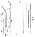
- the connection means comprises an inner or male pin 114 which when connected resides within an outer or female box 116.
- a threaded portion 118 is provided on the outer circumference of the pin 114 and is formed such that it co-operates with a corresponding threaded portion 120 formed on the inner circumference of the box 116.
- the threaded portions 118, 120 typically comprise a V-shaped profile but could, in alternative embodiments, comprise square form, buttress, trapezoidal or acme type threads.
- the threaded portions 118 and 120 are at or near parallel with the longitudinal axis L of the apparatus upon which the connection means is provided and thus are referred to as parallel threads (as opposed to tapered threads commonly used, for instance, in drill pipe connections).
- the pin 114 has a shallow 'v' shaped or gull winged shaped indentation 122, 124 on its longitudinally outermost end face (i.e. the leftmost portion of the pin shown in Fig. 6 ) which comprises a tapered wall 122 and a flat wall 124 as shown in Fig. 6 and which will provide a secondary shoulder surface as will be described subsequently.
- the tapered wall 122 is angled with respect the perpendicular axis to the longitudinal axis L of the male pin 114.
- the tapered wall 122 is angled in the region of 10 to 20 degrees, from radially innermost to outermost, away from the rest of the pin 114 (i.e. the rest of the pin 114 to the right of the flat wall 124) and so is angled, from radially innermost to outermost, away from the parallel thread 118.
- Pin 114 also has a box receiving shoulder 128 which is distal of the tapered wall 122 and which is located radially outer and longitudinally inner of the thread 118, where the shoulder 128 will provide a primary shoulder surface as will be described subsequently.
- the shoulder 128 is angled with respect the perpendicular axis to the longitudinal axis L of the male pin 114 in the region of 10-20 degrees, from radially innermost to outermost, toward the rest of the pin 114 (i.e. the rest of the pin 114 to the left of the shoulder 128) and so is angled, from radially innermost to outermost, toward the parallel thread 118.
- the thread 118 is located radially and longitudinally between the shoulder 128 and the tapered wall 122.
- the outer box 116 has a single tapered face 126 which provides a primary shoulder surface and which is angled with respect to an axis perpendicular to the longitudinal axis L of the outer female box 116.
- the tapered face 126 is angled at approximately 15 degrees, from radially innermost to outermost, toward the rest of the outer female box 116 (i.e. the rest of the box 116 to the left of the tapered face 126) and so is angled, from radially innermost to outermost, toward the parallel thread 120 by substantially the same angle as that of the box receiving shoulder 128.
- the outer box 116 also has tapered pin receiving shoulder 130 which is distal of the tapered face 126 and which is located radially and longitudinally inner of the female thread 120 and which will provide a secondary shoulder surface.
- the pin receiving shoulder 130 is angled in the region of 10-20 degrees, from radially innermost to outermost, away from the rest of the box 116 (i.e. the rest of the box 116 to the right of the pin receiving shoulder 130) and so is angled, from radially innermost to outermost, away from the parallel thread 120.
- the tapered pin receiving shoulder 130 is provided with a substantially similar taper angle as that of tapered wall 122.
- the thread 120 is located radially and longitudinally between the tapered face 126 and the tapered pin receiving shoulder 130.
- box 116 is at least equal to, or preferably slightly longer than the length of inner pin 114 as will be discussed subsequently.
- connection means may be provided on both ends of a double shouldered spline 32.
- Each double shouldered spline 32 comprises a pin 114 and box section 116 which respectively connect to a box and pin section in accordance with the present invention of another component of the apparatus upon which the spline 32 is installed.
- pin 114 is screwed into the box section 116 when the downhole tool is assembled and threads 120 and 118 co-operate to cause tapered face 126 of the box 116 to abut against box receiving shoulder 128 and thereby provides a primary (external of the thread) shoulder junction.
- Tapered wall 122 also abuts against pin receiving shoulder 130 thereby creating a secondary (internal of the thread) metal to metal seal between the tapered face 126 and the shoulder 128 and also providing a secondary shoulder joint between the pin 114 and box 116 into which torque can be delivered and stored; however, as discussed previously, the length of box 116 is manufactured such that it is at least equal to that of pin 114, and is preferably slightly longer (in the order of 0.15 mm) than the length of pin 114. This ensures that the seal created between face 126 and shoulder 128 is made before the seal between wall 122 and shoulder 130 and thus the seal between face 126 and shoulder 128 is regarded as the primary shoulder joint and the internal seal between the wall 122 and shoulder 130 is regarded as the secondary shoulder joint.
- pin 114 When the drill string is compressed when, for example, downward jarring is required (or tensioned when, for example, upward jarring is required) pin 114 is prevented from splaying inwardly toward the longitudinal axis L of the apparatus upon which the connection means is provided due to the abutment between the tapers on wall 122 and shoulder 130.
- the pin 114 is also prevented from diving outwardly (away from the longitudinal axis L) due to a support means in the form of support ledge 140 on the box section 116, where the support ledge 140 is arranged to lie on an axis substantially parallel and co-axial to the longitudinal axis L of the female box section 116.
- the support ledge 140 is arranged radially outwardly of and longitudinally outwardly of the pin receiving shoulder 130 and is therefore located radially inwardly of and longitudinally inwardly of the female thread 120.
- Box section 116 is prevented from splaying outwardly away from the longitudinal axis L of the apparatus due to the taper on wall 126 and shoulder 128.
- the box 116 is also prevented from diving inwardly (toward longitudinal axis L) due to a support ledge 142 on the pin section 114.
- the support ledge 142 is arranged radially inwardly of and longitudinally outwardly of the male shoulder 128 and is therefore located radially outwardly of and longitudinally inwardly of the male thread 118.
- connection means This provides a very secure joint which will withstand very high torsional forces without the pin 114 or box 116 sections splaying or diving inwardly/outwardly since the combined effect of the support ledges 140, 142 and tapered surfaces 122, 130; 126, 128 substantially prevents movement of the male pin 114 and female box 116 in the radial direction.
- the joint created by the connection means also discourages unintentional backing off (i.e.
- connection means unscrewing of the components of the apparatus upon which the connection means is provided since a large rotational force would be required in order to overcome the friction between the primary or external shoulder joint 126; 128 (face 126 and wall 128) and secondary or internal shoulder joint 122; 130 (face 122 and wall 130) once the desired make up torque has been applied to the connection.
- threaded portions 118 and 120 allow a secure connection to be created between two tubulars whilst using a minimal amount of borehole space/radial distance i.e. the joints do not encroach on the internal bore more than absolutely necessary since no taper is required on the threaded portions 118 and 120.
- connection means prevents over stretching of the pin 114 and box 116 sections (which often occurs in standard tapered thread pin and box joints) occurring both during connection of the tubulars and during operation of the drill string. Any tendency for the pin 114 or box 116 to over stretch is avoided by the inability of the pin 114 and box 116 to increase in length due to the respective shoulders 122; 130 and 126; 128.
- connection means permit a much higher level of torque to be applied to itself when screwing the connections together when compared to conventional connections which is particularly useful in extended reach/horizontal wells.
- connection means is not limited to use on the spline 32 and indeed the jar apparatus shown in Figs. 1a, 1b and 1c is provided with further joints J1, J2, J3 and J4 which each have a similarly tapered arrangement and threaded portions which are substantially parallel to the longitudinal axis L of the jar apparatus.
- connection means on the drilling jar of Figs. 1a, 1b and 1c will now be described, though as previously stated the connection means is not limited to use on a drilling jar and indeed it may be used on virtually any tool or tubular where a high torque connection between tubular members may be required e.g. accelerators, drill pipe, flow circulation tools, shock tools, thrusters and bumper subs etc. and any other suitable BHA tools.
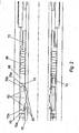
- FIGs. 1A, 1B and 1C show a drilling jar as indicated by the connecting arrows.
- the drilling jar shown in Figs. 1A, 1B and 1C comprises an internal body member or mandrel 10 surrounded by an external body member or housing 12.
- the internal mandrel 10 is arranged such that it may move axially with respect to the external housing 12 when it is required to do so.
- the internal mandrel 10 is a substantially tubular member which spans the majority of the length from the upper to the lower end of the jar apparatus.
- the internal mandrel 10 comprises an uppermost connecting mandrel 14 connected at its lower end to a meter mandrel 16, which leads on to a locking mandrel 18 that finally connects to a lowermost end mandrel 20.
- the external housing 12 comprises an uppermost seal housing 22 connected to an impact housing 23 which leads on to a meter housing 24 connected to a lock housing 26 which connects to a lower seal housing 28 which finally connects to a lowermost connecting housing 30.
- Each of the housings 24, 26 and 28 are connected via connection means in accordance with the present invention and the uppermost seal housing 22 is connected to the impact housing 23 via the double shouldered spline 32 described previously, which is also in accordance with the present invention.
- the uppermost connecting mandrel 14 of the internal mandrel 10 has a box section 34 provided with a standard tapered thread portion 36 which allows connection to a pin section of the lower end of an upper portion of the drill string (not shown).
- the outer circumference of the box section 34 decreases in diameter in order to allow the connecting mandrel 14 to enter the external housing 12.
- box sections are common in the industry and suitable box sections include the HT-50 and XT56 connections provided by Grant Prideco and the WT-58 provided by Hydril.
- the mandrel 14 continues along the internal bore of the housing 12 until it reaches an indented portion 38 which comprises an arrangement of longitudinally extending and circumferentially spaced grooves which telescopically engage with internally projecting splines mounted on the spline 32 to prevent rotation occurring between the internal mandrel 10 and external housing 12.
- a double headed hammer 40 is secured to the outer circumference of the mandrel 14.
- the hammer comprises a collar 40 which has upper 42 and lower 44 impact surfaces and is manufactured such that it may be removed for maintenance or replacement.
- the meter mandrel 16 has a shoulder 46 and a raised diameter portion 50 formed on the mandrel 16 and a locking plate 48 which is attached to the mandrel 16 via a grub screw 52. Situated between the shoulder 46 and the locking plate 48 are upper meter valve 54, lower meter valve 56 and a spacer collar 58. Many suitable meter valves are widely available; however, one-way valves such as the Jeva JetTM provided by The Lee Company, USA are particularly suitable.
- the locking mandrel 18 has circumferentially arranged locking grooves or rings 60 formed on its outer surface which are adapted to selectively coincide with inwardly projecting locking teeth 62 provided on a locking block 64.
- a plurality of, such as six, locking blocks 64 are equi-spaced around the annulus between the internal mandrel 10 and external housing 12 in a cage like structure and are bounded at each upper and lower end by a respective inwardly facing tapered collar 70.
- the teeth 62 are held in the grooves 60 due to an inward force created by the action of compression springs 66 and pre-load spring 68 acting to push the tapered collars 70 toward one another.
- the tapered collars 70 are provided with a highly tapered surface 70a and a shallow tapered surface 70b where the highly tapered surface 70a is radially inner of the shallow tapered surface 70b.
- the force exerted on the locking block 64 by the compression springs 66 can be varied by either screwing in or out an adjuster 72 which increases or decreases (as desired) the inwardly acting force on the locking block 64 due to the action of the tapered collars 70.
- the plurality of locking blocks 64 provided around the circumference of the locking mandrel 18 are each held apart by a circumferential spacer plate (not shown) and rods 73. This prevents the locking blocks 64 from falling to one side of the jar apparatus when e.g. the jar apparatus is placed on its side on the rig for storage, or when the apparatus is used in a highly deviated well.
- the end mandrel 20 (shown in Fig. 1C ) creates a chamber 74 between the end mandrel 20 outer circumference and the external housing 12 internal circumference.
- the end mandrel 20 also provides additional weight to be used in the jarring process.
- the uppermost seal housing 22 of the external housing 12 provides a fluid chamber 75 which is provided with a moveable balance piston 78 and a seal 80.
- a fluid port 76 which is open to the surrounding wellbore is also provided through the wall of the uppermost seal housing 22.
- a plug 82 is provided on the seal housing 22 to obturate another part but which is located below the balance piston 78, such that hydraulic fluid can be inserted into the annulus between the external housing 12 and internal mandrel 10.
- This arrangement prevents any pressure differential from building up across the wall of jar apparatus since any increase in pressure below the piston 78 will be compensated for by the piston 78 moving upwardly and any decrease in pressure below the piston 78 will be compensated for by the piston 78 moving downward.
- This has the advantage of preventing build up of pressure (which may damage or otherwise adversely affect operation of the tool) in the apparatus whilst avoiding hydraulic fluid in the apparatus from mixing with the oil/other material surrounding the apparatus.
- the impact housing 23 is provided with an internal shoulder 84 which is positioned such that it provides an anvil 84 against which the lower impact surface 44 of the hammer 40 may impact.
- a shoulder is provided on the spline 32 to provide an anvil against which the upper impact surface 42 of the hammer 40 may impact.
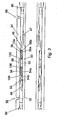
- the meter housing 24 (best shown in Fig. 3 ) has a restricted portion 86 which projects inwardly from the internal circumference of the housing 24.
- the restricted portion 86 is positioned such that it coincides with the spacer collar 58 when the apparatus is in a neutral position i.e. the internal mandrel 10 has not been moved with respect to the external housing 12.
- the chamber created between the meter housing 24 and the meter mandrel 16 is filled with hydraulic fluid which is retained within this chamber due to the presence of plugs (not shown) in ports 88 and end seals 90 provided in the chamber as seen in Fig. 3 .
- the lock housing 26 has a shoulder 92 which provides a point against which the compression spring arrangement 66 may act.
- the lower seal housing 28 provides a fluid chamber 74 which has a moveable balance piston 94 located therein.
- a plug 96 is also provided on the seal housing 22. This arrangement prevents any pressure differential from building up across the wall of apparatus by providing a similar compensation system to that previously described for the upper seal housing 22.
- the lowermost connecting housing 30 has a pin section 98 provided with a standard tapered thread portion 100 which allows connection to a box section of the upper end of a lower portion of the drill string (not shown).
- a series of inwardly protruding shoulders 102, 104, 106, 108 and 110 are created by the connection means provided between each of the components making up the external housing 12 and outwardly projecting shoulders 42 and 112 are also created on the internal mandrel 10 by the connections between each of the components making up the internal mandrel 10.
- the jar apparatus In operation, the jar apparatus is installed in the drill string prior to inserting the drill string downhole. In the event that the drill string becomes stuck downhole due to, for example, the drill bit becoming lodged in the formation being drilled, the jar apparatus can be brought into operation by the operator in order to free the drill bit from the formation.
- the operator may chose to jar the apparatus (and hence the drill string) in the upward or the downward direction, or a combination of both.
- the highly tapered surfaces 70a of the tapered collars 70 result in a relatively large force being required to move the locking block 64 outwardly; however, once the locking block 64 has moved outwardly it is held between shallow tapered surfaces 70b which gently push the locking block 64 inwardly due to the action of the compression springs 66.
- This arrangement has the great advantage that it reduces friction on the locking mandrel 18 since the locking blocks 64 around the circumference of the locking mandrel 18 only grip the locking mandrel 18 lightly as the locking mandrel moves axially along the jar apparatus. With the locking block 64 moved outwardly, the internal mandrel 10 is now able to move with respect to the external housing 12.
- the inner mandrel 10 When the upper impact surface 42 of the double headed hammer 40 reaches the inwardly protruding shoulder 102 the inner mandrel 10 is stopped due to the impact between surface 42 and hammer 40. This causes the momentum of the inner mandrel 10 to be transferred to the outer housing 12.
- the weight provided by the lowermost end mandrel 20 acts to increase the force exerted on the outer housing 12 due to the impact. The transfer of force to the outer housing 12 assists removal of the stuck drill bit from the formation.
- the upper portion of the drill string is pushed downwardly by the operator via the drilling rig (not shown). This exerts a downward force on the internal mandrel 10 with respect to the external housing 12 (which is prevented from moving downwardly due to the stuck drill bit (not shown)).
- the locking block 64 allows movement of the internal mandrel 10 with respect to the external housing 12.
Landscapes
- Engineering & Computer Science (AREA)
- Life Sciences & Earth Sciences (AREA)
- Geology (AREA)
- Mining & Mineral Resources (AREA)
- Physics & Mathematics (AREA)
- Environmental & Geological Engineering (AREA)
- Fluid Mechanics (AREA)
- Mechanical Engineering (AREA)
- General Life Sciences & Earth Sciences (AREA)
- Geochemistry & Mineralogy (AREA)
- General Engineering & Computer Science (AREA)
- Marine Sciences & Fisheries (AREA)
- Earth Drilling (AREA)
- Quick-Acting Or Multi-Walled Pipe Joints (AREA)
- Food-Manufacturing Devices (AREA)
Claims (16)
- Un composant d'outil d'assemblage de fond comprenant un appareil de raccordement conçu pour permettre le raccordement d'un élément de composant d'outil d'assemblage de fond substantiellement tubulaire à un autre élément de composant d'outil d'assemblage de fond substantiellement tubulaire, l'appareil de raccordement comprenant :un élément de raccordement mâle (114) ayant un filetage (118) sur celui-ci ;un élément de raccordement femelle (116) ayant un filetage (120) sur celui-ci ;et un mécanisme de fixation coopérable fourni sur les éléments de raccordement mâle et femelle, lesdits filetages (118, 120) des éléments de raccordement mâle (114) etfemelle (116) étant arrangés pour se visser ensemble afin de former le mécanisme de fixation coopérable ;les éléments de raccordement mâle (114) et femelle (116) comprenant chacun au moins une surface primaire (126, 128) situées au niveau d'une extrémité des filetages respectifs (118, 120) et qui, ensemble, sont conçues pour former un joint d'épaulement de porteur de charge primaire (126, 128) et comprenant en outre chacun au moins une surface secondaire (122, 124, 130) conçues pour former un joint d'épaulement de porteur de charge secondaire (122, 130) ;les filetages respectifs (118, 120) des éléments mâle (114) et femelle (116) étant substantiellement parallèles à l'axe longitudinal de l'appareil et situés entre les surfaces primaire (126, 128) et secondaire (122, 124, 130) respectives ;une portion effilée des surfaces primaires (126, 128) des éléments de raccordement mâle et femelle (114, 116) étant formée à un angle substantiellement similaire par rapport à un axe perpendiculaire à l'axe longitudinal des éléments de raccordement mâle et femelle respectivement, etles portions effilées (126 et 128) des surfaces primaires des éléments mâle et femelle décrivant un angle du plus interne radialement au plus externe en direction des filetages, etune portion d'épaulement de la surface secondaire (122,124, 130) de chacun des éléments mâle et femelle comprenant une portion effilée formée à un angle substantiellement similaire par rapport à un axe perpendiculaire à l'axe longitudinal des éléments de raccordement mâle et femelle respectivement,et la surface secondaire de l'élément mâle a un renfoncement conformé en V peu profond ou conformé en aile en M sur sa face d'extrémité la plus externe longitudinalement comprenant la portion effilée (122) et une paroi plate (124), la portion effilée décrivant un angle aux alentours de 10 à 20 degrés du plus interne radialement au plus externe, à l'écart des filetages parallèles, etla portion effilée de la surface secondaire de l'élément femelle décrivant un angle du plus interne radialement au plus externe à l'écart des filetages parallèles.
- Un composant d'outil selon la revendication 1, dans lequel le mécanisme de fixation coopérable des éléments de raccordement mâle (114) et femelle (116) retient les surfaces primaire (128) et secondaire (122, 124) de l'élément de raccordement mâle (114) en aboutement avec les surfaces primaire (126) et secondaire (122, 124) respectives de l'élément de raccordement femelle (116), fournissant de ce fait les joints primaire (126, 128) et secondaire (122, 124, 130) respectifs entre les éléments mâle (114) et femelle (116).
- Un composant d'outil selon n'importe quelle revendication précédente, dans lequel le mécanisme de fixation coopérable formé par les filetages (118, 120) pousse la ou chaque surface primaire (126, 128) et/ou secondaire (122, 124, 130) des éléments de raccordement (114, 116) en aboutement avec la surface correspondante de l'autre élément de raccordement.
- Un composant d'outil selon n'importe quelle revendication précédente, dans lequel le mécanisme de fixation coopérable a une étendue radiale minimisée de telle sorte que l'alésage interne des éléments de raccordement (114, 116) soit substantiellement non restreint au niveau de l'emplacement des joints d'épaulement.
- Un composant d'outil selon n'importe quelle revendication précédente, dans lequel la surface primaire (126) de l'élément femelle (116) est située radialement vers l'extérieur par rapport à la surface secondaire (130) de telle sorte que la surface secondaire (130) de l'élément femelle (116) soit située plus près de l'axe longitudinal central de l'élément de raccordement femelle (116) que la surface primaire (126).
- Un composant d'outil selon n'importe quelle revendication précédente, dans lequel la surface primaire (128) de l'élément mâle (114) est située radialement vers l'extérieur par rapport à la surface secondaire (122, 124) de telle sorte que la surface secondaire (122, 124) de l'élément mâle (114) soit située plus près de l'axe longitudinal central de l'élément de raccordement mâle (114) que la surface primaire (128).
- Un composant d'outil selon n'importe quelle revendication précédente, dans lequel la surface primaire (126) de l'élément femelle (116) comprend une extrémité la plus externe longitudinalement de l'élément femelle (116) et est fournie au niveau d'une extrémité de l'élément femelle (116) qui est longitudinalement et radialement externe par rapport au filetage d'élément femelle (120), et dans lequel la surface secondaire (130) de l'élément femelle (116) est distale par rapport à l'extrémité la plus externe longitudinalement de l'élément femelle (116) et est fournie de manière radialement et longitudinalement interne par rapport au filetage femelle (120).
- Un composant d'outil selon n'importe quelle revendication précédente, dans lequel l'extrémité la plus externe longitudinalement de l'élément mâle (114) est fournie au niveau d'une extrémité de l'élément mâle (114) qui est radialement interne et longitudinalement externe par rapport au filetage mâle (118), et dans lequel la surface primaire (128) de l'élément mâle (114) est distale de l'extrémité la plus externe longitudinalement de l'élément mâle (114) et est fournie de manière radialement externe et longitudinalement interne du filetage mâle (118).
- Un composant d'outil selon n'importe quelle revendication précédente, dans lequel l'extrémité la plus externe longitudinalement de l'élément femelle (116) se voit substantiellement empêchée de se déplacer radialement vers l'extérieur lorsqu'elle est raccordée à l'élément mâle (114).
- Un composant d'outil selon n'importe quelle revendication précédente, dans lequel l'extrémité la plus externe longitudinalement de l'élément mâle (114) se voit substantiellement empêchée de se déplacer radialement vers l'intérieur lorsqu'elle est raccordée à l'élément femelle (116).
- Un composant d'outil selon n'importe quelle revendication précédente, dans lequel les surfaces primaire (126, 128) et secondaire (122, 124, 130) des éléments de raccordement mâle (114) et femelle (116) comprennent en outre une surface de support (140, 142), la surface de support (140, 142) étant conçue pour supporter les extrémités les plus externes longitudinalement respectives des éléments mâle et femelle (114, 116) lorsque l'appareil de raccordement est mis en prise de telle sorte que l'élément mâle (114) se voie substantiellement empêché de se déplacer radialement vers l'extérieur et que l'élément femelle (116) se voie substantiellement empêché de se déplacer radialement vers l'intérieur.
- Un composant d'outil selon la revendication 11, dans lequel la surface de support (140, 142) est arrangée pour reposer sur un axe substantiellement parallèle ou coaxial à l'axe longitudinal des éléments de raccordement mâle (114) et femelle (116) respectifs.
- Un composant d'outil selon la revendication 12, dans lequel la surface de support (142) de la surface primaire (128) de l'élément mâle (114) est arrangée radialement vers l'intérieur de la portion effilée de surface primaire d'élément mâle (128) et longitudinalement vers l'extérieur de celle-ci et est arrangée en outre radialement vers l'extérieur du filetage mâle (118) et longitudinalement vers l'intérieur de celui-ci, et dans lequel la surface de support de la surface secondaire de l'élément mâle (114) est arrangée radialement vers l'extérieur de la portion effilée de surface secondaire d'élément mâle (122, 124) et longitudinalement vers l'intérieur de celle-ci et est arrangée en outre radialement vers l'intérieur du filetage mâle (118) et longitudinalement vers l'extérieur de celui-ci.
- Un composant d'outil selon l'une ou l'autre des revendications 12 et 13, dans lequel la surface de support de la surface primaire de l'élément femelle (116) est arrangée radialement vers l'intérieur de la portion effilée de surface primaire d'élément femelle (126) et longitudinalement vers l'intérieur de celle-ci et est arrangée en outre radialement vers l'extérieur du filetage femelle (120) et longitudinalement vers l'extérieur de celui-ci, et dans lequel la surface de support (140) de la surface secondaire (130) de l'élément femelle (116) est arrangée radialement vers l'extérieur de la portion effilée de surface secondaire d'élément femelle (130) et longitudinalement vers l'extérieur de celle-ci et est arrangée en outre radialement vers l'intérieur du filetage femelle (120) et longitudinalement vers l'intérieur de celui-ci.
- Un composant d'outil selon n'importe quelle revendication précédente, dans lequel l'élément de raccordement mâle (114) est fourni sur une extrémité d'un élément de corps et l'élément femelle (116) est fourni sur l'autre, créant de ce fait un raccordement à double épaulement qui est capable de rester en prise lorsqu'un couple élevé est appliqué sur celui-ci.
- Un composant d'outil selon n'importe quelle revendication précédente, dans lequel les éléments de composant d'outil d'assemblage de fond substantiellement tubulaires sont des éléments qui sont inclus dans un train de tiges, et dans lequel les éléments tubulaires sont sélectionnés dans le groupe consistant en : une glissière de forage, un outil d'amélioration d'impact, un outil de circulation de flux, un outil de choc, des propulseurs ou des coulisses de battage.
Applications Claiming Priority (2)
| Application Number | Priority Date | Filing Date | Title |
|---|---|---|---|
| GBGB0413998.6A GB0413998D0 (en) | 2004-06-23 | 2004-06-23 | Connection apparatus and method |
| GB0413998 | 2004-06-23 |
Publications (3)
| Publication Number | Publication Date |
|---|---|
| EP1610047A2 EP1610047A2 (fr) | 2005-12-28 |
| EP1610047A3 EP1610047A3 (fr) | 2006-03-22 |
| EP1610047B1 true EP1610047B1 (fr) | 2014-12-17 |
Family
ID=32799979
Family Applications (1)
| Application Number | Title | Priority Date | Filing Date |
|---|---|---|---|
| EP05253901.2A Expired - Lifetime EP1610047B1 (fr) | 2004-06-23 | 2005-06-23 | Ensemble de fond de puits |
Country Status (5)
| Country | Link |
|---|---|
| US (1) | US8052176B2 (fr) |
| EP (1) | EP1610047B1 (fr) |
| CA (1) | CA2510632C (fr) |
| GB (1) | GB0413998D0 (fr) |
| NO (1) | NO334419B1 (fr) |
Families Citing this family (11)
| Publication number | Priority date | Publication date | Assignee | Title |
|---|---|---|---|---|
| GB0413996D0 (en) * | 2004-06-23 | 2004-07-28 | Pedem Ltd | "Impact enhancing apparatus and method" |
| RU2455136C2 (ru) * | 2007-06-06 | 2012-07-10 | Лувата Эспоо Ой | Держатель электрода для контактной сварки |
| US8281868B2 (en) * | 2010-02-05 | 2012-10-09 | Tesco Corporation | Torque transmitting load shoulder |
| CN102787809B (zh) * | 2012-08-23 | 2014-11-19 | 中国石油天然气股份有限公司 | 钻工具接头特殊螺纹 |
| US9551199B2 (en) | 2014-10-09 | 2017-01-24 | Impact Selector International, Llc | Hydraulic impact apparatus and methods |
| US9644441B2 (en) | 2014-10-09 | 2017-05-09 | Impact Selector International, Llc | Hydraulic impact apparatus and methods |
| CN104338974B (zh) * | 2014-10-27 | 2017-10-27 | 株洲钻石切削刀具股份有限公司 | 一种可重复装卸的旋转刀具 |
| US10273761B2 (en) | 2014-12-17 | 2019-04-30 | Halliburton Energy Services, Inc. | Axial retention connection for a downhole tool |
| WO2016112451A1 (fr) | 2015-01-12 | 2016-07-21 | Halliburton Energy Services, Inc. | Raccord pour transmettre des forces de couple et axiales |
| WO2017048247A1 (fr) | 2015-09-16 | 2017-03-23 | Halliburton Energy Services, Inc. | Ensemble de transmission pour moteur de fond de trou |
| US11313194B2 (en) * | 2020-05-20 | 2022-04-26 | Saudi Arabian Oil Company | Retrieving a stuck downhole component |
Family Cites Families (13)
| Publication number | Priority date | Publication date | Assignee | Title |
|---|---|---|---|---|
| DE2438387C3 (de) | 1974-08-07 | 1978-03-09 | Mannesmannroehren-Werke Ag, 4000 Duesseldorf | Gewindeverbindung für Ölfeldrohre |
| US4192533A (en) * | 1976-04-22 | 1980-03-11 | Hydril Company | Dovetail connection for pin and box joints |
| GB2113334B (en) * | 1982-01-18 | 1985-11-13 | Hunting Oilfield Services | Improvements in and relating to pipe connectors |
| US4572549A (en) * | 1982-08-24 | 1986-02-25 | Cameron Iron Works, Inc. | Subsea pipelines |
| CA1233855A (fr) * | 1983-04-05 | 1988-03-08 | Hunting Oilfield Services (International) Limited | Raccords de tuyauterie |
| US4753460A (en) * | 1985-04-26 | 1988-06-28 | The Hydril Company | Tubular connection having two thread sets with multiple interengaging characteristics |
| US4676529A (en) * | 1986-03-24 | 1987-06-30 | Hydril Company | Pipe joint |
| USH1329H (en) * | 1992-04-28 | 1994-07-05 | Exxon Production Research Company | Drill collar connections |
| US5681059A (en) * | 1995-12-15 | 1997-10-28 | Mackie; Michael J. | Pipe connector |
| WO1998054501A1 (fr) * | 1997-05-30 | 1998-12-03 | Sumitomo Metal Industries, Ltd. | Joint a vis pour tuyau de puits de petrole |
| US6305723B1 (en) * | 1998-10-27 | 2001-10-23 | Grant Prideco, L.P. | Tool joint and drill pipe made therefrom |
| US6767035B2 (en) * | 2002-03-11 | 2004-07-27 | Weatherford/Lamb, Inc. | High torque modified profile threaded tubular connection |
| GB0413996D0 (en) * | 2004-06-23 | 2004-07-28 | Pedem Ltd | "Impact enhancing apparatus and method" |
-
2004
- 2004-06-23 GB GBGB0413998.6A patent/GB0413998D0/en not_active Ceased
-
2005
- 2005-06-22 NO NO20053063A patent/NO334419B1/no unknown
- 2005-06-23 EP EP05253901.2A patent/EP1610047B1/fr not_active Expired - Lifetime
- 2005-06-23 CA CA2510632A patent/CA2510632C/fr not_active Expired - Lifetime
- 2005-06-23 US US11/159,395 patent/US8052176B2/en not_active Expired - Lifetime
Also Published As
| Publication number | Publication date |
|---|---|
| CA2510632A1 (fr) | 2005-12-23 |
| US20050287854A1 (en) | 2005-12-29 |
| NO20053063D0 (no) | 2005-06-22 |
| GB0413998D0 (en) | 2004-07-28 |
| EP1610047A2 (fr) | 2005-12-28 |
| CA2510632C (fr) | 2013-06-04 |
| EP1610047A3 (fr) | 2006-03-22 |
| NO334419B1 (no) | 2014-03-03 |
| US8052176B2 (en) | 2011-11-08 |
| NO20053063L (no) | 2005-12-27 |
Similar Documents
| Publication | Publication Date | Title |
|---|---|---|
| US8684096B2 (en) | Anchor assembly and method of installing anchors | |
| US9267338B1 (en) | In-well disconnect tool | |
| CN102333933B (zh) | 具有可移除剪切元件的海上钻井隔水管连接器 | |
| US9512684B2 (en) | Shock tool for drillstring | |
| US9771762B2 (en) | Downhole separation apparatus and method | |
| US11072985B2 (en) | Unlocking and unblocking tool for disconnect assembly for cylindrical members | |
| US20100252252A1 (en) | Hydraulic setting assembly | |
| GB2314391A (en) | High strength quick connector for tools | |
| CA2510632C (fr) | Appareil et methode de raccordement | |
| US20170044843A1 (en) | Downhole swivel sub and method for releasing a stuck object in a wellbore | |
| US20140102804A1 (en) | Agitator sub | |
| US20140060854A1 (en) | Hydraulic Disconnect Apparatus and Method of Use | |
| JP2005511929A (ja) | ダウンホールアセンブリの解放可能な連結 | |
| AU2010366670A1 (en) | Hydraulic/mechanical tight hole jar | |
| EP1609945B1 (fr) | Outil et procédé pour renforcer l'impacts de frappe | |
| US20210404266A1 (en) | System and method for controlling a downhole operation using a clutch tool | |
| US11674361B1 (en) | Method and apparatus for setting downhole plugs and other objects in wellbores | |
| US11434700B2 (en) | Disconnecting a stuck drill pipe | |
| US20230039813A1 (en) | Releasable retrieving tool with lug and slot connection | |
| EP2151615B1 (fr) | Appareil de connexion et procédé | |
| EP2955318A1 (fr) | Raccord à pivot de fond de trou et procédé pour libérer un objet coincé dans un puits de forage | |
| US11035179B2 (en) | Disconnecting a stuck drill pipe | |
| EP4085178B1 (fr) | Coulisse hydraulique à verrouillage mécanique et procédé associé | |
| US20120306196A1 (en) | Anti-back off device for down hole tools and drive systems |
Legal Events
| Date | Code | Title | Description |
|---|---|---|---|
| PUAI | Public reference made under article 153(3) epc to a published international application that has entered the european phase |
Free format text: ORIGINAL CODE: 0009012 |
|
| AK | Designated contracting states |
Kind code of ref document: A2 Designated state(s): AT BE BG CH CY CZ DE DK EE ES FI FR GB GR HU IE IS IT LI LT LU MC NL PL PT RO SE SI SK TR |
|
| AX | Request for extension of the european patent |
Extension state: AL BA HR LV MK YU |
|
| PUAL | Search report despatched |
Free format text: ORIGINAL CODE: 0009013 |
|
| AK | Designated contracting states |
Kind code of ref document: A3 Designated state(s): AT BE BG CH CY CZ DE DK EE ES FI FR GB GR HU IE IS IT LI LT LU MC NL PL PT RO SE SI SK TR |
|
| AX | Request for extension of the european patent |
Extension state: AL BA HR LV MK YU |
|
| 17P | Request for examination filed |
Effective date: 20060904 |
|
| AKX | Designation fees paid |
Designated state(s): AT BE BG CH CY CZ DE DK EE ES FI FR GB GR HU IE IS IT LI LT LU MC NL PL PT RO SE SI SK TR |
|
| 17Q | First examination report despatched |
Effective date: 20061130 |
|
| RAP1 | Party data changed (applicant data changed or rights of an application transferred) |
Owner name: PEDEM LIMITED |
|
| REG | Reference to a national code |
Ref country code: DE Ref legal event code: R079 Ref document number: 602005045445 Country of ref document: DE Free format text: PREVIOUS MAIN CLASS: F16L0015000000 Ipc: E21B0031113000 |
|
| RIC1 | Information provided on ipc code assigned before grant |
Ipc: E21B 17/042 20060101ALI20131011BHEP Ipc: E21B 31/113 20060101AFI20131011BHEP Ipc: F16L 15/00 20060101ALI20131011BHEP |
|
| GRAP | Despatch of communication of intention to grant a patent |
Free format text: ORIGINAL CODE: EPIDOSNIGR1 |
|
| INTG | Intention to grant announced |
Effective date: 20140219 |
|
| GRAP | Despatch of communication of intention to grant a patent |
Free format text: ORIGINAL CODE: EPIDOSNIGR1 |
|
| INTG | Intention to grant announced |
Effective date: 20140708 |
|
| GRAS | Grant fee paid |
Free format text: ORIGINAL CODE: EPIDOSNIGR3 |
|
| GRAA | (expected) grant |
Free format text: ORIGINAL CODE: 0009210 |
|
| AK | Designated contracting states |
Kind code of ref document: B1 Designated state(s): AT BE BG CH CY CZ DE DK EE ES FI FR GB GR HU IE IS IT LI LT LU MC NL PL PT RO SE SI SK TR |
|
| REG | Reference to a national code |
Ref country code: GB Ref legal event code: FG4D |
|
| REG | Reference to a national code |
Ref country code: DE Ref legal event code: R081 Ref document number: 602005045445 Country of ref document: DE Owner name: ANCO APS, DK Free format text: FORMER OWNER: PEDEM LTD., BRIDGE OF DONABERDEEN, GB |
|
| REG | Reference to a national code |
Ref country code: CH Ref legal event code: EP |
|
| REG | Reference to a national code |
Ref country code: IE Ref legal event code: FG4D |
|
| REG | Reference to a national code |
Ref country code: AT Ref legal event code: REF Ref document number: 702085 Country of ref document: AT Kind code of ref document: T Effective date: 20150115 |
|
| REG | Reference to a national code |
Ref country code: DE Ref legal event code: R096 Ref document number: 602005045445 Country of ref document: DE Effective date: 20150205 |
|
| REG | Reference to a national code |
Ref country code: NL Ref legal event code: T3 |
|
| PG25 | Lapsed in a contracting state [announced via postgrant information from national office to epo] |
Ref country code: LT Free format text: LAPSE BECAUSE OF FAILURE TO SUBMIT A TRANSLATION OF THE DESCRIPTION OR TO PAY THE FEE WITHIN THE PRESCRIBED TIME-LIMIT Effective date: 20141217 Ref country code: FI Free format text: LAPSE BECAUSE OF FAILURE TO SUBMIT A TRANSLATION OF THE DESCRIPTION OR TO PAY THE FEE WITHIN THE PRESCRIBED TIME-LIMIT Effective date: 20141217 |
|
| REG | Reference to a national code |
Ref country code: LT Ref legal event code: MG4D |
|
| PG25 | Lapsed in a contracting state [announced via postgrant information from national office to epo] |
Ref country code: SE Free format text: LAPSE BECAUSE OF FAILURE TO SUBMIT A TRANSLATION OF THE DESCRIPTION OR TO PAY THE FEE WITHIN THE PRESCRIBED TIME-LIMIT Effective date: 20141217 Ref country code: GR Free format text: LAPSE BECAUSE OF FAILURE TO SUBMIT A TRANSLATION OF THE DESCRIPTION OR TO PAY THE FEE WITHIN THE PRESCRIBED TIME-LIMIT Effective date: 20150318 |
|
| REG | Reference to a national code |
Ref country code: AT Ref legal event code: MK05 Ref document number: 702085 Country of ref document: AT Kind code of ref document: T Effective date: 20141217 |
|
| PG25 | Lapsed in a contracting state [announced via postgrant information from national office to epo] |
Ref country code: SK Free format text: LAPSE BECAUSE OF FAILURE TO SUBMIT A TRANSLATION OF THE DESCRIPTION OR TO PAY THE FEE WITHIN THE PRESCRIBED TIME-LIMIT Effective date: 20141217 Ref country code: CZ Free format text: LAPSE BECAUSE OF FAILURE TO SUBMIT A TRANSLATION OF THE DESCRIPTION OR TO PAY THE FEE WITHIN THE PRESCRIBED TIME-LIMIT Effective date: 20141217 Ref country code: ES Free format text: LAPSE BECAUSE OF FAILURE TO SUBMIT A TRANSLATION OF THE DESCRIPTION OR TO PAY THE FEE WITHIN THE PRESCRIBED TIME-LIMIT Effective date: 20141217 Ref country code: EE Free format text: LAPSE BECAUSE OF FAILURE TO SUBMIT A TRANSLATION OF THE DESCRIPTION OR TO PAY THE FEE WITHIN THE PRESCRIBED TIME-LIMIT Effective date: 20141217 Ref country code: PT Free format text: LAPSE BECAUSE OF FAILURE TO SUBMIT A TRANSLATION OF THE DESCRIPTION OR TO PAY THE FEE WITHIN THE PRESCRIBED TIME-LIMIT Effective date: 20150417 Ref country code: RO Free format text: LAPSE BECAUSE OF FAILURE TO SUBMIT A TRANSLATION OF THE DESCRIPTION OR TO PAY THE FEE WITHIN THE PRESCRIBED TIME-LIMIT Effective date: 20141217 |
|
| PG25 | Lapsed in a contracting state [announced via postgrant information from national office to epo] |
Ref country code: PL Free format text: LAPSE BECAUSE OF FAILURE TO SUBMIT A TRANSLATION OF THE DESCRIPTION OR TO PAY THE FEE WITHIN THE PRESCRIBED TIME-LIMIT Effective date: 20141217 Ref country code: IS Free format text: LAPSE BECAUSE OF FAILURE TO SUBMIT A TRANSLATION OF THE DESCRIPTION OR TO PAY THE FEE WITHIN THE PRESCRIBED TIME-LIMIT Effective date: 20150417 Ref country code: AT Free format text: LAPSE BECAUSE OF FAILURE TO SUBMIT A TRANSLATION OF THE DESCRIPTION OR TO PAY THE FEE WITHIN THE PRESCRIBED TIME-LIMIT Effective date: 20141217 |
|
| REG | Reference to a national code |
Ref country code: DE Ref legal event code: R097 Ref document number: 602005045445 Country of ref document: DE |
|
| PLBE | No opposition filed within time limit |
Free format text: ORIGINAL CODE: 0009261 |
|
| STAA | Information on the status of an ep patent application or granted ep patent |
Free format text: STATUS: NO OPPOSITION FILED WITHIN TIME LIMIT |
|
| PG25 | Lapsed in a contracting state [announced via postgrant information from national office to epo] |
Ref country code: DK Free format text: LAPSE BECAUSE OF FAILURE TO SUBMIT A TRANSLATION OF THE DESCRIPTION OR TO PAY THE FEE WITHIN THE PRESCRIBED TIME-LIMIT Effective date: 20141217 |
|
| 26N | No opposition filed |
Effective date: 20150918 |
|
| PG25 | Lapsed in a contracting state [announced via postgrant information from national office to epo] |
Ref country code: IT Free format text: LAPSE BECAUSE OF FAILURE TO SUBMIT A TRANSLATION OF THE DESCRIPTION OR TO PAY THE FEE WITHIN THE PRESCRIBED TIME-LIMIT Effective date: 20141217 |
|
| PG25 | Lapsed in a contracting state [announced via postgrant information from national office to epo] |
Ref country code: MC Free format text: LAPSE BECAUSE OF FAILURE TO SUBMIT A TRANSLATION OF THE DESCRIPTION OR TO PAY THE FEE WITHIN THE PRESCRIBED TIME-LIMIT Effective date: 20141217 |
|
| REG | Reference to a national code |
Ref country code: CH Ref legal event code: PL |
|
| PG25 | Lapsed in a contracting state [announced via postgrant information from national office to epo] |
Ref country code: LU Free format text: LAPSE BECAUSE OF FAILURE TO SUBMIT A TRANSLATION OF THE DESCRIPTION OR TO PAY THE FEE WITHIN THE PRESCRIBED TIME-LIMIT Effective date: 20150623 Ref country code: SI Free format text: LAPSE BECAUSE OF FAILURE TO SUBMIT A TRANSLATION OF THE DESCRIPTION OR TO PAY THE FEE WITHIN THE PRESCRIBED TIME-LIMIT Effective date: 20141217 |
|
| REG | Reference to a national code |
Ref country code: IE Ref legal event code: MM4A |
|
| PG25 | Lapsed in a contracting state [announced via postgrant information from national office to epo] |
Ref country code: IE Free format text: LAPSE BECAUSE OF NON-PAYMENT OF DUE FEES Effective date: 20150623 Ref country code: CH Free format text: LAPSE BECAUSE OF NON-PAYMENT OF DUE FEES Effective date: 20150630 Ref country code: LI Free format text: LAPSE BECAUSE OF NON-PAYMENT OF DUE FEES Effective date: 20150630 |
|
| PG25 | Lapsed in a contracting state [announced via postgrant information from national office to epo] |
Ref country code: BE Free format text: LAPSE BECAUSE OF FAILURE TO SUBMIT A TRANSLATION OF THE DESCRIPTION OR TO PAY THE FEE WITHIN THE PRESCRIBED TIME-LIMIT Effective date: 20141217 |
|
| REG | Reference to a national code |
Ref country code: FR Ref legal event code: PLFP Year of fee payment: 12 |
|
| REG | Reference to a national code |
Ref country code: DE Ref legal event code: R081 Ref document number: 602005045445 Country of ref document: DE Owner name: ANCO APS, DK Free format text: FORMER OWNER: PEDEM LTD., ESTATE PORTLETHEN, ABERDEENSHIRE, GB Ref country code: DE Ref legal event code: R082 Ref document number: 602005045445 Country of ref document: DE Representative=s name: MURGITROYD & COMPANY, DE |
|
| REG | Reference to a national code |
Ref country code: NL Ref legal event code: PD Owner name: ANCO APS; DK Free format text: DETAILS ASSIGNMENT: CHANGE OF OWNER(S), ASSIGNMENT; FORMER OWNER NAME: PEDEM LIMITED Effective date: 20161221 |
|
| REG | Reference to a national code |
Ref country code: FR Ref legal event code: TP Owner name: ANCO APS, DK Effective date: 20161214 |
|
| PG25 | Lapsed in a contracting state [announced via postgrant information from national office to epo] |
Ref country code: HU Free format text: LAPSE BECAUSE OF FAILURE TO SUBMIT A TRANSLATION OF THE DESCRIPTION OR TO PAY THE FEE WITHIN THE PRESCRIBED TIME-LIMIT; INVALID AB INITIO Effective date: 20050623 Ref country code: BG Free format text: LAPSE BECAUSE OF FAILURE TO SUBMIT A TRANSLATION OF THE DESCRIPTION OR TO PAY THE FEE WITHIN THE PRESCRIBED TIME-LIMIT Effective date: 20141217 |
|
| REG | Reference to a national code |
Ref country code: FR Ref legal event code: PLFP Year of fee payment: 13 |
|
| PG25 | Lapsed in a contracting state [announced via postgrant information from national office to epo] |
Ref country code: CY Free format text: LAPSE BECAUSE OF FAILURE TO SUBMIT A TRANSLATION OF THE DESCRIPTION OR TO PAY THE FEE WITHIN THE PRESCRIBED TIME-LIMIT Effective date: 20141217 |
|
| PG25 | Lapsed in a contracting state [announced via postgrant information from national office to epo] |
Ref country code: TR Free format text: LAPSE BECAUSE OF FAILURE TO SUBMIT A TRANSLATION OF THE DESCRIPTION OR TO PAY THE FEE WITHIN THE PRESCRIBED TIME-LIMIT Effective date: 20141217 |
|
| REG | Reference to a national code |
Ref country code: FR Ref legal event code: PLFP Year of fee payment: 14 |
|
| PGFP | Annual fee paid to national office [announced via postgrant information from national office to epo] |
Ref country code: FR Payment date: 20220627 Year of fee payment: 18 |
|
| PGFP | Annual fee paid to national office [announced via postgrant information from national office to epo] |
Ref country code: DE Payment date: 20220629 Year of fee payment: 18 |
|
| REG | Reference to a national code |
Ref country code: NL Ref legal event code: PD Owner name: EMQ LTD; GB Free format text: DETAILS ASSIGNMENT: CHANGE OF OWNER(S), ASSIGNMENT; FORMER OWNER NAME: PEDEM LIMITED Effective date: 20230414 |
|
| REG | Reference to a national code |
Ref country code: DE Ref legal event code: R119 Ref document number: 602005045445 Country of ref document: DE |
|
| PG25 | Lapsed in a contracting state [announced via postgrant information from national office to epo] |
Ref country code: DE Free format text: LAPSE BECAUSE OF NON-PAYMENT OF DUE FEES Effective date: 20240103 |
|
| PG25 | Lapsed in a contracting state [announced via postgrant information from national office to epo] |
Ref country code: FR Free format text: LAPSE BECAUSE OF NON-PAYMENT OF DUE FEES Effective date: 20230630 |
|
| PGFP | Annual fee paid to national office [announced via postgrant information from national office to epo] |
Ref country code: GB Payment date: 20240628 Year of fee payment: 20 |
|
| PGFP | Annual fee paid to national office [announced via postgrant information from national office to epo] |
Ref country code: NL Payment date: 20240621 Year of fee payment: 20 |
|
| REG | Reference to a national code |
Ref country code: NL Ref legal event code: MK Effective date: 20250622 |
|
| PG25 | Lapsed in a contracting state [announced via postgrant information from national office to epo] |
Ref country code: GB Free format text: LAPSE BECAUSE OF EXPIRATION OF PROTECTION Effective date: 20250622 |
|
| REG | Reference to a national code |
Ref country code: GB Ref legal event code: PE20 Expiry date: 20250622 |