EP1610087B1 - Tastsonde - Google Patents
Tastsonde Download PDFInfo
- Publication number
- EP1610087B1 EP1610087B1 EP04102867A EP04102867A EP1610087B1 EP 1610087 B1 EP1610087 B1 EP 1610087B1 EP 04102867 A EP04102867 A EP 04102867A EP 04102867 A EP04102867 A EP 04102867A EP 1610087 B1 EP1610087 B1 EP 1610087B1
- Authority
- EP
- European Patent Office
- Prior art keywords
- pins
- positioning elements
- spheres
- probe according
- fixed
- Prior art date
- Legal status (The legal status is an assumption and is not a legal conclusion. Google has not performed a legal analysis and makes no representation as to the accuracy of the status listed.)
- Expired - Lifetime
Links
- 239000000523 sample Substances 0.000 title claims description 51
- 230000035945 sensitivity Effects 0.000 claims description 12
- 230000000284 resting effect Effects 0.000 claims description 10
- 210000000056 organ Anatomy 0.000 claims 6
- 239000004020 conductor Substances 0.000 claims 1
- 238000005259 measurement Methods 0.000 description 5
- 238000004519 manufacturing process Methods 0.000 description 4
- 238000001514 detection method Methods 0.000 description 3
- 238000010586 diagram Methods 0.000 description 2
- 239000000853 adhesive Substances 0.000 description 1
- 230000001070 adhesive effect Effects 0.000 description 1
- 230000001010 compromised effect Effects 0.000 description 1
- 230000008021 deposition Effects 0.000 description 1
- 230000001627 detrimental effect Effects 0.000 description 1
- 230000001939 inductive effect Effects 0.000 description 1
- 238000002955 isolation Methods 0.000 description 1
- 239000002184 metal Substances 0.000 description 1
- 238000000034 method Methods 0.000 description 1
- 230000003287 optical effect Effects 0.000 description 1
- 239000003973 paint Substances 0.000 description 1
- 238000003908 quality control method Methods 0.000 description 1
- 239000010979 ruby Substances 0.000 description 1
- 229910001750 ruby Inorganic materials 0.000 description 1
- 239000004575 stone Substances 0.000 description 1
- 238000012795 verification Methods 0.000 description 1
Images


Classifications
-
- G—PHYSICS
- G01—MEASURING; TESTING
- G01B—MEASURING LENGTH, THICKNESS OR SIMILAR LINEAR DIMENSIONS; MEASURING ANGLES; MEASURING AREAS; MEASURING IRREGULARITIES OF SURFACES OR CONTOURS
- G01B5/00—Measuring arrangements characterised by the use of mechanical techniques
- G01B5/004—Measuring arrangements characterised by the use of mechanical techniques for measuring coordinates of points
- G01B5/008—Measuring arrangements characterised by the use of mechanical techniques for measuring coordinates of points using coordinate measuring machines
- G01B5/012—Contact-making feeler heads therefor
Definitions
- the present invention relates to the field of probes for measuring coordinates, and in particular, to a trigger probe based on the principle of the Boys connection suitable for use as an accessory of a machine for measuring coordinates in three dimensions.
- Trigger probes are electromechanical measuring elements widely, but not exclusively, used on production lines for mechanical parts, for example for adjusting production machinery or for quality control. They are used for the precise verification of dimensions, or the control of the regularity of a surface or a batch of production.
- Trigger probes are usually attached to the movable arm of a measuring machine whose position is determined accurately using measuring systems such as capacitive, inductive, magnetoresistive or optical.
- the arm of the measuring machine is moved in space along a determined path until the touch probe touches the workpiece or the surface to be measured.
- a deflection force is applied to the key, thereby removing it from its initial rest position.
- An electrical circuit is then either closed or open and a signal is generally sent on the one hand to the user, for example in the form of a light signal, and on the other hand to the software of the measuring machine which thus determines, for example measurement system data, the coordinates of the point of contact in a given repository.
- the software calculates the distance between two measurement points and, in some cases, represents an object to be measured in two or three dimensions using a series of measurement points.
- the trigger probes are used to control the regularity of a surface or a batch of production.
- a probe is fixed on a stationary element and a surface or a series of pieces scrolls in front of the probe so as to touch the key. If the surface has irregularities or if the parts are not of regular size, the touch probe will be subjected to a force that will remove it from its rest position, thus modifying the signal emitted by the electric circuit of the probe.
- the main elements of a trigger probe are usually a fixed member, a key and an electrical circuit for detecting the movements of the key relative to its rest position.
- the fixed member is fixed relative to the fixing element, the fixing element being generally incorporated in the probe housing and for fixing the probe, for example on the movable arm of a measuring machine.
- the key is the mechanical element intended to come into contact with the surface or the part to be measured.
- the key generally comprises a sphere of contact calibrated in ruby or hard stone fixed to the end of a straight or bent rod which is held by an elastic member in a rest position relative to the fixed member. This rest position is determined and reproducible.
- the key has one or more degrees of freedom with respect to the fixed member. During contact with the surface to be measured, a deflection force is exerted on the key that leaves its rest position according to one or more of its degrees of freedom relative to the fixed member. When the force is no longer applied to the key, the key returns to its rest position.
- the trigger probes comprise an isostatic connection between the key and the fixed member.
- This link has six independent contact points, so as to determine exactly the relative position of the key relative to the fixed member.
- the six points of contact are made by three hard metal pins, oriented at 120 ° to each other, each pin resting between two spheres integral with the fixed member of the probe.
- the spheres are electrically connected to form a circuit having six switches in series to signal contact of the key with the workpiece to be measured.
- the sensitivity of this type of probe to the lateral forces is not uniform, but has three lobes in correspondence of the directions of the three pins. This variation of the sensitivity is detrimental to the repeatability of the trigger and therefore to the quality of the measurement.
- EP0764827 describes a feeler in which a rest position is defined by six balls attached to the ends of the arms of a six-pointed star.
- DE3713415 , DE20006504 and DE4341192 relate to trigger probes in which the rest position of the key is defined by a number of contact points greater than six.
- W09522739 discloses a trigger probe in which the support of the key comprises two rings of balls engaging one another, and also in contact with an annular surface, determining three points of contact per ball. This probe has no electrical circuit passing through the balls, but uses a separate switch.
- An object of the present invention is to provide a trigger probe without disadvantages of the prior art.
- Another object of the present invention is to provide a probe with simple and reliable tripping and having a constant sensitivity to the lateral forces.
- the present invention derives from the observation that the sensitivity of the trigger to the lateral forces can be standardized by judiciously choosing the location of the points of contact. In particular it is possible to distribute the contact points in a hexagonal symmetry arrangement, rotations of 60 °. On the other hand, the distribution of the contact points in the known triggers is symmetrical by rotations of 120 °. In such an arrangement the sensitivity of the probe to the lateral forces is practically constant.
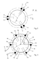
- the figures 1 and 2 represent a trigger probe of known type.
- a probe tip 12 comprises at one end a sphere 15 whose diameter is determined exactly and intended to contact the piece to be measured.
- the probe rod is integral with the plate 13, held in position by the pins 31, 32, 33, resting on the spheres 41-46 under the action of the spring 21.
- the rest position of the key is exactly and reproducibly determined by the six points of contact between the pins 31-33 and the spheres 41-46, according to the principle of the Boys connection.
- the sphere 15 is moved from its rest position, at least one of the six points of contact is interrupted, and the resistance variation of the electrical circuit that follows allows the detection of the contact.
- the vertical component of the force exerted by the plate 13 on the spring 21 must exceed the tension of the latter. It is easily understood that, in the case of a lateral force, this detection threshold is not constant, but depends on the orientation of the force. The force required for detection will be greater for a contact in the d2 direction of the figure 2 only for the direction d1.
- the axis of tilting of the key is at a distance r from the center and, in the case of a deflection force oriented in the direction d1, the tilting takes place at a distance b.
- the sensitivity of this type of probe to the lateral forces is not uniform, but has three lobes in correspondence of the directions of the three pins.
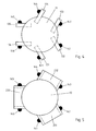
- the figure 3 represents the trigger of a probe according to a first embodiment of the invention.
- the key 12 ends with a plate 13 on the periphery of which are disposed six radial pins 131-136. In the rest position each pin touches a sphere 141-146 secured to the fixed member of the probe.
- Conductive members 90 connect the pins and spheres to provide a normally closed electrical circuit that opens as soon as any of the detach pins of the corresponding sphere.
- pairs of pins 131-132, 133-134 and 135-136, and spheres 142-143 and 144-145 could be connected as shown. schematically on the figure 3 .
- the contact with the part to be measured is detected by the variation of the resistance at the terminals 91, 92 connected to the spheres 141 and 146.
- other arrangements are possible.
- the conductive elements 90 may be made by soldered or glued electric wires, or by deposition of a layer of paint or conductive adhesive, or by any other known method.
- the isolation of the spheres and pins of their relative supports can be obtained for example by eloxing.
- the contact points are arranged along a circumference 80 centered around the axis of the key 12.
- the angular difference ⁇ between each pair of successive contact points is essentially equal to 60 °, so that the points are on the vertexes of a hex centered around the axis of the key.
- the tilt distance of the key 12 is always equal to a for all lateral forces. Naturally the friction forces prevent to reach exactly this ideal ratio.
- the angular difference between each pair of adjacent contact points is preferably exactly equal to 60 ° or in any case is close to this value, for example between 40 ° and 80 °, preferably between 50 ° and 70 °.
- the spheres 141-146 are arranged with respect to the pins 131-136, so that the three spheres 142 144 and 146 precede the pins 132, 134 and respectively 136 when the circumference 80 is scanned clockwise, and the spheres 141, 143 and 145 follow the pins 131, 133 and 135 in the same path.
- This alternate arrangement allows to define a stable and precise rest position.
- Other arrangements in which a portion of spheres 141-146 precedes the pins 131-136 and another part of the spheres 141-146 follows the pins 131-136 are however possible within the scope of the present invention.
- the pins and spheres can be replaced by other positioning elements able to define six point contacts between the fixed member 1 and the plate 12 of the key 13.
- the pins could be replaced by inclined planes.
- the pins 131-136 of the probe of the figure 3 are arranged substantially radially with respect to the axis of the key 12.
- the pins 131-136 are arranged in parallel pairs, in three directions, substantially angularly spaced 120 ° between them.
- the plate 13 carries at its periphery three studs 231, 232, 233, arranged essentially at 120 ° and each stud touches two of the spheres 141-146 of the fixed member.
- the six points of contact between the studs 231-233 and the spheres 141-146 are distributed around the axis of the key 12 so as to obtain a uniform sensitivity to the lateral forces.
- the contact points are placed on the vertexes of a hexagon centered with respect to the axis of the key 12.
- the pins 131-136 are arranged in three pairs of pins converging towards the outside of the plate 13, in a substantially symmetrical arrangement by rotation of 120 °.
- the six points of contact between the pins 131-136 and the spheres 141-146 are distributed around the axis of the key 12 so as to obtain a uniform sensitivity to the lateral forces. They are preferably placed on the vertexes of a hexagon centered with respect to the axis of the key 12.
- the variants of execution represented figures 3 , 4 , 6 are differentiated by a rotation of the pins 131-136 around the respective contact points with the balls 141-146. These examples should not be interpreted in the sense that the invention is limited to these specific angles of orientation of the pins relative to the balls.
- the present invention also includes many other arrangements, characterized by any angle between the pins 131-136 and the balls 141-146.
Landscapes
- Physics & Mathematics (AREA)
- General Physics & Mathematics (AREA)
- Length Measuring Devices With Unspecified Measuring Means (AREA)
- A Measuring Device Byusing Mechanical Method (AREA)
- Measurement Of Length, Angles, Or The Like Using Electric Or Magnetic Means (AREA)
Claims (13)
- Messkopf enthaltend:ein festes Teil (1);einen Messfühler (12), der durch ein elastisches Element (21) in einer Ruheposition relativ zu besagtem festem Teil gehalten wird, besagte Ruheposition ist wieder herstellbar, besagter Messfühler (12) ist fähig, sich aus der Ruheposition als Antwort auf eine ablenkende Kraft zu bewegen, und ist fähig, zu besagter Ruheposition zurückzukehren, wenn besagte Kraft aufhört, angewandt zu werden,eine Vielzahl von beweglichen Positionselementen (131, 132, 133, 134, 135, 136, 231, 232, 233), die mit dem Messfühler (12) verein sind,eine Vielzahl von festen Positionselementen (141, 142, 143, 144, 145, 146), die mit besagten festen Teil vereint sind, und fähig sind, sich mit besagtem beweglichen Positionselementen zu verbinden, um sechs Kontaktpunkte zu definieren;besagte sechse Kontaktpunkt sind um die Achse von dem besagten Messfühler verteilt, wobei der Winkelabstand von der Achse des Messfühlers (12) aus zwischen zwei nachfolgenden Kontaktpunkten im Wesentlichen identisch für jedes Paar von nachfolgenden Kontaktpunkten ist, gekennzeichnet dadurch, dass besagte sechs Kontaktpunkte besagtem Umfang oder besagter geschlossener Kurve um die Achse des Messfühlers (12) einem Teil der festen Positionselemente (141, 142, 143, 144, 145,156) vor den besagten beweglichen Positionselementen (131, 132, 133, 134, 135, 136, 231, 232, 233) folgen, und ein Teil der festen Positionselementen (141, 142, 143, 144, 145, 146) den besagten beweglichen Positionselementen folgen.
- Messkopf gemäss Anspruch 1, mit im Wesentlichen einer gleichmässigen Empfindlichkeit in Bezug auf die ablenkende Kraft in einer rechtwinkligen Ebene zu besagtem Messkopf (12).
- Messkopf gemäss Anspruch 1, in welchem besagter Winkelabstand im Wesentlichen 60° ist.
- Messkopf gemäss Anspruch 1, in welchem besagter Winkelabstand im Wesentlichen zwischen 50° und 70° ist.
- Messkopf gemäss Anspruch 1, in welchem besagter Winkelabstand im Wesentlichen zwischen 40° und 80° ist.
- Messkopf gemäss irgendeinem der vorangehenden Ansprüche, in welchem besagte bewegliche Positionselemente sechs Pins (131, 132, 133, 134, 135, 136) umfassen und wobei besagtes feste Positionselemente sechs Bereiche (141, 142, 143, 144, 145, 146) umfassen, die mit besagten festen Teil (1) vereint sind, wobei in der Ruheposition jeder der Pins einen der besagten Bereiche berührt.
- Messkopf gemäss Anspruch 6, wobei die Pins radial relativ zu der Achse des besagten Messkopfes (12) angeordnet sind.
- Messkopf gemäss Anspruch 6, wobei besagte Pins in parallelen Paaren in drei Richtungen angeordnet sind, im Wesentlichen durch eine 120°-Winkel von einander getrennt.
- Messkopf gemäss Anspruch 6, wobei besagte Pins in parallelen Paaren nach aussen konvertierend in einer Anordnung im Wesentlichen symmetrisch durch 120°-Rotationen angeordnet sind.
- Messkopf gemäss Anspruch 6, wobei besagte Pins in drei Paaren angeordnet sind, in einer Anordnung im Wesentlichen symmetrisch durch 120°-Rotationen, jedes Paar umfasst zwei Pins, jedes Paar berührt ein Bereich.
- Messkopf gemäss Anspruch 10, wobei jeder Pin von jedem Paar ein der besagten Bereichs entsprechend demselben Winkel berührt.
- Messkopf gemäss einem der Ansprüche 1 bis 5, wobei besagte bewegliche Positionselemente sechs Bereiche (341, 342, 343, 344, 345, 346) enthalten, und wobei besagte sechs feste Positionselemente sechs Pins (331, 332, 333, 334, 335, 336) enthalten, die mit besagten festen Teil verbunden sind, in welchem jeder der besagten Pins in der Ruheposition einen der besagten Bereiche berührt.
- Messkopf gemäss einem der Ansprüche 1 bis 5, wobei besagte bewegliche Positionselemente drei Blöcke (231, 232, 233) enthalten, und wobei besagte sechs feste Positionselemente sechs Pins (331, 332, 333, 334, 335, 336) enthalten, die mit besagten festen Teil verbunden sind, in welchem jeder der besagten Blöcke in der Ruheposition einen der besagten Bereiche berührt.
Priority Applications (6)
| Application Number | Priority Date | Filing Date | Title |
|---|---|---|---|
| EP04102867A EP1610087B1 (de) | 2004-06-22 | 2004-06-22 | Tastsonde |
| DE602004025215T DE602004025215D1 (de) | 2004-06-22 | 2004-06-22 | Tastsonde |
| JP2005176085A JP3954622B2 (ja) | 2004-06-22 | 2005-06-16 | トリガ付探触子 |
| CNB200510079074XA CN100371674C (zh) | 2004-06-22 | 2005-06-22 | 触摸探针 |
| US11/157,298 US7347000B2 (en) | 2004-06-22 | 2005-06-22 | Touch probe |
| HK06104679.4A HK1084440B (en) | 2004-06-22 | 2006-04-19 | Touch probe |
Applications Claiming Priority (1)
| Application Number | Priority Date | Filing Date | Title |
|---|---|---|---|
| EP04102867A EP1610087B1 (de) | 2004-06-22 | 2004-06-22 | Tastsonde |
Publications (2)
| Publication Number | Publication Date |
|---|---|
| EP1610087A1 EP1610087A1 (de) | 2005-12-28 |
| EP1610087B1 true EP1610087B1 (de) | 2010-01-20 |
Family
ID=34929228
Family Applications (1)
| Application Number | Title | Priority Date | Filing Date |
|---|---|---|---|
| EP04102867A Expired - Lifetime EP1610087B1 (de) | 2004-06-22 | 2004-06-22 | Tastsonde |
Country Status (5)
| Country | Link |
|---|---|
| US (1) | US7347000B2 (de) |
| EP (1) | EP1610087B1 (de) |
| JP (1) | JP3954622B2 (de) |
| CN (1) | CN100371674C (de) |
| DE (1) | DE602004025215D1 (de) |
Cited By (1)
| Publication number | Priority date | Publication date | Assignee | Title |
|---|---|---|---|---|
| RU2788828C1 (ru) * | 2022-03-03 | 2023-01-24 | Общество с ограниченной ответственностью "Лапик" | СПОСОБ ОПРЕДЕЛЕНИЯ ГЕОМЕТРИИ ПОВЕРХНОСТИ СО СЛОЖНОЙ ФОРМОЙ (варианты) |
Families Citing this family (26)
| Publication number | Priority date | Publication date | Assignee | Title |
|---|---|---|---|---|
| US7693325B2 (en) | 2004-01-14 | 2010-04-06 | Hexagon Metrology, Inc. | Transprojection of geometry data |
| GB0506158D0 (en) * | 2005-03-24 | 2005-05-04 | Renishaw Plc | Measurement probe |
| DE602007009188D1 (de) | 2007-03-26 | 2010-10-28 | Hexagon Metrology Ab | Verfahren zur Verwendung eines mehrachsigen Positionierungs- und Messsystems |
| EP1988357B1 (de) | 2007-05-04 | 2018-10-17 | Hexagon Technology Center GmbH | Verfahren und Vorrichtung zur Koordinatenmessung |
| US7640674B2 (en) * | 2008-05-05 | 2010-01-05 | Hexagon Metrology, Inc. | Systems and methods for calibrating a portable coordinate measurement machine |
| US8264221B2 (en) * | 2009-07-31 | 2012-09-11 | Olympus Ndt | Eddy current probe assembly adjustable for inspecting test objects of different sizes |
| US8112896B2 (en) * | 2009-11-06 | 2012-02-14 | Hexagon Metrology Ab | Articulated arm |
| EP2381212B1 (de) | 2010-04-26 | 2018-04-25 | Tesa Sa | Messsystem für Koordinatenmessung von rotationssymetrischen Messobjekten |
| EP2384851B1 (de) | 2010-05-03 | 2018-01-03 | Tesa Sa | Koordinatenmesssystem mit rotatorischem Adapter |
| JP5754971B2 (ja) * | 2011-02-14 | 2015-07-29 | キヤノン株式会社 | 形状測定装置及び形状測定方法 |
| EP2629048B1 (de) | 2012-02-20 | 2018-10-24 | Tesa Sa | Messtaster |
| EP2657642A1 (de) * | 2012-04-24 | 2013-10-30 | Hexagon Technology Center GmbH | Sensorelement für eine Messmaschine, insbesondere eine Koordinatenmessmaschine |
| JP6374642B2 (ja) * | 2012-11-28 | 2018-08-15 | 株式会社日本マイクロニクス | プローブカード及び検査装置 |
| EP2977715B1 (de) | 2014-07-23 | 2017-12-06 | Tesa Sa | Sondenhalter für Messsystem |
| DE102015219332A1 (de) * | 2015-10-07 | 2017-04-13 | Robert Bosch Gmbh | Sensorvorrichtung sowie Roboteranordnung mit der Sensorvorrichtung |
| JP6730894B2 (ja) * | 2016-09-20 | 2020-07-29 | Dmg森精機株式会社 | 検出装置 |
| US9835433B1 (en) | 2017-05-09 | 2017-12-05 | Tesa Sa | Touch trigger probe |
| CN107538276A (zh) * | 2017-06-16 | 2018-01-05 | 孟庆周 | 一种测量头定位结构 |
| EP3827219B1 (de) | 2018-07-26 | 2023-08-30 | TESA Sàrl | Zubehör für drehsondenträger |
| CN109945761A (zh) * | 2019-04-12 | 2019-06-28 | 赫克测控技术(苏州)有限公司 | 精密检测装置、刀具辅件和机械加工系统 |
| CN110108183A (zh) * | 2019-04-12 | 2019-08-09 | 赫克测控技术(苏州)有限公司 | 精密检测装置、刀具辅件及其制造方法 |
| CN111307090A (zh) * | 2020-04-08 | 2020-06-19 | 深圳市塔雷斯测量设备有限公司 | 测头及测针组件 |
| CN112902837A (zh) * | 2020-12-29 | 2021-06-04 | 山西裕鼎精密科技有限公司 | 刀检仪以及应用于所述刀检仪的刀检方法 |
| FR3130025B1 (fr) * | 2021-12-02 | 2024-03-08 | Wyse Light | procédé de mesure par déflectométrie |
| CN114543726B (zh) * | 2022-03-22 | 2024-07-26 | 塔里木大学 | 一种采棉机摘锭磨损快速检测装置及方法 |
| EP4386311B1 (de) | 2022-12-15 | 2026-06-24 | Hexagon Innovation Hub GmbH | Berührungsauslösesonde mit kapazitivem sensor |
Citations (1)
| Publication number | Priority date | Publication date | Assignee | Title |
|---|---|---|---|---|
| WO1995022739A1 (en) * | 1994-02-18 | 1995-08-24 | Renishaw Plc | Measuring probe |
Family Cites Families (9)
| Publication number | Priority date | Publication date | Assignee | Title |
|---|---|---|---|---|
| IT1088539B (it) * | 1976-12-24 | 1985-06-10 | Rolls Royce | Sonda per l'uso in apparecchi di misura |
| DE3713415A1 (de) * | 1987-04-22 | 1988-11-03 | Mauser Werke Oberndorf | Tastkopf |
| CH672370A5 (de) * | 1987-09-15 | 1989-11-15 | Tesa Sa | |
| GB8803847D0 (en) * | 1988-02-18 | 1988-03-16 | Renishaw Plc | Mounting for surface-sensing device |
| EP0524341B1 (de) * | 1991-07-26 | 1994-09-14 | Dr. Johannes Heidenhain GmbH | Mehrkoordinaten-Tastkopf |
| DE4341192C1 (de) * | 1993-12-03 | 1995-05-24 | Heidenhain Gmbh Dr Johannes | Mehrkoordinaten-Tastkopf |
| DE69617148T3 (de) * | 1995-09-25 | 2005-11-10 | Mitutoyo Corp., Kawasaki | Fühlerprobe |
| DE20006504U1 (de) * | 2000-04-08 | 2000-08-17 | Brown & Sharpe GmbH, 35578 Wetzlar | Tastkopf mit auswechselbarem Taststift |
| EP1316778B1 (de) * | 2001-11-30 | 2007-07-25 | Tesa Sa | Tastsonde und Verfahren zu deren Zusammensetzung |
-
2004
- 2004-06-22 DE DE602004025215T patent/DE602004025215D1/de not_active Expired - Lifetime
- 2004-06-22 EP EP04102867A patent/EP1610087B1/de not_active Expired - Lifetime
-
2005
- 2005-06-16 JP JP2005176085A patent/JP3954622B2/ja not_active Expired - Fee Related
- 2005-06-22 US US11/157,298 patent/US7347000B2/en not_active Expired - Lifetime
- 2005-06-22 CN CNB200510079074XA patent/CN100371674C/zh not_active Expired - Lifetime
Patent Citations (1)
| Publication number | Priority date | Publication date | Assignee | Title |
|---|---|---|---|---|
| WO1995022739A1 (en) * | 1994-02-18 | 1995-08-24 | Renishaw Plc | Measuring probe |
Cited By (1)
| Publication number | Priority date | Publication date | Assignee | Title |
|---|---|---|---|---|
| RU2788828C1 (ru) * | 2022-03-03 | 2023-01-24 | Общество с ограниченной ответственностью "Лапик" | СПОСОБ ОПРЕДЕЛЕНИЯ ГЕОМЕТРИИ ПОВЕРХНОСТИ СО СЛОЖНОЙ ФОРМОЙ (варианты) |
Also Published As
| Publication number | Publication date |
|---|---|
| JP2006010689A (ja) | 2006-01-12 |
| DE602004025215D1 (de) | 2010-03-11 |
| CN100371674C (zh) | 2008-02-27 |
| US7347000B2 (en) | 2008-03-25 |
| HK1084440A1 (zh) | 2006-07-28 |
| EP1610087A1 (de) | 2005-12-28 |
| US20050278969A1 (en) | 2005-12-22 |
| CN1712882A (zh) | 2005-12-28 |
| JP3954622B2 (ja) | 2007-08-08 |
Similar Documents
| Publication | Publication Date | Title |
|---|---|---|
| EP1610087A1 (de) | Tastsonde | |
| EP2629048B1 (de) | Messtaster | |
| EP0307782B1 (de) | Sonde für omnidirektionales Kontaktsystem | |
| EP0292349B1 (de) | Geophon mit einem empfindlichen Element aus piezoelektrischem Polymer | |
| CH617881A5 (de) | ||
| EP1316778B1 (de) | Tastsonde und Verfahren zu deren Zusammensetzung | |
| CH615379A5 (de) | ||
| KR100921264B1 (ko) | 구름 접촉기 | |
| FR2626078A1 (fr) | Capteur d'acceleration et son procede de fabrication | |
| JP2010520998A (ja) | 接触検出器を含む装置 | |
| EP4375767B1 (de) | Messträger für uhrwerk | |
| EP1617172B1 (de) | Lenkbarer Taststift | |
| FR2748805A1 (fr) | Capteur de position sans contact, a effet hall | |
| EP1672309A1 (de) | Motorisierter und orientierbarer Messkopf | |
| JP4313827B2 (ja) | 球状外部電極を有する半導体装置の検査方法 | |
| CA2551502C (fr) | Capteur sismique a fibre optique | |
| EP3498661B1 (de) | Mikro- und/oder nanoelektromechanische vorrichtung, die eine erhöhte robustheit bietet | |
| JP6730894B2 (ja) | 検出装置 | |
| JP5133884B2 (ja) | 接触検出器 | |
| FR2937731A1 (fr) | Appareil d'essai de caracterisation mecanique en flexion | |
| FR2689642A1 (fr) | Capteur d'accélération du type capacitif omnidirectionnel dans un plan principal. | |
| FR2644883A1 (fr) | Capteur de contact multidirectionnel pour machines de controle | |
| FR2709348A1 (fr) | Procédé et dispositif pour le contrôle d'objets allongés dont la coupe transversale diffère éventuellement de la forme circulaire. | |
| CN109827680B (zh) | 一种基于cmos传感器的三维高灵敏度测微力计 | |
| FR2899969A1 (fr) | Dispositif de flexion quatre points |
Legal Events
| Date | Code | Title | Description |
|---|---|---|---|
| PUAI | Public reference made under article 153(3) epc to a published international application that has entered the european phase |
Free format text: ORIGINAL CODE: 0009012 |
|
| AK | Designated contracting states |
Kind code of ref document: A1 Designated state(s): AT BE BG CH CY CZ DE DK EE ES FI FR GB GR HU IE IT LI LU MC NL PL PT RO SE SI SK TR |
|
| AX | Request for extension of the european patent |
Extension state: AL HR LT LV MK |
|
| 17P | Request for examination filed |
Effective date: 20060603 |
|
| AKX | Designation fees paid |
Designated state(s): CH DE FR GB LI |
|
| 17Q | First examination report despatched |
Effective date: 20060814 |
|
| GRAP | Despatch of communication of intention to grant a patent |
Free format text: ORIGINAL CODE: EPIDOSNIGR1 |
|
| GRAS | Grant fee paid |
Free format text: ORIGINAL CODE: EPIDOSNIGR3 |
|
| GRAA | (expected) grant |
Free format text: ORIGINAL CODE: 0009210 |
|
| AK | Designated contracting states |
Kind code of ref document: B1 Designated state(s): CH DE FR GB LI |
|
| REG | Reference to a national code |
Ref country code: GB Ref legal event code: FG4D Free format text: NOT ENGLISH |
|
| REG | Reference to a national code |
Ref country code: CH Ref legal event code: EP |
|
| REG | Reference to a national code |
Ref country code: CH Ref legal event code: NV Representative=s name: ING. MARCO ZARDI C/O M. ZARDI & CO. S.A. |
|
| REF | Corresponds to: |
Ref document number: 602004025215 Country of ref document: DE Date of ref document: 20100311 Kind code of ref document: P |
|
| PLBE | No opposition filed within time limit |
Free format text: ORIGINAL CODE: 0009261 |
|
| STAA | Information on the status of an ep patent application or granted ep patent |
Free format text: STATUS: NO OPPOSITION FILED WITHIN TIME LIMIT |
|
| 26N | No opposition filed |
Effective date: 20101021 |
|
| PGFP | Annual fee paid to national office [announced via postgrant information from national office to epo] |
Ref country code: CH Payment date: 20140618 Year of fee payment: 11 |
|
| REG | Reference to a national code |
Ref country code: CH Ref legal event code: NV Representative=s name: P&TS SA, CH Ref country code: CH Ref legal event code: PK Free format text: LE MANDATAIRE MARCO ZARDI ETAIT ENREGISTRE COMME MANDATAIRE PAR ERREUR. |
|
| REG | Reference to a national code |
Ref country code: CH Ref legal event code: PL |
|
| REG | Reference to a national code |
Ref country code: FR Ref legal event code: ST Effective date: 20160229 |
|
| PG25 | Lapsed in a contracting state [announced via postgrant information from national office to epo] |
Ref country code: LI Free format text: LAPSE BECAUSE OF NON-PAYMENT OF DUE FEES Effective date: 20150630 Ref country code: CH Free format text: LAPSE BECAUSE OF NON-PAYMENT OF DUE FEES Effective date: 20150630 |
|
| PG25 | Lapsed in a contracting state [announced via postgrant information from national office to epo] |
Ref country code: FR Free format text: LAPSE BECAUSE OF NON-PAYMENT OF DUE FEES Effective date: 20150630 |
|
| PGFP | Annual fee paid to national office [announced via postgrant information from national office to epo] |
Ref country code: FR Payment date: 20170720 Year of fee payment: 14 |
|
| REG | Reference to a national code |
Ref country code: DE Ref legal event code: R084 Ref document number: 602004025215 Country of ref document: DE |
|
| REG | Reference to a national code |
Ref country code: DE Ref legal event code: R085 Ref document number: 602004025215 Country of ref document: DE |
|
| GBPC | Gb: european patent ceased through non-payment of renewal fee |
Effective date: 20180622 |
|
| PG25 | Lapsed in a contracting state [announced via postgrant information from national office to epo] |
Ref country code: GB Free format text: LAPSE BECAUSE OF NON-PAYMENT OF DUE FEES Effective date: 20180622 |
|
| REG | Reference to a national code |
Ref country code: DE Ref legal event code: R082 Ref document number: 602004025215 Country of ref document: DE Representative=s name: BECK & ROESSIG EUROPEAN PATENT ATTORNEYS, DE Ref country code: DE Ref legal event code: R082 Ref document number: 602004025215 Country of ref document: DE Representative=s name: BECK & ROESSIG - EUROPEAN PATENT ATTORNEYS, DE |
|
| PGFP | Annual fee paid to national office [announced via postgrant information from national office to epo] |
Ref country code: DE Payment date: 20230620 Year of fee payment: 20 |
|
| REG | Reference to a national code |
Ref country code: DE Ref legal event code: R071 Ref document number: 602004025215 Country of ref document: DE |