EP1610096A2 - Dispositif de mesure de position et procédé de fonctionnement d'un dispositif de mesure de position - Google Patents
Dispositif de mesure de position et procédé de fonctionnement d'un dispositif de mesure de position Download PDFInfo
- Publication number
- EP1610096A2 EP1610096A2 EP05016369A EP05016369A EP1610096A2 EP 1610096 A2 EP1610096 A2 EP 1610096A2 EP 05016369 A EP05016369 A EP 05016369A EP 05016369 A EP05016369 A EP 05016369A EP 1610096 A2 EP1610096 A2 EP 1610096A2
- Authority
- EP
- European Patent Office
- Prior art keywords
- unit
- signal period
- measuring device
- cos
- sin
- Prior art date
- Legal status (The legal status is an assumption and is not a legal conclusion. Google has not performed a legal analysis and makes no representation as to the accuracy of the status listed.)
- Granted
Links
Images

Classifications
-
- G—PHYSICS
- G01—MEASURING; TESTING
- G01D—MEASURING NOT SPECIALLY ADAPTED FOR A SPECIFIC VARIABLE; ARRANGEMENTS FOR MEASURING TWO OR MORE VARIABLES NOT COVERED IN A SINGLE OTHER SUBCLASS; TARIFF METERING APPARATUS; MEASURING OR TESTING NOT OTHERWISE PROVIDED FOR
- G01D18/00—Testing or calibrating apparatus or arrangements provided for in groups G01D1/00 - G01D15/00
- G01D18/001—Calibrating encoders
-
- G—PHYSICS
- G01—MEASURING; TESTING
- G01D—MEASURING NOT SPECIALLY ADAPTED FOR A SPECIFIC VARIABLE; ARRANGEMENTS FOR MEASURING TWO OR MORE VARIABLES NOT COVERED IN A SINGLE OTHER SUBCLASS; TARIFF METERING APPARATUS; MEASURING OR TESTING NOT OTHERWISE PROVIDED FOR
- G01D5/00—Mechanical means for transferring the output of a sensing member; Means for converting the output of a sensing member to another variable where the form or nature of the sensing member does not constrain the means for converting; Transducers not specially adapted for a specific variable
- G01D5/12—Mechanical means for transferring the output of a sensing member; Means for converting the output of a sensing member to another variable where the form or nature of the sensing member does not constrain the means for converting; Transducers not specially adapted for a specific variable using electric or magnetic means
- G01D5/244—Mechanical means for transferring the output of a sensing member; Means for converting the output of a sensing member to another variable where the form or nature of the sensing member does not constrain the means for converting; Transducers not specially adapted for a specific variable using electric or magnetic means influencing characteristics of pulses or pulse trains; generating pulses or pulse trains
- G01D5/24404—Interpolation using high frequency signals
-
- G—PHYSICS
- G01—MEASURING; TESTING
- G01D—MEASURING NOT SPECIALLY ADAPTED FOR A SPECIFIC VARIABLE; ARRANGEMENTS FOR MEASURING TWO OR MORE VARIABLES NOT COVERED IN A SINGLE OTHER SUBCLASS; TARIFF METERING APPARATUS; MEASURING OR TESTING NOT OTHERWISE PROVIDED FOR
- G01D5/00—Mechanical means for transferring the output of a sensing member; Means for converting the output of a sensing member to another variable where the form or nature of the sensing member does not constrain the means for converting; Transducers not specially adapted for a specific variable
- G01D5/12—Mechanical means for transferring the output of a sensing member; Means for converting the output of a sensing member to another variable where the form or nature of the sensing member does not constrain the means for converting; Transducers not specially adapted for a specific variable using electric or magnetic means
- G01D5/244—Mechanical means for transferring the output of a sensing member; Means for converting the output of a sensing member to another variable where the form or nature of the sensing member does not constrain the means for converting; Transducers not specially adapted for a specific variable using electric or magnetic means influencing characteristics of pulses or pulse trains; generating pulses or pulse trains
- G01D5/24471—Error correction
- G01D5/24485—Error correction using other sensors
-
- G—PHYSICS
- G01—MEASURING; TESTING
- G01D—MEASURING NOT SPECIALLY ADAPTED FOR A SPECIFIC VARIABLE; ARRANGEMENTS FOR MEASURING TWO OR MORE VARIABLES NOT COVERED IN A SINGLE OTHER SUBCLASS; TARIFF METERING APPARATUS; MEASURING OR TESTING NOT OTHERWISE PROVIDED FOR
- G01D5/00—Mechanical means for transferring the output of a sensing member; Means for converting the output of a sensing member to another variable where the form or nature of the sensing member does not constrain the means for converting; Transducers not specially adapted for a specific variable
- G01D5/12—Mechanical means for transferring the output of a sensing member; Means for converting the output of a sensing member to another variable where the form or nature of the sensing member does not constrain the means for converting; Transducers not specially adapted for a specific variable using electric or magnetic means
- G01D5/244—Mechanical means for transferring the output of a sensing member; Means for converting the output of a sensing member to another variable where the form or nature of the sensing member does not constrain the means for converting; Transducers not specially adapted for a specific variable using electric or magnetic means influencing characteristics of pulses or pulse trains; generating pulses or pulse trains
- G01D5/24471—Error correction
- G01D5/2449—Error correction using hard-stored calibration data
Definitions
- the present invention relates to a position measuring device and a Method for operating a position measuring device.
- the measures according to the invention in conjunction with an incremental Advantageously use position measuring device.
- Known incremental position measuring enable in addition to the Transmission of already digitized or rectangular incremental signals also the transmission of sinusoidal, analogue Incremental signals to a downstream evaluation unit.
- the analog Incremental signals can be generated in different ways be, for example, via the optical, magnetic, inductive or but capacitive scanning of a physically trained graduation scale.
- the analog, position-dependent incremental signals also be generated via an interferometer, in which case instead of a physical scale structure the wavelength of light or equivalent Fractions of this forms the division standard.
- the signal periods of such position measuring devices are in the range of approximately 0.5 ⁇ m, high signal frequencies of the analog incremental signals in the order of magnitude of approximately 2 MHz result even at relatively slow travel speeds of 1 m / sec.
- not all evaluation units are capable of processing such high-frequency analog incremental signals.
- problems arise in the most trouble-free transmission of high-frequency incremental signals over long distances.
- errors in the position determination result via the evaluation unit;
- ideal, sinusoidal incremental signals of the position measuring device are required to increase the resolution.
- Object of the present invention is therefore to provide a position measuring device and a method for operating a position measuring device on the one hand, the issues raised in the use high-resolution position measuring devices with small signal periods can be avoided. On the other hand, the speed-dependent different requirements for the resolution of the position measuring be satisfiable. In addition, one is as error free as possible Measuring operation also over longer measuring distances or longer measuring times desirable.
- a signal period variation unit provided, for example, associated with the position measuring can be or between the position and the downstream evaluation unit is arranged.
- the variation of the signal period transmitted to the evaluation analog incremental signals can both automated, for example depending on the speed, or manually through the user, if, for example, the associated evaluation unit only a certain maximum input frequency of the analog incremental signals can handle.
- the inventive considerations can be both in position measuring use with physically trained scale graduation as well as position measuring devices, which are used as pitch normal e.g. the Use wavelength of light or fractions thereof, i. at interferometers.
- position measuring devices which are used as pitch normal e.g. the Use wavelength of light or fractions thereof, i. at interferometers.
- these offer particular advantages when such position measuring a conversion of the incremental signal units in certain, vorunde Units is required and / or various environmental influences to compensate.
- the inventive ensure Measures also a faultless operation of such a position measuring over longer measuring distances and / or longer measuring times.
- the first exemplary embodiment of a position measuring device 1 according to the invention shown in FIG. 1 comprises a scale graduation 2 and a scanning unit 3 movable relative thereto.
- the optionally incremented analog incremental signals SIN ', COS' generated by the position measuring device 1 are sent via signal transmission lines 7a, 7b to a downstream evaluation unit 4 for further processing.
- the graduation scale 2 and the scanning unit 3 are connected approximately to mutually movable parts of a machine tool whose relative position is to be determined to each other highly accurate.
- evaluation unit 4 a conventional numerical machine tool control is provided in this case.
- rotary position measuring devices can also be designed according to the invention.
- analog incremental signals SIN, COS are generated via a signal generation unit 5.
- a signal generation unit 5 At least two, preferably phase-shifted by 90 °, periodically modulated signals are required, via which both the position information relative to the relative position of graduation scale 2 and scanning unit 3 and the corresponding direction information is available.
- another defined phase offset for example 120 °, could also be provided.
- the generation of the analog incremental signals SIN, COS via the schematically indicated signal generating unit 5 can take place in a variety of forms, that is, it can be used for this purpose in a known manner optical, magnetic, inductive or capacitive sensing principles, if, for example, as shown in Figure 1 a suitable scale graduation 2 is scanned.
- the signal generating unit 5 required for this purpose is indicated schematically.
- the signal generating unit 5 required for generating the analog incremental signals SIN, COS then comprises one or more light sources as well as optoelectronic detector elements, via which the beams reflected by the scale graduation 2 are detected.
- the invention described below Measures basically not only in position measuring with a physically trained scale division are used; it is much more equally possible, one designed as an interferometer Position measuring device equip it, in which the graduation standard is specified by the wavelength of light used.
- One in particular A suitable unit for processing the analog incremental signals on the part of a position measuring device, which is designed as an interferometer is will be described in more detail with reference to FIG 4.
- the illustrated in the first embodiment of Figure 1 on the scale scan generated analog incremental signals SIN, COS a signal period variation unit 6, which in the shown Embodiment is arranged in the scanning unit 3.
- About the signal period variation unit 6 may vary depending on the desired or required signal period or frequency, the signal period of the analog scanning signals SIN, COS can be varied. Details regarding a possible embodiment the signal period variation unit 6 result from the following description of Figure 2, in which a first embodiment the signal period variation unit 6 is shown schematically.
- the of the signal period variation unit 6 modified analog incremental signals SIN, COS are then transmitted via signal transmission lines 7a, 7b as modified analog incremental signals SIN ', COS' to the downstream Transfer evaluation unit 4 for further processing. Show here the modified incremental signals SIN ', COS' usually a larger Signal period or a lower signal frequency than the original generated on the part of the position measuring device 1 analog incremental signals SIN, COS on.
- control line 8 which connects the evaluation unit 4 to the position measuring device 1, in particular to the signal period variation unit 6.
- the evaluation unit 4 can request a desired or required change in the signal period by means of a defined control signal.
- a control line 8 can be provided both a separate, additional connection line; however, the use of already existing connection lines between the position measuring device 1 and the evaluation unit 4 is also possible for this purpose. In the latter case, for example, a corresponding control signal could be modulated onto the supply line or another suitable connection line.
- a direct connection between the signal generation unit 5 and the evaluation unit 4 is also indicated in dashed form.
- the transmission of the unchanged incremental signals SIN, COS can either be effected via separate signal transmission lines, as indicated in FIG. 1, or via the two signal transmission lines 7a, 7b. In the latter case, the analog incremental signals SIN, COS consequently pass through the signal period variation unit 6, but without being changed in signal period or frequency.
- a change in the signal period of the analog incremental signals SIN, COS, which are transmitted to the evaluation unit 4, may be required for a variety of reasons.
- the high-resolution position measuring device 1 provides analog incremental signals SIN, COS with a relatively small signal period, so that on the input side of the evaluation unit 4 high frequencies of the applied incremental signals result and can not be further processed by this. In such a case, an increase in the signal period or a reduction in the signal frequency is required.
- too small signal periods or too high signal frequencies of the transmitted analog incremental signals can result even at high traversing speeds between graduation scale 1 and scanning unit 3 and necessitate an increase in the signal period or a reduction in the signal frequency. If later, if necessary, lower traversing speeds are reached, it is of course again possible to switch over to the smaller signal period of the analog incremental signals SIN, COS, and again a higher resolution is available for determining the position.
- a multiplication of the respective signal period is preferably carried out with at least one signal period variation factor n.
- n 2, 4, 8, 16
- n 2, 4, 8, 16
- the required variation of the signal period of the analog incremental signals SIN, COS can take place, on the one hand, via the already mentioned transmission of a corresponding control signal on a control line 8 from the evaluation unit 4 to the position measuring device 1.
- a control signal transmitted by the evaluation unit 4 it is furthermore possible to automatically carry out a speed-dependent variation of the signal period.
- the corresponding transmission of a control signal in the measuring mode can be used to switch over to the output of analog incremental signals SIN ', COS' with a suitably enlarged signal period. Accordingly, when falling below this traversing speed, the signal period of the analog incremental signals is reduced again.
- Such a speed-dependent variation of the signal period of the transmitted analog incremental signals SIN, COS can, of course, also be realized in conjunction with more than two available, different signal periods. For example, signal periods or multiplication factors n suitable for a plurality of speed ranges can be provided for the analog incremental signals SIN, COS, between which speed-dependent switching takes place, etc.
- the speed detection required for an automated variation of the signal periods of the transmitted analog incremental signals SIN, COS can be done in several ways. For example, a separate speed detector can be provided for this purpose. It is also possible to detect only the frequency of the analog incremental signals SIN, COS in order to thus have information about the current travel speed available. The corresponding speed information is used by the respective evaluation unit 4 in order to request a change in the signal period of the analog incremental signals SIN, COS at certain speeds.
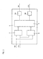
- a first possible embodiment of the signal period variation unit 6 will be explained in more detail with reference to the illustration in Figure 2. in this connection the embodiment shown is particularly in connection with the Position measuring device according to FIG 1 can be used.
- the of the Signal generation unit 5 generated analog incremental signals SIN, COS are supplied to the signal period variation unit 6 and arrive on the input side to a first and second interpolator unit 9, 10.
- a multiple division the analog incremental signals SIN, COS takes place in the second interpolator unit 10 Counting the respective signal zero crossings.
- On the output side deliver the two interpolator 9, 10 each have a digital word, which to a downstream memory module 11 is passed or for addressing the same serves.
- the memory module 11 in turn contains a number of conversion tables for different variation factors n of the signal periods the analog incremental signals SIN, COS. Per variation factor n Consequently, a corresponding conversion table is available. Depending on the desired magnification of the signal period is via the conversion table each position value of the two signals resulting from the gives two given digital words, a certain changed position value assigned, so that in each case a waveform with an enlarged signal period results.
- the memory module 11 supplies after Such signal processing control signals for downstream D / A converter, the quasi-analog sinusoidal and cosinusoidal incremental signals Create SIN ', COS'. These modified incremental signals SIN ', COS' are then transferred to the evaluation unit.
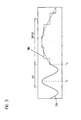
- FIG. 3 An illustration of the waveform of at least one analog incremental signal SIN shortly before or shortly after the variation of the signal period SP is shown in FIG.
- the analog incremental signal SIN delivered by the signal generation unit 5 can be seen, whose signal period SP is to be changed.
- the request to increase the signal period SP takes place.
- the incremental signal SIN 'modified in signal period SP' and frequency is then transmitted to the evaluation unit.
- the switching time t U is in this case selected to be defined in such a way that switching to a different signal period SP 'takes place at a zero crossing of the analog incremental signal SIN.
- the quantization of the modified incremental signal SIN ' is shown in greatly exaggerated form; dot-dashed is the ideal sinusoidal shape of the incremental signal SIN 'drawn.
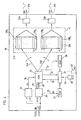
- a second embodiment of a suitable signal period variation unit 26 is shown in a schematic representation in FIG.
- this variant is suitable in conjunction with a position measuring device designed as an interferometer.
- the measures explained in the first exemplary embodiment can also be implemented in conjunction with the following exemplary embodiment.
- the following description also describes various correction means for eliminating different errors which may occur during position determination.
- the incremental signals SIN, COS delivered by the position measuring device or by the interferometer are supplied to an interpolator unit 29 and a direction detection unit 23 in the signal period variation unit 26.
- an electronic further subdivision of the input signals SIN, COS takes place in a known manner, ie the interpolator unit 29 supplies on the output side interpolated digital signals DS or square pulses with a higher frequency than the input signals SIN, COS.
- a direction signal RS is generated with respect to the direction of movement of the two mutually movable parts whose relative position is to be determined.
- the interpolated digital signals DS as well as the direction signal RS are supplied via the data lines 36 and 38 of an address counter unit 24.
- a change in the address counter value AZW In the case of a forward movement, the address counter value AZW is, for example, incremented or incremented by one value for each rectangular pulse; in the case of the backward movement takes place at each square pulse a reduction of the address counter value AZW or a count back. If no rectangular pulse or digital signal DS from the interpolator unit 29 is applied, the address counter value AZW remains unchanged.
- a memory module 41 Downstream of the address counter unit 24, a memory module 41 is provided, which in the illustrated embodiment contains two conversion tables 21A, 21B in the form of a sine or cosine table.
- the conversion tables 21A, 21B each consisting of k addressed table regions 21A 1 - 21A k, 21B 1 - 21B k, where in the respective k table areas 21A 1 - k 21A, 21B 1 - 21B k in digital form, the signal amplitude values of at least one Period of a sine or cosine function are stored.
- the individual k table areas 21A 1 - 21A k , 21B 1 - 21B k can be controlled by the address counter unit 24 via address pointers 34A, 34B.
- the signal amplitude values of the table regions 21A 1 - 21A k , 21B 1 - 21B k driven in this way are then respectively transmitted to D / A converter units 22A, 22B, which in turn generate the analog incremental signals SIN ', COS', which are transmitted to the evaluation unit .
- the D / A converter units 22A, 22B can furthermore each be followed by suitable filter electronics (not shown) which suitably smooth the resulting analog incremental signals SIN ', COS' prior to transmission to the evaluation unit.
- an output of the address counter unit 24 is provided, are addressed via the two address pointers 34A, 34B, each in turn a conversion table 21A, 21 B control.
- the address counter unit could have on the output side only a single address pointer, which in turn drives only a single conversion table.
- the table areas of the combined conversion table to be selected in this case have twice the memory width compared to the first exemplary embodiment, so that the digital signal amplitude values of the sine and cosine functions can be stored there in combined form.
- two address pointers of the address counter unit point to a single conversion table in which, for example, only the digital signal amplitude values of a sine function are stored.
- a phase offset of 90 ° is specified between the two address pointers, so that in this way the phase-shifted signal amplitude values of a sine and a cosine function for the output signals can be transferred to the downstream D / A converters.
- the output-side variable signal periods SP 'of the analog incremental signals SIN', COS ' are generated in the embodiment shown in the manner explained below.
- signal periods SP 'of the analog incremental signals SIN', COS 'of 1 .mu.m, 2 .mu.m, 4 .mu.m and 10 .mu.m can be generated in the example on the output side; Consequently, the signal periods SP 'available on the output side are each in an integer relationship to each other.
- the digital signal amplitude values of a sine or cosine function with a signal period which represents the smallest common multiple of the output signal periods SP ', ie sine and cosine functions, are then stored in this example a signal period of 20 ⁇ m.
- the address pointers 34A, 34B are incremented each square pulse of the interpolator 29 with different actuation step widths, that is, different table areas 21A 1 - 21A k, 21B 1 - 21B k of the conversion tables 21A, addressed 21B. If, on the output side, for example, analog incremental signals SIN ', COS' with the signal period 10 ⁇ m are desired, then the drive step size for each rectangular pulse is 2 steps, ie after table region 21A 1 the table area 21A 3 is then driven by the address pointer required signal period of 4 .mu.m is the drive step size for the address pointer 34A, 34B 5 table steps etc ..
- Each signal period variation factor n is therefore associated with a certain drive step size of the address pointers 34A, 34B.
- the signal period variation unit 26 consequently stores the digital signal amplitude values of sine and / or cosine functions corresponding to the largest output-side desired signal period SP 'of the analog incremental signals SIN', COS ' but in an integer ratio to all desired signal periods SP 'of the analog incremental signals SIN', COS 'is.
- variable signal period of analog incremental signals may be similar to those described above Embodiment of Figure 2 are provided, in the corresponding Memory module of the signal period variation unit for each desired Resolution or for each required output signal period a separate conversion table for the sine and / or cosine function store.
- the two mentioned options also be suitably combined with each other.
- certain integer signal period ratios to realize about the explained with reference to Figure 4 variant, while others Signal periods of the analog incremental signals on the basis of separate Conversion tables as explained above be realized etc ..
- the signal period variation unit 26 of this embodiment further includes various correction means for eliminating errors in the position determination or signal period variation.
- an input counter unit 25, a flow counter unit 38 and a processor unit 27 may be referred to as correction means, the mode of operation of which is explained below within the signal period variation unit 26.
- the output signals of the above-mentioned interpolator unit 29 in the form of digital signals DS or rectangular pulses are also supplied to the input counter unit 25 via the data line 28, ie the current input counter value EZW represents the number of previously transmitted rectangular pulses of the interpolator unit 29.
- SPM EZW * ⁇ air /8th ⁇ air / 8 represents the signal period SP of the input signals SIN, COS.
- the determined pass counter value DZW thus represents the number of passes made so far by the address pointers 34A, 34B through the conversion tables 21A, 21B or the proportion of entire signal periods at the current actual position measured value IPM.
- a comparison of the two measured values SPM and IPM is then carried out via the processor unit 27. If a deviation between the two measured values SPM and IPM is detected, then the address counter unit 24 is actuated by the processor unit 27 via the data line 30 in such a way that the address counter value AZW is corrected or reduced in a corrective manner. As a result of the suitably increased or reduced address counter value AZW, the address pointers 34A, 34B in turn drive other table areas 21A 1 - 21A k , 21B 1 - 21B k of the conversion tables 21A, 21B and thus generate analog incremental signals SIN ', COS'.
- a first source of error lies in the non-integer ratio of the laser wavelength ⁇ used, ie the division standard used, to the usual units, such as the predetermined signal period SP 'of the analog incremental signals SIN', COS ', which are given for example in metric form. This results in each pass of a conversion table 21A, 21 B and the generation of the desired output signal period SP 'an error in the detected actual position measured value IPM, among other things, on the number k of the designated table spaces 21A 1 - 21A k, 21B 1 - 21B k depends.
- a further improvement results when such a correction of the address counter value AZW already takes place with a deviation from the nominal and actual position measured value SPM, IPM which is greater than half the minimum control step size. This makes it possible to achieve that the maximum error in the position measurement is in the order of magnitude of half the drive increment.
- a further increase of the measuring accuracy or further error minimization By the factor j can be achieved, if in the conversion tables 21A, 21B is an integer multiple j of the required signal amplitude values is stored, i. j signal periods of the corresponding sine or Cosine function. In the limit case could be such a number j of signal periods be stored, that they correspond to the complete measuring length.
- the cause of the error minimization lies with such Procedure in that in the case of several stored signal periods of non-integer Remainder from the relationship between the signal periods and the Wavelength is smaller than e.g. in the case of only a single signal period. Overall, this results in a factor j smaller cumulative error.
- a second source of error lies in the fluctuating environmental conditions during the measurement, such as air pressure p, temperature T and humidity f.
- the respective gas composition in the measuring chamber counts.
- the parameters p, T, f and possibly also the gas composition also change the wavelength ⁇ air of the radiation source used in the interferometer, ie the signal period SP of the incremental signals SIN, COS.
- it is not guaranteed without correction that the desired relationship SP ' n * SP between the input and output signal periods SP and SP' applies. For this reason, in the embodiment of the signal period variation unit 26 shown in FIG.
- the environmental parameters p, T, f and possibly also the gas composition are included in the determination of SPM according to Eq. (1) used wavelength ⁇ air . Therefore, by means of suitable detection means 39, the environmental parameters such as air temperature, humidity and pressure and possibly also the gas composition are detected, supplied via the data line 33 to the processor unit 27 and taken into account in the determination of the desired position measured value SPM. For this purpose, in the processor unit 27, the wavelength ⁇ air is continuously updated via the known noble formula and taken into account in the determination of SPM.
- the analog incremental signals SIN ', COS' then have at most one error, which is of the order of resolution of a table area 21A 1 - 21A k , 21B 1 - 21B k or half a table area, depending on the selected correction step size.
- the refractive index of the air in the measuring chamber via a Refractive index determination unit, e.g. via a refractometer directly to determine and supply the processor unit 27 for further processing.
- the processor unit 27 additionally draws the output signals of the refractometer for determining the current nominal position measured value.
- a data memory 40 is schematically indicated in FIG. 4, in which measurement-system-specific compensation data KD are stored.
- this involves machine-specific correction data relating to spindle pitch errors, guide errors, thermal errors, etc., which are likewise fed to the processor unit 27 during the position determination, similar to the environmental parameters p, T, f.
- the position measuring device according to the invention embody.
Landscapes
- Physics & Mathematics (AREA)
- General Physics & Mathematics (AREA)
- Transmission And Conversion Of Sensor Element Output (AREA)
- Length Measuring Devices With Unspecified Measuring Means (AREA)
- Vehicle Body Suspensions (AREA)
- Basic Packing Technique (AREA)
- Length Measuring Devices By Optical Means (AREA)
- Devices For Conveying Motion By Means Of Endless Flexible Members (AREA)
- Die Bonding (AREA)
Applications Claiming Priority (5)
| Application Number | Priority Date | Filing Date | Title |
|---|---|---|---|
| DE19715742 | 1997-04-16 | ||
| DE19715742 | 1997-04-16 | ||
| DE19742317 | 1997-09-25 | ||
| DE19742317 | 1997-09-25 | ||
| EP98106294A EP0872714B1 (fr) | 1997-04-16 | 1998-04-07 | Dispositif pour déterminer la position ainsi que la procédure de son opération |
Related Parent Applications (1)
| Application Number | Title | Priority Date | Filing Date |
|---|---|---|---|
| EP98106294A Division EP0872714B1 (fr) | 1997-04-16 | 1998-04-07 | Dispositif pour déterminer la position ainsi que la procédure de son opération |
Publications (4)
| Publication Number | Publication Date |
|---|---|
| EP1610096A2 true EP1610096A2 (fr) | 2005-12-28 |
| EP1610096A3 EP1610096A3 (fr) | 2006-04-26 |
| EP1610096B1 EP1610096B1 (fr) | 2007-06-27 |
| EP1610096B2 EP1610096B2 (fr) | 2012-09-05 |
Family
ID=26035792
Family Applications (2)
| Application Number | Title | Priority Date | Filing Date |
|---|---|---|---|
| EP98106294A Expired - Lifetime EP0872714B1 (fr) | 1997-04-16 | 1998-04-07 | Dispositif pour déterminer la position ainsi que la procédure de son opération |
| EP05016369A Expired - Lifetime EP1610096B2 (fr) | 1997-04-16 | 1998-04-07 | Dispositif de mesure de position et procédé de fonctionnement d'un dispositif de mesure de position |
Family Applications Before (1)
| Application Number | Title | Priority Date | Filing Date |
|---|---|---|---|
| EP98106294A Expired - Lifetime EP0872714B1 (fr) | 1997-04-16 | 1998-04-07 | Dispositif pour déterminer la position ainsi que la procédure de son opération |
Country Status (5)
| Country | Link |
|---|---|
| US (2) | US6097318A (fr) |
| EP (2) | EP0872714B1 (fr) |
| JP (1) | JP4334034B2 (fr) |
| AT (2) | ATE302404T1 (fr) |
| DE (3) | DE19815438B4 (fr) |
Families Citing this family (16)
| Publication number | Priority date | Publication date | Assignee | Title |
|---|---|---|---|---|
| DE19861259C5 (de) * | 1997-04-16 | 2010-09-02 | Dr. Johannes Heidenhain Gmbh | Positionsmeßeinrichtung und Verfahren zum Betrieb einer Positionsmeßeinrichtung |
| DE19815438B4 (de) * | 1997-04-16 | 2007-08-02 | Dr. Johannes Heidenhain Gmbh | Positionsmeßeinrichtung und Verfahren zum Betrieb einer Positionsmeßeinrichtung |
| DE10054075A1 (de) * | 2000-10-31 | 2002-05-08 | Heidenhain Gmbh Dr Johannes | Verfahren zur Positionsbestimmung und Positionsmesseinrichtung |
| US7031031B1 (en) * | 2000-12-06 | 2006-04-18 | Dr. Johannes Heidenhain Gmbh | Position measuring system |
| EP1399715B1 (fr) * | 2001-06-27 | 2006-11-22 | Fraunhofer-Gesellschaft zur Förderung der angewandten Forschung e.V. | Procede et dispositif permettant de preparer un signal d'un capteur de position en vue de sa transmission a une unite d'evaluation |
| JP3942971B2 (ja) * | 2002-07-08 | 2007-07-11 | 株式会社ソディック | 移動体駆動装置 |
| DE10232024A1 (de) * | 2002-07-16 | 2004-01-29 | Ina-Schaeffler Kg | Vorrichtung und Verfahren zur Aufbereitung analoger Signale |
| US20050019404A1 (en) * | 2003-06-30 | 2005-01-27 | Hsing-Wen Sung | Drug-eluting biodegradable stent |
| ES2295618T3 (es) | 2002-09-25 | 2008-04-16 | Dr. Johannes Heidenhain Gmbh | Metodo para el accionamiento de un dispositivo de medicion de la posicion y dispositivo de medicion de la posicion adecuada para el mismo. |
| DE10313518A1 (de) | 2003-03-25 | 2004-10-14 | Hübner Elektromaschinen AG | Positionsmessverfahren und Positionsmesssystem zur Signalperioden-Vervielfachung |
| EP2138916B1 (fr) * | 2008-06-24 | 2014-05-07 | SICK STEGMANN GmbH | Système de mesure de position |
| JP5756267B2 (ja) | 2010-09-03 | 2015-07-29 | オリンパス株式会社 | エンコーダ用信号処理回路 |
| DE102011083042A1 (de) * | 2010-11-29 | 2012-05-31 | Dr. Johannes Heidenhain Gmbh | Überwachungseinheit und Verfahren zur Überwachung von Positionssignalen inkrementaler Positionsmesseinrichtungen |
| ES2656388T3 (es) * | 2015-07-27 | 2018-02-27 | Dr. Johannes Heidenhain Gmbh | Dispositivo de medición de posición y procedimiento para su funcionamiento |
| US10184807B2 (en) * | 2016-09-26 | 2019-01-22 | Infineon Technologies Ag | True-power-on and diagnostic-capable incremental interface for angular sensors |
| CN120315371A (zh) * | 2025-02-28 | 2025-07-15 | 清华大学 | 数控机床主轴热误差建模方法及装置 |
Family Cites Families (21)
| Publication number | Priority date | Publication date | Assignee | Title |
|---|---|---|---|---|
| DE1231911B (de) † | 1964-04-11 | 1967-01-05 | Wenczler & Heidenhain | Einrichtung zum Messen von Strecken oder Teilen von Kreisen mittels Impulszaehlung |
| DE2729697A1 (de) * | 1977-07-01 | 1979-01-04 | Heidenhain Gmbh Dr Johannes | Verfahren zur interpolation |
| DE3024716C2 (de) * | 1980-06-30 | 1986-10-23 | Dr. Johannes Heidenhain Gmbh, 8225 Traunreut | Digitales Längen- oder Winkelmeßsystem |
| DE3036830C2 (de) † | 1980-09-30 | 1987-01-08 | Dr. Johannes Heidenhain Gmbh, 8225 Traunreut | Verfahren zur Korrektur von Meßwerten bei einem digitalen elektrischen Längen- oder Winkelmeßsystem |
| DE3202356C1 (de) * | 1982-01-26 | 1983-08-11 | Dr. Johannes Heidenhain Gmbh, 8225 Traunreut | Einrichtung zum Unterteilen von periodischen analogen Signalen |
| DE3224005A1 (de) † | 1982-06-26 | 1984-01-05 | Dr. Johannes Heidenhain Gmbh, 8225 Traunreut | Laengen- oder winkelmesssystem |
| CH666348A5 (de) † | 1984-04-12 | 1988-07-15 | Heinz Rieder | Verfahren zum auswerten von messsignalen, die durch abtastung eines inkrementalmassstabes mit einer abtasteinheit erhalten werden und messeinrichtung zur durchfuehrung dieses verfahrens. |
| DE3417015C2 (de) † | 1984-05-09 | 1986-03-13 | Preibisch, Herbert, Dr.-Ing., 8000 München | Interpolationsverfahren |
| DE3514155A1 (de) * | 1985-04-19 | 1986-10-23 | Dr. Johannes Heidenhain Gmbh, 8225 Traunreut | Verfahren und einrichtung zur regelung des tastverhaeltnisses wenigstens eines elektrischen signals |
| DE3608884A1 (de) * | 1986-03-17 | 1987-09-24 | Mitec Moderne Ind Gmbh | Messanordnung |
| JPH01502702A (ja) † | 1987-03-24 | 1989-09-14 | ラディク,トゥイヌ アルボウィッチ | 光ヘッドを作動させるための磁電機構 |
| DE3772989D1 (de) † | 1987-07-06 | 1991-10-17 | Rsf Elektronik Gmbh | Inkrementales lagemesssystem. |
| WO1989011080A1 (fr) † | 1988-05-10 | 1989-11-16 | Siemens Aktiengesellschaft | Capteur angulaire a position codee |
| JPH0299826A (ja) * | 1988-10-07 | 1990-04-11 | Matsushita Electric Ind Co Ltd | エンコーダの信号処理装置 |
| DE4011411C2 (de) * | 1990-04-09 | 1993-09-30 | Heidenhain Gmbh Dr Johannes | Inkrementales Positionsmeßsystem |
| JPH04229702A (ja) | 1990-06-20 | 1992-08-19 | Canon Inc | 信号処理方法及び装置、並びにこれを用いた変位検出装置等のシステム |
| JP3313750B2 (ja) | 1992-01-21 | 2002-08-12 | キヤノン株式会社 | 信号処理装置及びこれを用いた装置 |
| DE4229575C1 (de) † | 1992-09-04 | 1993-11-25 | Heidenhain Gmbh Dr Johannes | Verfahren bei Längen- oder Winkelmeßeinrichtungen |
| DE4443898C2 (de) † | 1994-12-09 | 1996-09-26 | Heidenhain Gmbh Dr Johannes | Positionsmeßverfahren und Positionsmeßeinrichtung |
| DE19601275C2 (de) † | 1996-01-16 | 2000-03-02 | Heidenhain Gmbh Dr Johannes | Meßeinrichtung zur Ermittlung der Abmessungen von Objekten |
| DE19815438B4 (de) * | 1997-04-16 | 2007-08-02 | Dr. Johannes Heidenhain Gmbh | Positionsmeßeinrichtung und Verfahren zum Betrieb einer Positionsmeßeinrichtung |
-
1998
- 1998-04-07 DE DE19815438A patent/DE19815438B4/de not_active Expired - Fee Related
- 1998-04-07 DE DE59814046T patent/DE59814046D1/de not_active Expired - Lifetime
- 1998-04-07 EP EP98106294A patent/EP0872714B1/fr not_active Expired - Lifetime
- 1998-04-07 DE DE59813001T patent/DE59813001D1/de not_active Expired - Lifetime
- 1998-04-07 EP EP05016369A patent/EP1610096B2/fr not_active Expired - Lifetime
- 1998-04-07 AT AT98106294T patent/ATE302404T1/de not_active IP Right Cessation
- 1998-04-07 AT AT05016369T patent/ATE365906T1/de not_active IP Right Cessation
- 1998-04-14 JP JP10294498A patent/JP4334034B2/ja not_active Expired - Fee Related
- 1998-04-16 US US09/061,311 patent/US6097318A/en not_active Expired - Lifetime
-
2000
- 2000-07-05 US US09/609,618 patent/US6265992B1/en not_active Expired - Fee Related
Also Published As
| Publication number | Publication date |
|---|---|
| ATE302404T1 (de) | 2005-09-15 |
| US6097318A (en) | 2000-08-01 |
| US6265992B1 (en) | 2001-07-24 |
| EP1610096B2 (fr) | 2012-09-05 |
| DE19815438B4 (de) | 2007-08-02 |
| EP0872714A1 (fr) | 1998-10-21 |
| DE19815438A1 (de) | 1998-10-22 |
| ATE365906T1 (de) | 2007-07-15 |
| JP4334034B2 (ja) | 2009-09-16 |
| DE59813001D1 (de) | 2005-09-22 |
| JPH112515A (ja) | 1999-01-06 |
| DE59814046D1 (de) | 2007-08-09 |
| EP1610096A3 (fr) | 2006-04-26 |
| EP0872714B1 (fr) | 2005-08-17 |
| EP1610096B1 (fr) | 2007-06-27 |
Similar Documents
| Publication | Publication Date | Title |
|---|---|---|
| EP0872714B1 (fr) | Dispositif pour déterminer la position ainsi que la procédure de son opération | |
| DE19712622B4 (de) | Anordnung und Verfahren zur automatischen Korrektur fehlerbehafteter Abtastsignale inkrementaler Positionsmeßeinrichtungen | |
| EP0509979B1 (fr) | Dispositif de mesure de positions photo-électronique | |
| DE19748802B4 (de) | Optische Positionsmeßeinrichtung | |
| DE69117219T2 (de) | Verfahren und Apparat zur Verarbeitung von Signalen, und ein System wie z.B. eine Vorrichtung zur Bestimmung von Verschiebungen, die diese verwendet | |
| DE69321854T2 (de) | Signalverarbeitungsvorrichtung und -verfahren sowie diese verwendende Versatzerfassungsvorrichtung | |
| EP1606590B1 (fr) | Procede de mesure de position et systeme de mesure de position destines a la multiplication de periodes de signaux | |
| EP0390770B1 (fr) | Méthode de correction électronique d'erreur de position pour un système de mesure incrémentiel et système de mesure pour mettre en oeuvre ce procédé | |
| EP1195579B1 (fr) | Procédé de détermination de la position absolue | |
| EP3124920B1 (fr) | Dispositif de mesure de position et son procédé de fonctionnement | |
| EP1126248B1 (fr) | Dispositif pour déterminer la position ainsi que la procédure de son opération | |
| DE3202356C1 (de) | Einrichtung zum Unterteilen von periodischen analogen Signalen | |
| EP0763715A2 (fr) | Dispositif pour filtrer des harmoniques de signaux | |
| DE19861259B4 (de) | Positionsmeßeinrichtung und Verfahren zum Betrieb einer Positionsmeßeinrichtung | |
| EP0866391A1 (fr) | Méthode et dispositif pour la transmission de données entre un appareil de mesure de position et une unité de traitement | |
| DE3123002A1 (de) | Verfahren und einrichtung zur drehzahlmessung einer mit einem rotierenden impulsgeber gekuppelten welle | |
| DD251003A5 (de) | Geraet zur messung der geschwindigkeit eines beweglichen koerpers | |
| DE69519767T2 (de) | Sägezahnsignalgenerator und Signalinterpolationseinrichtung, welche diesen verwendet | |
| EP0932819B1 (fr) | Indicateur optique de position | |
| DE2309698C3 (de) | Vorrichtung zur Ansteuerung und Stabilisation von Längenpositionen | |
| EP0291763B1 (fr) | Système de commande automatique pour des couteaux | |
| DE2641795C3 (de) | Vorrichtung zum Messen und Regeln von Drücken bzw. Differenzdrücken | |
| DE10200587A1 (de) | Verfahren und Vorrichtung zur inkrementalen Positionsbestimmung | |
| WO2001031409A9 (fr) | Systeme et procede pour commander une unite de positionnement, notamment des mecanismes de commande dans des machines-outils, et dispositif de melange de phases | |
| DE69116367T2 (de) | Verfahren und Vorrichtung zur Impulserzeugung |
Legal Events
| Date | Code | Title | Description |
|---|---|---|---|
| PUAI | Public reference made under article 153(3) epc to a published international application that has entered the european phase |
Free format text: ORIGINAL CODE: 0009012 |
|
| AC | Divisional application: reference to earlier application |
Ref document number: 0872714 Country of ref document: EP Kind code of ref document: P |
|
| AK | Designated contracting states |
Kind code of ref document: A2 Designated state(s): AT BE CH CY DE DK ES FI FR GB GR IE IT LI LU MC NL PT SE |
|
| AX | Request for extension of the european patent |
Extension state: AL LT LV MK RO SI |
|
| PUAL | Search report despatched |
Free format text: ORIGINAL CODE: 0009013 |
|
| AK | Designated contracting states |
Kind code of ref document: A3 Designated state(s): AT BE CH CY DE DK ES FI FR GB GR IE IT LI LU MC NL PT SE |
|
| AX | Request for extension of the european patent |
Extension state: AL LT LV MK RO SI |
|
| 17P | Request for examination filed |
Effective date: 20061026 |
|
| AKX | Designation fees paid |
Designated state(s): AT CH DE FR GB IT LI |
|
| GRAP | Despatch of communication of intention to grant a patent |
Free format text: ORIGINAL CODE: EPIDOSNIGR1 |
|
| GRAS | Grant fee paid |
Free format text: ORIGINAL CODE: EPIDOSNIGR3 |
|
| GRAA | (expected) grant |
Free format text: ORIGINAL CODE: 0009210 |
|
| AC | Divisional application: reference to earlier application |
Ref document number: 0872714 Country of ref document: EP Kind code of ref document: P |
|
| AK | Designated contracting states |
Kind code of ref document: B1 Designated state(s): AT CH DE FR GB IT LI |
|
| REG | Reference to a national code |
Ref country code: GB Ref legal event code: FG4D Free format text: NOT ENGLISH |
|
| GBT | Gb: translation of ep patent filed (gb section 77(6)(a)/1977) |
Effective date: 20070627 |
|
| REG | Reference to a national code |
Ref country code: CH Ref legal event code: NV Representative=s name: TROESCH SCHEIDEGGER WERNER AG Ref country code: CH Ref legal event code: EP |
|
| REF | Corresponds to: |
Ref document number: 59814046 Country of ref document: DE Date of ref document: 20070809 Kind code of ref document: P |
|
| ET | Fr: translation filed | ||
| PLBI | Opposition filed |
Free format text: ORIGINAL CODE: 0009260 |
|
| PLBI | Opposition filed |
Free format text: ORIGINAL CODE: 0009260 |
|
| 26 | Opposition filed |
Opponent name: SCHAEFFLER KG Effective date: 20080305 Opponent name: BAUMER HUEBNER GMBH Effective date: 20080227 |
|
| 26 | Opposition filed |
Opponent name: BAUMER HUEBNER GMBH Effective date: 20080227 Opponent name: SICK STEGMANN GMBH Effective date: 20080318 Opponent name: SCHAEFFLER KG Effective date: 20080305 |
|
| PLAX | Notice of opposition and request to file observation + time limit sent |
Free format text: ORIGINAL CODE: EPIDOSNOBS2 |
|
| PLAB | Opposition data, opponent's data or that of the opponent's representative modified |
Free format text: ORIGINAL CODE: 0009299OPPO |
|
| PLBB | Reply of patent proprietor to notice(s) of opposition received |
Free format text: ORIGINAL CODE: EPIDOSNOBS3 |
|
| PG25 | Lapsed in a contracting state [announced via postgrant information from national office to epo] |
Ref country code: AT Free format text: LAPSE BECAUSE OF NON-PAYMENT OF DUE FEES Effective date: 20080407 |
|
| PGFP | Annual fee paid to national office [announced via postgrant information from national office to epo] |
Ref country code: FR Payment date: 20090414 Year of fee payment: 12 Ref country code: IT Payment date: 20090429 Year of fee payment: 12 |
|
| REG | Reference to a national code |
Ref country code: FR Ref legal event code: ST Effective date: 20101230 |
|
| PG25 | Lapsed in a contracting state [announced via postgrant information from national office to epo] |
Ref country code: IT Free format text: LAPSE BECAUSE OF NON-PAYMENT OF DUE FEES Effective date: 20100407 |
|
| APAH | Appeal reference modified |
Free format text: ORIGINAL CODE: EPIDOSCREFNO |
|
| APBM | Appeal reference recorded |
Free format text: ORIGINAL CODE: EPIDOSNREFNO |
|
| APBP | Date of receipt of notice of appeal recorded |
Free format text: ORIGINAL CODE: EPIDOSNNOA2O |
|
| APBU | Appeal procedure closed |
Free format text: ORIGINAL CODE: EPIDOSNNOA9O |
|
| PG25 | Lapsed in a contracting state [announced via postgrant information from national office to epo] |
Ref country code: FR Free format text: LAPSE BECAUSE OF NON-PAYMENT OF DUE FEES Effective date: 20100430 |
|
| PUAH | Patent maintained in amended form |
Free format text: ORIGINAL CODE: 0009272 |
|
| STAA | Information on the status of an ep patent application or granted ep patent |
Free format text: STATUS: PATENT MAINTAINED AS AMENDED |
|
| PGFP | Annual fee paid to national office [announced via postgrant information from national office to epo] |
Ref country code: GB Payment date: 20120419 Year of fee payment: 15 |
|
| 27A | Patent maintained in amended form |
Effective date: 20120905 |
|
| AK | Designated contracting states |
Kind code of ref document: B2 Designated state(s): AT CH DE FR GB IT LI |
|
| REG | Reference to a national code |
Ref country code: CH Ref legal event code: AEN Free format text: AUFRECHTERHALTUNG DES PATENTES IN GEAENDERTER FORM |
|
| REG | Reference to a national code |
Ref country code: DE Ref legal event code: R102 Ref document number: 59814046 Country of ref document: DE Effective date: 20120905 |
|
| PGFP | Annual fee paid to national office [announced via postgrant information from national office to epo] |
Ref country code: CH Payment date: 20130422 Year of fee payment: 16 Ref country code: DE Payment date: 20130419 Year of fee payment: 16 |
|
| GBPC | Gb: european patent ceased through non-payment of renewal fee |
Effective date: 20130407 |
|
| PG25 | Lapsed in a contracting state [announced via postgrant information from national office to epo] |
Ref country code: GB Free format text: LAPSE BECAUSE OF NON-PAYMENT OF DUE FEES Effective date: 20130407 |
|
| REG | Reference to a national code |
Ref country code: DE Ref legal event code: R119 Ref document number: 59814046 Country of ref document: DE |
|
| REG | Reference to a national code |
Ref country code: CH Ref legal event code: PL |
|
| REG | Reference to a national code |
Ref country code: DE Ref legal event code: R119 Ref document number: 59814046 Country of ref document: DE Effective date: 20141101 |
|
| PG25 | Lapsed in a contracting state [announced via postgrant information from national office to epo] |
Ref country code: DE Free format text: LAPSE BECAUSE OF NON-PAYMENT OF DUE FEES Effective date: 20141101 Ref country code: LI Free format text: LAPSE BECAUSE OF NON-PAYMENT OF DUE FEES Effective date: 20140430 Ref country code: CH Free format text: LAPSE BECAUSE OF NON-PAYMENT OF DUE FEES Effective date: 20140430 |