EP1610124A2 - Verfahren zur Probenaufgabe für ein Probenanalysegerät und Linerhandhabungssystem - Google Patents
Verfahren zur Probenaufgabe für ein Probenanalysegerät und Linerhandhabungssystem Download PDFInfo
- Publication number
- EP1610124A2 EP1610124A2 EP05005558A EP05005558A EP1610124A2 EP 1610124 A2 EP1610124 A2 EP 1610124A2 EP 05005558 A EP05005558 A EP 05005558A EP 05005558 A EP05005558 A EP 05005558A EP 1610124 A2 EP1610124 A2 EP 1610124A2
- Authority
- EP
- European Patent Office
- Prior art keywords
- liner
- transport head
- sample
- liners
- feeding device
- Prior art date
- Legal status (The legal status is an assumption and is not a legal conclusion. Google has not performed a legal analysis and makes no representation as to the accuracy of the status listed.)
- Granted
Links
Images


Classifications
-
- G—PHYSICS
- G01—MEASURING; TESTING
- G01N—INVESTIGATING OR ANALYSING MATERIALS BY DETERMINING THEIR CHEMICAL OR PHYSICAL PROPERTIES
- G01N30/00—Investigating or analysing materials by separation into components using adsorption, absorption or similar phenomena or using ion-exchange, e.g. chromatography or field flow fractionation
- G01N30/02—Column chromatography
- G01N30/04—Preparation or injection of sample to be analysed
- G01N30/06—Preparation
- G01N30/12—Preparation by evaporation
-
- G—PHYSICS
- G01—MEASURING; TESTING
- G01N—INVESTIGATING OR ANALYSING MATERIALS BY DETERMINING THEIR CHEMICAL OR PHYSICAL PROPERTIES
- G01N30/00—Investigating or analysing materials by separation into components using adsorption, absorption or similar phenomena or using ion-exchange, e.g. chromatography or field flow fractionation
- G01N30/02—Column chromatography
- G01N30/04—Preparation or injection of sample to be analysed
- G01N30/24—Automatic injection systems
Definitions
- the invention relates to a method for sample application for a Sample analyzer and a liner handling system as well as components hereof.
- samples are transferred for sample analysis Feeding devices introduced in the gas chromatograph, the samples of changeable, by means of carrier gas permeable, tubular Sample containers, so-called liners are recorded.
- Usual liners can Although specifically designed with regard to the inclusion of the samples inside them or be equipped, but are outside - possibly up to an exit side Constriction - cylindrical and smooth and in general as glass or Standardized stainless steel tubes.
- the object of the invention is a method for sample application for a Sample analyzer to provide an automatic liner change without the Use specially trained liner allows.
- the illustrated in Fig. 1 cold application device K for a gas chromatograph comprises a base plate 1 with a passage opening 2, wherein with Distance to the base plate 1, a liner holder 3 by means of screws 4 solvable is attached.
- the liner holder 3 comprises a round, perforated support plate 5, the a central receiving opening for a receiving pot 6 mounted therein. Lying on the support plate 5 are several, radially up to the pot 6 extending sleeves 7, which have rectangular or round cross-section can, are secured by means of screws 8 and nuts 9.
- a radially displaceable piston 10 which by means of a on the associated screw 8 supporting spring 11 is biased radially inwardly.
- the Sleeves 7 are provided on the upper side with a slot 12.
- a clamping jaw 13 which over in the slot 12 running Guide blocks 14 is radially displaceable.
- the respective jaw 13 is connected to the associated piston 10 via screws 15, which are also the guide stones 14 wear.
- On the outer periphery of the pot 6 is one with a Pressure medium, in particular compressed air, acted upon circumferential, outside the region of the sleeves 7 from the outside closed groove 16 through which the piston 10 against the force of the springs 11 acted upon and thus together with the Clamping jaws 13 are displaced radially outward.
- the pot 6 is opened with holes 17 opening into its interior Carrier gas supply or Spülgasabschreib and bottom side provided with an opening, in which a guide tube 18 is fixed, the bottom side with a Connector 19 is provided. On the guide tube 18 is outside a Heater 20 attached, which extends to the connector 19 and is held by this. In addition, a cooling, not shown provided for example via a Peltier element.
- the cold application device K is for receiving a liner 21, with a transport head 22 is provided, designed.
- the rotationally symmetrical transport head 22 has one in the axial direction arranged therefrom, stepped bore 23 adjacent to the liner side Receiving end is provided with a circumferential groove, which has an O-ring 24th receives.
- the O-ring 24 surrounds the tubular liner 21 with frictional engagement, wherein the inserted into the transport head 22 end of the liner 21 against a shoulder 25th the bore 23 abuts.
- At the periphery of the transport head 22 are axially spaced arranged two circumferential grooves 26 in the area of the holes 17 of the Take pot 6 open. Above, between and below the grooves 26 are O-rings 27 arranged to seal the areas of the grooves 26 against each other.
- the transport head 22 At the end facing away from the liner 21, the transport head 22 with a oblique shoulder 28 provided, with the corresponding bevelled Clamping jaws 13 under the action of acting on the piston 7 Spring bias engage to the slightly conical transport head 22nd in the corresponding slightly conical interior of the pot 6 to Press so that the O-rings 27 in sealing engagement with the inside of the Take pot 6 arrive.
- the liner 21 itself is thereby from the guide tube 18 recorded.
- a pierceable by a syringe needle septum 29 a screwed with a needle guide bore provided needle guide piece 30.
- this is provided with septum 29, but it can also be designed septumlos, such as will be described later.
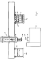
- Fig. 2 shows a structure of a sample preparation and task for a Gas chromatograph G, which provided with a feed device K, the liner 21st can accommodate with transporting heads 22, as above, for example is described. Further, a magazine M1 is present, which in a predetermined Pattern a plurality of blind holes 31 for optionally sealed Receiving liners 21 with transport heads 22 has. Besides, one is Receiving frame M2 for sample container P (vials) provided.
- a so-called Autosamplers S with a horizontally and vertically movable Arm 32 is provided with an unillustrated means for gripping a tip and further with a particular electromagnetically actuated Gripper 33 is equipped for the transport heads 22, the liner 21st handle.
- the gripper 33 is suitably designed so that a Sample preparation or task by means of a syringe by the gripper 33rd can be done through.
- the autosampler S with its gripper 33 in a predetermined Order from the magazine M1 sampleless liner 21 by grabbing her Take transport heads 22 and according to the task K of the Insert gas chromatograph G.
- the autosampler S drives with a syringe according to a predetermined program over one associated, provided with a septum sample container P, removes by means of Syringe a sample, travel with the syringe over the transport head 22 of the Delivery device K located liner, drives the syringe needle through the septum 29 in the liner 21 and is about the syringe needle in the sample to be examined the liner 21 on. Thereafter, the syringe needle is pulled out again while the sample application takes place.
- the liner 21 is at its transport head 22 from the gripper 33 to a circumferential groove 34 detected from the feeding device K removed and stored again in the magazine M1, etc.
- the liner 21 may be once or be used n times, so that this procedure every time or every nth Use of the liner 21 is done.
- the liners 21 can also already be used with a sample to be examined stocked stocked. It is useful if the liner 21 from Magazine M1 can be taken sealed in blind holes to the outside. In this case, the autosampler S removes the liners 21 consecutively, sets she in the task device K, takes them after the sample task again and bring it back to the magazine M1.
- the autosampler S sampleless liner 21 takes the magazine M1, this in corresponding recording heads A of Sample containers P where the liner 21, the sample to be examined record in order to then be used in the task device K.
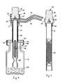
- the liner 21 can in a corresponding receptacle 6 of the Feeding device K and also, as shown, a sample container P used be, with the receiving pot 6 has a stepped bore, so that at inserted transport head 22 adjacent to the mouth of the bore 42 a Annulus and adjacent to the inserted end of the transport head 22 a further, by one of the O-rings 26 opposite the one annulus sealed annular space are formed, each with a on the pot 6 attached gas line 43, 44 are connected to optionally gas through the Sample container P and the liner 21 to lead. Accordingly, too examining substances not only passively (i.e., without gas circulation), but also dynamically on a corresponding phase in the liner 21 for later analysis to be collected.
- the liner 21 is effective as a sampler.
- the liner 21 For sorbing or adsorbing substances to be examined the liner 21, for example, a pack 45, see. Fig. 3, or a collector 46 from a substantially rod-shaped carrier 47 with an active coating 48, Fig. 4, held in the liner 21 via a constriction 49 against falling out will, record.
- a pack 45 see. Fig. 3, or a collector 46 from a substantially rod-shaped carrier 47 with an active coating 48, Fig. 4 held in the liner 21 via a constriction 49 against falling out
- a thin film 53 for example an aluminum foil, sealingly clamped.
- the on the sample container P attachable pot 6 carries on the underside a tube 54 through the cap 51st and the film 53 is pierceable while communicating with at least one septum 52 came in sealing engagement.
- a tube 54 through the liner 21 can be in the sample container P about, as shown in Fig. 4, for optionally dynamic headspace extraction or possibly also for immersion in insert the sample 55 in the sample container P.
- Feeders K which are not for liner 21 with transport heads 22 are equipped, but generally have a threaded connector, which used be attached to a top 60 for the task device K, the Use of liners 21 with transport heads 22 allows.
- the illustrated in Fig. 5 embodiment of such an essay 60th includes underside an internally threaded bore 61 for mounting of the attachment 60 on a feed device K.
- the transport head 22 corresponds essentially that of Figs. 3 and 4, in which case additionally the septum 29th and the screwed needle guide piece 30 are shown in the case The sample application by a syringe are needed while at the Embodiments of FIGS. 3 and 4, the sample holder directly in the sample container P and the sample task directly from the liner 21 done. The latter can in Be related to the essay 60 also provided.
- the attachment 60 has a recess 62 corresponding to that of the Shooting pot 6, which communicates with the bore 61 in connection.
- Carrier gas can over a line 63 and a bore 64 and a circumferential groove 65 of the Transport head 22 are supplied to the interior of the liner 21.
- a tightening of the transport head 22 in the attachment 60 takes place here via a plurality of balls 67 which are radially displaceable in bores 68 of the attachment are arranged.
- Each ball 67 is slanted over a ball 67 towards, in Axial direction of the transport head displaceable piston 69 in the direction of the Shoulder 28 of the transport head 22 slidably.
- the piston 69 is of a Bore 70 is received sealed in the attachment 60 and is in its in Fig. 5th illustrated starting position biased by a spring 71, located on a Cover 72 of the attachment 60 is supported.
- the piston 69 is connected via a line 73 his the ball 67 remote from the side acted upon with compressed air, whereby the Ball 67 in a position on the inclined shoulder 28 of the transport head 22nd is pressed, so that the latter is held in engagement with the recess 62, as long as the pressurization of the piston 69 stops.
- a transport head 22 is septumlos. Instead, the bore 23 by a means of a spring 74 against a sealing ring 75 biased, obliquely to the bore 23 in a bore 76th slidable ball 77 closed, pushed aside by a syringe needle can be.
- the syringe needle comes with the introduction initially on the inlet side one of a cover 78 with a nut 79 clamped sealing ring 80 in sealing engagement.
- the transport head 22 For mounting the ball 77 and cooperating parts the transport head 22 consists of two parts 22a, 22b, along a Sloping surface are joined perpendicular to the bore 76.
- pistons 10 and 69 can also by means of Compressed air to be moved back and forth.
Landscapes
- Physics & Mathematics (AREA)
- Health & Medical Sciences (AREA)
- Life Sciences & Earth Sciences (AREA)
- Chemical & Material Sciences (AREA)
- Analytical Chemistry (AREA)
- Biochemistry (AREA)
- General Health & Medical Sciences (AREA)
- General Physics & Mathematics (AREA)
- Immunology (AREA)
- Pathology (AREA)
- Sampling And Sample Adjustment (AREA)
- Automatic Analysis And Handling Materials Therefor (AREA)
Abstract
wobei die Liner (21), auf die gaseintrittsseitig jeweils ein Transportkopf (22) aufgesetzt ist, der den Liner (21) über eine hiermit reibschlüssige Dichtung (24) hält, an vorbestimmten Plätzen in einem Magazin (M1) und/oder in Probenbehälter (P) eingesteckt angeordnet werden,
eine Wechseleinrichtung (S) verwendet wird, die mit einem Greifer für die Transportköpfe (22) der Liner (21) ausgerüstet ist, und
die Wechseleinrichtung (S) entsprechend einem vorbestimmten Programm den jeweiligen Liner (21) an einem vorbestimmten Platz an seinem Transportkopf (22) ergreift und in die Aufgabeeinrichtung (K) dichtend einsetzt, die Probenaufgabe vorgenommen und anschließend der Liner (21) von der Wechseleinrichtung (S) durch Ergreifen an seinem Transportkopf (22) aus der Aufgabeeinrichtung (K) entfernt wird,
sowie ein Linerhandhabungssystem hierfür.
Description
Claims (19)
- Verfahren zur Probenaufgabe für ein Probenanalysegerät (G), das eine Aufgabeeinrichtung (K) für Proben aufweist, die mit auswechselbaren, zumindest eintrittsseitig rohrförmigen, die Probe aufnehmenden Linern (21) bestückbar ist,
wobei die Liner (21), auf die gaseintrittsseitig jeweils ein Transportkopf (22) aufgesetzt ist, der den Liner (21) über eine hiermit reibschlüssige Dichtung (24) hält, an vorbestimmten Plätzen in einem Magazin (M1) und/oder in Probenbehälter (P) eingesteckt angeordnet werden,
eine Wechseleinrichtung (S) verwendet wird, die mit einem Greifer für die Transportköpfe (22) der Liner (21) ausgerüstet ist, und
die Wechseleinrichtung (S) entsprechend einem vorbestimmten Programm den jeweiligen Liner (21) an einem vorbestimmten Platz an seinem Transportkopf (22) ergreift und in die Aufgabeeinrichtung (K) dichtend einsetzt, die Probenaufgabe vorgenommen und anschließend der Liner (21) von der Wechseleinrichtung (S) durch Ergreifen an seinem Transportkopf (22) aus der Aufgabeeinrichtung (K) entfernt wird. - Verfahren nach Anspruch 1, dadurch gekennzeichnet, daß die Liner (21) von der Wechseleinrichtung (S) in zugehörige Probenbehälter (P) eingesetzt und daraus entnommen werden, die jeweils mit einem Aufnahmekopf (A) für den Transportkopf (22) der Liner (21) versehen sind.
- Verfahren nach Anspruch 1 oder 2, dadurch gekennzeichnet, daß die Transportköpfe (22) der Liner (21) im Magazin (M1) bzw. im Probenbehälter (P) bzw. in der Aufgabeeinrichtung (K) mittels Druckluft gespannt bzw. gelöst wird.
- Verfahren nach einem der Ansprüche 1 bis 3, dadurch gekennzeichnet, daß als Wechseleinrichtung (S) ein Autosampler (S) für die automatische Probenaufgabe mit einem Greifer (33) für die Transportköpfe (22) verwendet wird.
- Verfahren nach einem der Ansprüche 1 bis 4, dadurch gekennzeichnet, daß eine Wechseleinrichtung (S) mit einem elektromagnetisch betätigbaren Greifer (33) für die Transportköpfe (22) verwendet wird.
- Linerhandhabungssystem mit einem Probenanalysegerät (G), das eine Aufgabeeinrichtung (K) für Proben aufweist, die mit auswechselbaren, zumindest eintrittseitig rohrförmigen, die Probe aufnehmenden Linern (21) bestückbar ist, einem Magazin (M1) zur Aufnahme von Linern (21) und einer Wechseleinrichtung (S) zum Wechseln und Transportieren von Linern (21) zwischen der Aufgabeeinrichtung (K), dem Magazin (M1) und gegebenenfalls Probenbehältern (P) entsprechend einem vorbestimmten Programm ,
wobei auf die Liner (21) gaseintrittsseitig jeweils ein Transportkopf (22) aufgesetzt ist, der den Liner (21) über eine hiermit reibschlüssige Dichtung (24) hält,
die Wechseleinrichtung (S) mit einem Greifer für die Transportköpfe (22) der Liner (21) ausgerüstet ist, und
die Aufgabeeinrichtung (K) mit einer Spanneinrichtung zum dichtenden Einspannen des Transportkopfes (22) in die Aufgabeeinrichtung versehen ist. - Transportkopf (22) für einen zumindest eintrittsseitig rohrförmigen Liner (21), mit einer mit einem Dichtungsring (24) versehenen Einstecköffnung (23) zum reibschlüssigen Aufnehmen des Liners (21) und am Außenumfang befindlichen Dichtungsringen (26).
- Transportkopf (22) nach Anspruch 7, gekennzeichnet durch eine schräge Schulter (28) an der der Einstecköffnung (23) abgewandten Seite.
- Transportkopf (22) nach Anspruch 7 oder 8, gekennzeichnet durch eine umlaufende Nut (34) an der der Einstecköffnung (23) abgewandten Seite.
- Transportkopf (22) nach einem der Ansprüche 7 bis 9, dadurch gekennzeichnet, daß wenigstens eine Gaszuführung (17, 26, 42, 64, 65) zur Einstecköffnung (23) vorgesehen ist.
- Transportkopf (22) nach einem der Ansprüche 7 bis 10, dadurch gekennzeichnet, daß die Einstecköffnung (23) als Stufenbohrung durchgehend ausgebildet und eintrittsseitig durch ein Septum (29) oder einer verschiebbare Kugel (77) verschlossen ist.
- Transportkopf (22) nach einem der Ansprüche 8 bis 11, dadurch gekennzeichnet, daß er an der der Einstecköffnung (23) zugewandten Seite der Schulter (28) gestuft und/oder konisch ausgebildet ist.
- Aufgabeeinrichtung für Proben für ein Probenanalysegerät (G), umfassend einen Aufnahmetopf (6) mit einer bodenseitigen Durchtrittsöffnung für einen mit einem von dem Aufnahmetopf (6) aufnehmbaren Transportkopf (22) versehenen, zumindest eintrittsseitig rohrförmigen Liner (21), der von dem Transportkopf (22) reibschlüssig gehalten wird, und eine Spanneinrichtung zum Einspannen des Transportkopfes (22) in dem Aufnahmetopf (6).
- Aufgabeeinrichtung nach Anspruch 13, dadurch gekennzeichnet, daß die Spanneinrichtung radial bezüglich des Aufnahmetopfs (6) verschiebbare und mit dem Transportkopf (22) in Eingriff bringbare Spannelemente (13, 67) aufweist.
- Aufgabeeinrichtung nach Anspruch 14, dadurch gekennzeichnet, daß die Spanneinrichtung Kolben (10, 69) umfaßt, mit denen die Spannelemente (13, 67) verschiebbar sind.
- Aufgabeeinrichtung nach Anspruch 15, dadurch gekennzeichnet, daß die Kolben (10, 69) mittels Druckluft hin und her oder gegen eine Federvorspannung verschiebbar sind.
- Aufgabeeinrichtung nach Anspruch 15 oder 16, dadurch gekennzeichnet, daß die Kolben (10) radial verschiebbar angeordnet und die Spannelemente mit den Kolben (10) verbundene Spannbacken (13) sind.
- Aufgabeeinrichtung nach Anspruch 15 oder 16, dadurch gekennzeichnet, daß die Kolben (69) axial verschiebbar und die Spannelemente radial unter Einwirkung der Kolben (69) verlagerbare Kugeln (67) sind.
- Probenbehälter (P) mit einem eintrittsseitig angeordneten Flansch (50), auf dem zwei mit einer Durchtrittsöffnung versehene Septen (52), zwischen denen eine durchstechbare Folie (53) angeordnet ist, mit einer Kappe (51) befestigt ist,
wobei in die Durchtrittsöffnungen ein Führungsrohr (54) mit einem Aufnahmetopf (6) für einen Transportkopf (22), der einen zumindest eintrittsseitig rohrförmigen Liner (21) über eine hiermit reibschlüssige Dichtung (24) hält, nach außen abgedichtet einsetzbar ist.
Applications Claiming Priority (2)
| Application Number | Priority Date | Filing Date | Title |
|---|---|---|---|
| DE102004016670A DE102004016670B4 (de) | 2004-04-05 | 2004-04-05 | Verfahren zur Probenaufgabe für ein Probenanalysegerät und Linerhandhabungssystem |
| DE102004016670 | 2004-04-05 |
Publications (3)
| Publication Number | Publication Date |
|---|---|
| EP1610124A2 true EP1610124A2 (de) | 2005-12-28 |
| EP1610124A3 EP1610124A3 (de) | 2007-12-26 |
| EP1610124B1 EP1610124B1 (de) | 2018-05-02 |
Family
ID=35034118
Family Applications (1)
| Application Number | Title | Priority Date | Filing Date |
|---|---|---|---|
| EP05005558.1A Expired - Lifetime EP1610124B1 (de) | 2004-04-05 | 2005-03-15 | Verfahren zur Probenaufgabe für ein Probenanalysegerät und Linerhandhabungssystem |
Country Status (5)
| Country | Link |
|---|---|
| US (1) | US7127956B2 (de) |
| EP (1) | EP1610124B1 (de) |
| JP (1) | JP4177831B2 (de) |
| CN (1) | CN100590433C (de) |
| DE (1) | DE102004016670B4 (de) |
Families Citing this family (10)
| Publication number | Priority date | Publication date | Assignee | Title |
|---|---|---|---|---|
| DE102005060291A1 (de) * | 2005-12-15 | 2007-06-28 | Gerstel Systemtechnik Gmbh & Co.Kg | Verfahren zur Vorbereitung von Proben für ein Analysegerät und Probennahmestation hierfür |
| ITFI20080101A1 (it) * | 2008-05-21 | 2009-11-22 | Esposti Filippo Degli | Dispositivo per il cambio automatico di un utensile per autocampionatori |
| DE102010022017A1 (de) | 2010-05-29 | 2011-12-01 | Gerstel Systemtechnik Gmbh & Co.Kg | Verfahren zur Probenvorbereitung bei chromatographischen Trennmethoden und Vorrichtungen zur Durchführung einer Probenvorbereitung |
| CN102346196A (zh) * | 2010-08-04 | 2012-02-08 | 中国石油化工集团公司 | H2s和so2比例分析仪的样气循环方法 |
| CN103370627B (zh) | 2010-10-29 | 2016-05-11 | 恩姆菲舍尔科技公司 | 用于样品制备和分析的自动化系统的系统布局 |
| WO2012074560A1 (en) * | 2010-12-03 | 2012-06-07 | Restek Corporation | Gas chromatography inlet liner having a colored region |
| DE102014004578B3 (de) * | 2014-03-28 | 2015-05-28 | Gerstel Systemtechnik Gmbh & Co. Kg | Vorrichtung zur automatischen Probenaufnahme |
| DE102014004701B4 (de) * | 2014-03-31 | 2016-09-29 | Gerstel Systemtechnik Gmbh & Co. Kg | Vorrichtung für eine Festphasenmikroextraktion |
| JP7137188B2 (ja) * | 2018-06-12 | 2022-09-14 | 東海電子株式会社 | ガスクロマトグラフ |
| CN115560153A (zh) * | 2022-09-23 | 2023-01-03 | 北京国仪精测技术有限公司 | 样品分析设备样品管自动压接系统 |
Family Cites Families (29)
| Publication number | Priority date | Publication date | Assignee | Title |
|---|---|---|---|---|
| US3424329A (en) * | 1967-06-21 | 1969-01-28 | Schering Corp | Sealed injection vial |
| FR2389395B1 (de) * | 1977-05-02 | 1982-12-10 | Prolabo Sa | |
| US4163500A (en) * | 1978-01-23 | 1979-08-07 | Siemens Aktiengesellschaft | Bottle seal |
| US4342724A (en) * | 1980-08-21 | 1982-08-03 | E. R. Squibb & Sons, Inc. | Red cell labeling vial |
| DE3220853A1 (de) * | 1981-06-11 | 1982-12-30 | Sandoz-Patent-GmbH, 7850 Lörrach | Probenwechsler fuer gaschromatographische analysenapparate |
| US4402911A (en) * | 1981-07-24 | 1983-09-06 | Phillips Petroleum Company | Apparatus and method for storing gas samples |
| AT375467B (de) * | 1982-12-09 | 1984-08-10 | Voest Alpine Ag | Vorrichtung zum wechseln von mess- und/oder probenahmesonden |
| CH671526A5 (de) * | 1985-12-17 | 1989-09-15 | Hamilton Bonaduz Ag | |
| US5032151A (en) * | 1990-01-17 | 1991-07-16 | Hewlett-Packard Company | System and method for automated cool on-column injection with column diameters less than 530 μm |
| JP2761611B2 (ja) * | 1992-02-22 | 1998-06-04 | 株式会社堀場製作所 | 分析用の前処理装置 |
| US5286652A (en) * | 1992-05-01 | 1994-02-15 | Hewlett-Packard Company | Automated sample input module |
| DE4419596C1 (de) * | 1994-06-03 | 1995-06-01 | Gerstel Gmbh | Thermodesorptionseinrichtung für einen Gaschromatographen |
| EP0734769B1 (de) * | 1995-03-31 | 2002-11-27 | Roche Diagnostics GmbH | System und Verfahren zum Verschluss von Gefässen |
| US5686656A (en) * | 1996-02-27 | 1997-11-11 | Aviv Amirav | Method and device for the introduction of a sample into a gas chromatograph |
| GB9623544D0 (en) * | 1996-11-12 | 1997-01-08 | Micromass Ltd | Sample vial and vial closure device for use in gas analysis and method of using the same |
| ITFI980070A1 (it) * | 1998-03-26 | 1999-09-26 | Tecnorama Srl | Apparecchiatura per il prelievo e l'erogazione controllata di liquidi a dosaggio volumetrico |
| DE19817016C2 (de) * | 1998-04-17 | 2000-02-03 | Gerstel Gmbh & Co Kg | Probenaufgabeeinrichtung für einen Gaschromatopgraphen |
| US6257076B1 (en) * | 1999-01-26 | 2001-07-10 | Merlin Instrument Company | Sample injector with plunger release for chemical analysis systems |
| GB9904225D0 (en) * | 1999-02-25 | 1999-04-21 | Egmond W M A | Injection liner with integral profiling such that it can be fitted with an injection septum and cap |
| US6815216B2 (en) * | 1999-03-26 | 2004-11-09 | Gerstel Systemtechnik Gmbh & Co. Kg | Method for solid-phase microextraction and analysis, and a collector for this method |
| NL1012127C2 (nl) * | 1999-05-21 | 2000-11-23 | Sgt Exploitatie Bv | Samenstel voor het desorberen van bemonsteringsbuisjes, alsmede een adaptor en bemonsteringsbuisjes kennelijk bestemd voor een dergelijk samenstel, alsmede een kit van onderdelen ter vorming van een dergelijk samenstel. |
| US6387330B1 (en) * | 2000-04-12 | 2002-05-14 | George Steven Bova | Method and apparatus for storing and dispensing reagents |
| JP2002202316A (ja) * | 2000-11-01 | 2002-07-19 | Jeol Ltd | 分析システムおよび分析方法 |
| EP1291658A1 (de) * | 2001-09-07 | 2003-03-12 | The Automation Partnership (Cambridge) Limited | Pipettenkopfeinrichtung für Roboter |
| DE10210048C1 (de) * | 2002-03-07 | 2003-09-25 | Gerstel Systemtechnik Gmbh | Vorrichtung zur Probenvorbereitung und/oder Probenaufgabe für ein Injektionssystem eines Chromatographen |
| DE10219790C1 (de) * | 2002-05-03 | 2003-10-23 | Gerstel Systemtechnik Gmbh | Probenhandhabungseinrichtung für ein Analysegerät |
| NO20024415A (no) * | 2002-09-16 | 2004-01-12 | Fjerdingstad Soelve | Injeksjonsnål, samt fremgangsmåte for overføring av en representativ fluidprøve til en prøveflaske ved hjelp av slik injeksjonsnål |
| US6666100B1 (en) * | 2002-12-16 | 2003-12-23 | Merlin Instrument Company | Sample injector with interface-control lever |
| DE10309348B4 (de) * | 2003-03-03 | 2005-05-04 | Chromtech Gesellschaft für analytische Meßtechnik mbH | Entnahmesystem bestehend aus einem Thermodesorptions-Probenbehälter und einer Nadeleinheit |
-
2004
- 2004-04-05 DE DE102004016670A patent/DE102004016670B4/de not_active Expired - Lifetime
-
2005
- 2005-03-15 EP EP05005558.1A patent/EP1610124B1/de not_active Expired - Lifetime
- 2005-03-31 JP JP2005103224A patent/JP4177831B2/ja not_active Expired - Lifetime
- 2005-04-01 US US11/096,730 patent/US7127956B2/en not_active Expired - Lifetime
- 2005-04-05 CN CN200510062890A patent/CN100590433C/zh not_active Expired - Lifetime
Also Published As
| Publication number | Publication date |
|---|---|
| US7127956B2 (en) | 2006-10-31 |
| EP1610124A3 (de) | 2007-12-26 |
| CN100590433C (zh) | 2010-02-17 |
| CN1680812A (zh) | 2005-10-12 |
| US20050229723A1 (en) | 2005-10-20 |
| EP1610124B1 (de) | 2018-05-02 |
| JP2005292142A (ja) | 2005-10-20 |
| JP4177831B2 (ja) | 2008-11-05 |
| DE102004016670B4 (de) | 2006-10-26 |
| DE102004016670A1 (de) | 2005-10-20 |
Similar Documents
| Publication | Publication Date | Title |
|---|---|---|
| DE102014004701B4 (de) | Vorrichtung für eine Festphasenmikroextraktion | |
| DE10219790C1 (de) | Probenhandhabungseinrichtung für ein Analysegerät | |
| DE69726094T2 (de) | Probenfläschen und Verschluss zur Anwendung in der Gasanalyse | |
| EP1610124B1 (de) | Verfahren zur Probenaufgabe für ein Probenanalysegerät und Linerhandhabungssystem | |
| DE112011103393B4 (de) | Probenaufnahmevorrichtung für einen Strahl geladener Teilchen | |
| EP4009357A1 (de) | Vakuumspannvorrichtung zum aufspannen von werkstücken, messvorrichtungen und verfahren zum prüfen von werkstücken, insbesondere wafern | |
| DE69008740T2 (de) | Einrichtung zum Öffnen eines folienartigen Verschlusses. | |
| EP1798551B1 (de) | Verfahren zur Vorbereitung von Proben für ein Analysegerät und Probennahmenstation hierfür | |
| DE102014203815A1 (de) | Verfahren zur Weinanalyse und zugehörige Vorrichtung | |
| EP3552996A1 (de) | Magazineinsatz für eine rohrpostbüchse zur aufnahme von probenröhrchen sowie rohrpostbüchse mit einem solchen magazineinsatz | |
| DE20314517U1 (de) | NMR-Spektrometer mit Greifvorrichtung zur Handhabung einer Probenhülse mit Außennut | |
| DE60103117T2 (de) | Vorrichtung zur Einführung einer Probe | |
| EP1826574B1 (de) | Verfahren zur Vorbereitung von Proben für ein Analysegerät und Probenvorbereitungsstation hierfür | |
| DE3832460C2 (de) | Präzisionspositionierungs- und Trägervorrichtung | |
| DE3028818A1 (de) | Vorrichtung zur einspeisung von proben in eine analysiereinrichtung | |
| DE60030080T2 (de) | Verfahren zur Probenentnahme unter Verwendung von einem Deckel mit einem spiralenförmigen Gasdurchlass | |
| DE60036796T2 (de) | Probensammel- und Verarbeitungsvorrichtung | |
| DE2523931A1 (de) | Verfahren und vorrichtung zur automatischen probenaufgabe bei einem flammenlosen atomabsorptionsspektrometer | |
| DE112021003512T5 (de) | Autosampler-System mit automatisierter Entfernung von Probenbehälterabdeckungen und Probensonden-Positionierung | |
| DE19608562C2 (de) | Drehantriebsvorrichtung mit axial beweglicher Aufnahme | |
| WO2010084180A1 (de) | Verfahren und vorrichtung zum injizieren einer in einer pipettenspitze befindlichen probe in ein hplc-system | |
| DE10036293C2 (de) | Vorrichtung zur Vorbereitung der qualitativen und quantitativen Analyse von Substanzflecken auf einer Dünnschichtplatte | |
| DE102013102440B3 (de) | Positioniermittel für eine Messzelle | |
| EP0487491B1 (de) | Zwischenträgerstück | |
| CH635431A5 (de) | Probenaufgabevorrichtung fuer gaschromatographen. |
Legal Events
| Date | Code | Title | Description |
|---|---|---|---|
| PUAI | Public reference made under article 153(3) epc to a published international application that has entered the european phase |
Free format text: ORIGINAL CODE: 0009012 |
|
| AK | Designated contracting states |
Kind code of ref document: A2 Designated state(s): AT BE BG CH CY CZ DE DK EE ES FI FR GB GR HU IE IS IT LI LT LU MC NL PL PT RO SE SI SK TR |
|
| AX | Request for extension of the european patent |
Extension state: AL BA HR LV MK YU |
|
| PUAL | Search report despatched |
Free format text: ORIGINAL CODE: 0009013 |
|
| AK | Designated contracting states |
Kind code of ref document: A3 Designated state(s): AT BE BG CH CY CZ DE DK EE ES FI FR GB GR HU IE IS IT LI LT LU MC NL PL PT RO SE SI SK TR |
|
| AX | Request for extension of the european patent |
Extension state: AL BA HR LV MK YU |
|
| 17P | Request for examination filed |
Effective date: 20080414 |
|
| AKX | Designation fees paid |
Designated state(s): AT BE BG CH CY CZ DE DK EE ES FI FR GB GR HU IE IS IT LI LT LU MC NL PL PT RO SE SI SK TR |
|
| RAP1 | Party data changed (applicant data changed or rights of an application transferred) |
Owner name: GERSTEL SYSTEMTECHNIK GMBH & CO. KG |
|
| 17Q | First examination report despatched |
Effective date: 20110711 |
|
| RAP1 | Party data changed (applicant data changed or rights of an application transferred) |
Owner name: GERSTEL SYSTEMTECHNIK GMBH & CO. KG |
|
| GRAP | Despatch of communication of intention to grant a patent |
Free format text: ORIGINAL CODE: EPIDOSNIGR1 |
|
| STAA | Information on the status of an ep patent application or granted ep patent |
Free format text: STATUS: GRANT OF PATENT IS INTENDED |
|
| INTG | Intention to grant announced |
Effective date: 20171122 |
|
| GRAS | Grant fee paid |
Free format text: ORIGINAL CODE: EPIDOSNIGR3 |
|
| GRAA | (expected) grant |
Free format text: ORIGINAL CODE: 0009210 |
|
| STAA | Information on the status of an ep patent application or granted ep patent |
Free format text: STATUS: THE PATENT HAS BEEN GRANTED |
|
| AK | Designated contracting states |
Kind code of ref document: B1 Designated state(s): AT BE BG CH CY CZ DE DK EE ES FI FR GB GR HU IE IS IT LI LT LU MC NL PL PT RO SE SI SK TR |
|
| REG | Reference to a national code |
Ref country code: GB Ref legal event code: FG4D Free format text: NOT ENGLISH |
|
| REG | Reference to a national code |
Ref country code: CH Ref legal event code: EP Ref country code: AT Ref legal event code: REF Ref document number: 995815 Country of ref document: AT Kind code of ref document: T Effective date: 20180515 |
|
| REG | Reference to a national code |
Ref country code: DE Ref legal event code: R096 Ref document number: 502005015823 Country of ref document: DE Ref country code: IE Ref legal event code: FG4D Free format text: LANGUAGE OF EP DOCUMENT: GERMAN |
|
| REG | Reference to a national code |
Ref country code: DE Ref legal event code: R096 Ref document number: 502005015823 Country of ref document: DE |
|
| REG | Reference to a national code |
Ref country code: CH Ref legal event code: NV Representative=s name: DR. LUSUARDI AG, CH |
|
| REG | Reference to a national code |
Ref country code: NL Ref legal event code: MP Effective date: 20180502 |
|
| REG | Reference to a national code |
Ref country code: LT Ref legal event code: MG4D |
|
| PG25 | Lapsed in a contracting state [announced via postgrant information from national office to epo] |
Ref country code: BG Free format text: LAPSE BECAUSE OF FAILURE TO SUBMIT A TRANSLATION OF THE DESCRIPTION OR TO PAY THE FEE WITHIN THE PRESCRIBED TIME-LIMIT Effective date: 20180802 Ref country code: LT Free format text: LAPSE BECAUSE OF FAILURE TO SUBMIT A TRANSLATION OF THE DESCRIPTION OR TO PAY THE FEE WITHIN THE PRESCRIBED TIME-LIMIT Effective date: 20180502 Ref country code: FI Free format text: LAPSE BECAUSE OF FAILURE TO SUBMIT A TRANSLATION OF THE DESCRIPTION OR TO PAY THE FEE WITHIN THE PRESCRIBED TIME-LIMIT Effective date: 20180502 Ref country code: ES Free format text: LAPSE BECAUSE OF FAILURE TO SUBMIT A TRANSLATION OF THE DESCRIPTION OR TO PAY THE FEE WITHIN THE PRESCRIBED TIME-LIMIT Effective date: 20180502 Ref country code: SE Free format text: LAPSE BECAUSE OF FAILURE TO SUBMIT A TRANSLATION OF THE DESCRIPTION OR TO PAY THE FEE WITHIN THE PRESCRIBED TIME-LIMIT Effective date: 20180502 |
|
| PG25 | Lapsed in a contracting state [announced via postgrant information from national office to epo] |
Ref country code: NL Free format text: LAPSE BECAUSE OF FAILURE TO SUBMIT A TRANSLATION OF THE DESCRIPTION OR TO PAY THE FEE WITHIN THE PRESCRIBED TIME-LIMIT Effective date: 20180502 Ref country code: GR Free format text: LAPSE BECAUSE OF FAILURE TO SUBMIT A TRANSLATION OF THE DESCRIPTION OR TO PAY THE FEE WITHIN THE PRESCRIBED TIME-LIMIT Effective date: 20180803 |
|
| PG25 | Lapsed in a contracting state [announced via postgrant information from national office to epo] |
Ref country code: PT Free format text: LAPSE BECAUSE OF FAILURE TO SUBMIT A TRANSLATION OF THE DESCRIPTION OR TO PAY THE FEE WITHIN THE PRESCRIBED TIME-LIMIT Effective date: 20180903 |
|
| PG25 | Lapsed in a contracting state [announced via postgrant information from national office to epo] |
Ref country code: PL Free format text: LAPSE BECAUSE OF FAILURE TO SUBMIT A TRANSLATION OF THE DESCRIPTION OR TO PAY THE FEE WITHIN THE PRESCRIBED TIME-LIMIT Effective date: 20180502 Ref country code: EE Free format text: LAPSE BECAUSE OF FAILURE TO SUBMIT A TRANSLATION OF THE DESCRIPTION OR TO PAY THE FEE WITHIN THE PRESCRIBED TIME-LIMIT Effective date: 20180502 Ref country code: RO Free format text: LAPSE BECAUSE OF FAILURE TO SUBMIT A TRANSLATION OF THE DESCRIPTION OR TO PAY THE FEE WITHIN THE PRESCRIBED TIME-LIMIT Effective date: 20180502 Ref country code: CZ Free format text: LAPSE BECAUSE OF FAILURE TO SUBMIT A TRANSLATION OF THE DESCRIPTION OR TO PAY THE FEE WITHIN THE PRESCRIBED TIME-LIMIT Effective date: 20180502 Ref country code: SK Free format text: LAPSE BECAUSE OF FAILURE TO SUBMIT A TRANSLATION OF THE DESCRIPTION OR TO PAY THE FEE WITHIN THE PRESCRIBED TIME-LIMIT Effective date: 20180502 Ref country code: DK Free format text: LAPSE BECAUSE OF FAILURE TO SUBMIT A TRANSLATION OF THE DESCRIPTION OR TO PAY THE FEE WITHIN THE PRESCRIBED TIME-LIMIT Effective date: 20180502 |
|
| REG | Reference to a national code |
Ref country code: DE Ref legal event code: R097 Ref document number: 502005015823 Country of ref document: DE |
|
| PG25 | Lapsed in a contracting state [announced via postgrant information from national office to epo] |
Ref country code: IT Free format text: LAPSE BECAUSE OF FAILURE TO SUBMIT A TRANSLATION OF THE DESCRIPTION OR TO PAY THE FEE WITHIN THE PRESCRIBED TIME-LIMIT Effective date: 20180502 |
|
| PLBE | No opposition filed within time limit |
Free format text: ORIGINAL CODE: 0009261 |
|
| STAA | Information on the status of an ep patent application or granted ep patent |
Free format text: STATUS: NO OPPOSITION FILED WITHIN TIME LIMIT |
|
| 26N | No opposition filed |
Effective date: 20190205 |
|
| PG25 | Lapsed in a contracting state [announced via postgrant information from national office to epo] |
Ref country code: SI Free format text: LAPSE BECAUSE OF FAILURE TO SUBMIT A TRANSLATION OF THE DESCRIPTION OR TO PAY THE FEE WITHIN THE PRESCRIBED TIME-LIMIT Effective date: 20180502 |
|
| PG25 | Lapsed in a contracting state [announced via postgrant information from national office to epo] |
Ref country code: MC Free format text: LAPSE BECAUSE OF FAILURE TO SUBMIT A TRANSLATION OF THE DESCRIPTION OR TO PAY THE FEE WITHIN THE PRESCRIBED TIME-LIMIT Effective date: 20180502 |
|
| PG25 | Lapsed in a contracting state [announced via postgrant information from national office to epo] |
Ref country code: LU Free format text: LAPSE BECAUSE OF NON-PAYMENT OF DUE FEES Effective date: 20190315 |
|
| REG | Reference to a national code |
Ref country code: BE Ref legal event code: MM Effective date: 20190331 |
|
| PG25 | Lapsed in a contracting state [announced via postgrant information from national office to epo] |
Ref country code: IE Free format text: LAPSE BECAUSE OF NON-PAYMENT OF DUE FEES Effective date: 20190315 |
|
| PG25 | Lapsed in a contracting state [announced via postgrant information from national office to epo] |
Ref country code: BE Free format text: LAPSE BECAUSE OF NON-PAYMENT OF DUE FEES Effective date: 20190331 |
|
| PG25 | Lapsed in a contracting state [announced via postgrant information from national office to epo] |
Ref country code: TR Free format text: LAPSE BECAUSE OF FAILURE TO SUBMIT A TRANSLATION OF THE DESCRIPTION OR TO PAY THE FEE WITHIN THE PRESCRIBED TIME-LIMIT Effective date: 20180502 |
|
| REG | Reference to a national code |
Ref country code: AT Ref legal event code: MM01 Ref document number: 995815 Country of ref document: AT Kind code of ref document: T Effective date: 20190315 |
|
| PG25 | Lapsed in a contracting state [announced via postgrant information from national office to epo] |
Ref country code: AT Free format text: LAPSE BECAUSE OF NON-PAYMENT OF DUE FEES Effective date: 20190315 |
|
| PG25 | Lapsed in a contracting state [announced via postgrant information from national office to epo] |
Ref country code: CY Free format text: LAPSE BECAUSE OF FAILURE TO SUBMIT A TRANSLATION OF THE DESCRIPTION OR TO PAY THE FEE WITHIN THE PRESCRIBED TIME-LIMIT Effective date: 20180502 |
|
| PG25 | Lapsed in a contracting state [announced via postgrant information from national office to epo] |
Ref country code: IS Free format text: LAPSE BECAUSE OF FAILURE TO SUBMIT A TRANSLATION OF THE DESCRIPTION OR TO PAY THE FEE WITHIN THE PRESCRIBED TIME-LIMIT Effective date: 20180902 |
|
| PG25 | Lapsed in a contracting state [announced via postgrant information from national office to epo] |
Ref country code: HU Free format text: LAPSE BECAUSE OF FAILURE TO SUBMIT A TRANSLATION OF THE DESCRIPTION OR TO PAY THE FEE WITHIN THE PRESCRIBED TIME-LIMIT; INVALID AB INITIO Effective date: 20050315 |
|
| P01 | Opt-out of the competence of the unified patent court (upc) registered |
Effective date: 20230525 |
|
| PGFP | Annual fee paid to national office [announced via postgrant information from national office to epo] |
Ref country code: GB Payment date: 20240320 Year of fee payment: 20 |
|
| PGFP | Annual fee paid to national office [announced via postgrant information from national office to epo] |
Ref country code: FR Payment date: 20240321 Year of fee payment: 20 |
|
| PGFP | Annual fee paid to national office [announced via postgrant information from national office to epo] |
Ref country code: DE Payment date: 20240531 Year of fee payment: 20 |
|
| PGFP | Annual fee paid to national office [announced via postgrant information from national office to epo] |
Ref country code: CH Payment date: 20240401 Year of fee payment: 20 |
|
| REG | Reference to a national code |
Ref country code: DE Ref legal event code: R071 Ref document number: 502005015823 Country of ref document: DE |
|
| REG | Reference to a national code |
Ref country code: CH Ref legal event code: PL |
|
| REG | Reference to a national code |
Ref country code: GB Ref legal event code: PE20 Expiry date: 20250314 |
|
| PG25 | Lapsed in a contracting state [announced via postgrant information from national office to epo] |
Ref country code: GB Free format text: LAPSE BECAUSE OF EXPIRATION OF PROTECTION Effective date: 20250314 |