EP1610145A1 - Dispositif d'orientation d'antenne - Google Patents
Dispositif d'orientation d'antenne Download PDFInfo
- Publication number
- EP1610145A1 EP1610145A1 EP04447150A EP04447150A EP1610145A1 EP 1610145 A1 EP1610145 A1 EP 1610145A1 EP 04447150 A EP04447150 A EP 04447150A EP 04447150 A EP04447150 A EP 04447150A EP 1610145 A1 EP1610145 A1 EP 1610145A1
- Authority
- EP
- European Patent Office
- Prior art keywords
- antenna
- positioning
- computer
- axis
- satellite
- Prior art date
- Legal status (The legal status is an assumption and is not a legal conclusion. Google has not performed a legal analysis and makes no representation as to the accuracy of the status listed.)
- Withdrawn
Links
Images

Classifications
-
- G—PHYSICS
- G01—MEASURING; TESTING
- G01S—RADIO DIRECTION-FINDING; RADIO NAVIGATION; DETERMINING DISTANCE OR VELOCITY BY USE OF RADIO WAVES; LOCATING OR PRESENCE-DETECTING BY USE OF THE REFLECTION OR RERADIATION OF RADIO WAVES; ANALOGOUS ARRANGEMENTS USING OTHER WAVES
- G01S3/00—Direction-finders for determining the direction from which infrasonic, sonic, ultrasonic or electromagnetic waves, or particle emission, not having a directional significance, are being received
- G01S3/02—Direction-finders for determining the direction from which infrasonic, sonic, ultrasonic or electromagnetic waves, or particle emission, not having a directional significance, are being received using radio waves
- G01S3/14—Systems for determining direction or deviation from predetermined direction
- G01S3/38—Systems for determining direction or deviation from predetermined direction using adjustment of real or effective orientation of directivity characteristic of an antenna or an antenna system to give a desired condition of signal derived from that antenna or antenna system, e.g. to give a maximum or minimum signal
- G01S3/42—Systems for determining direction or deviation from predetermined direction using adjustment of real or effective orientation of directivity characteristic of an antenna or an antenna system to give a desired condition of signal derived from that antenna or antenna system, e.g. to give a maximum or minimum signal the desired condition being maintained automatically
-
- H—ELECTRICITY
- H01—ELECTRIC ELEMENTS
- H01Q—ANTENNAS, i.e. RADIO AERIALS
- H01Q1/00—Details of, or arrangements associated with, antennas
- H01Q1/12—Supports; Mounting means
- H01Q1/125—Means for positioning
-
- H—ELECTRICITY
- H01—ELECTRIC ELEMENTS
- H01Q—ANTENNAS, i.e. RADIO AERIALS
- H01Q3/00—Arrangements for changing or varying the orientation or the shape of the directional pattern of the waves radiated from an antenna or antenna system
- H01Q3/02—Arrangements for changing or varying the orientation or the shape of the directional pattern of the waves radiated from an antenna or antenna system using mechanical movement of antenna or antenna system as a whole
- H01Q3/08—Arrangements for changing or varying the orientation or the shape of the directional pattern of the waves radiated from an antenna or antenna system using mechanical movement of antenna or antenna system as a whole for varying two co-ordinates of the orientation
Definitions
- the present invention relates to an orientation device on a satellite geostationary antenna, an appropriate receiving antenna mounted on a mobile platform, for example a vehicle.
- Antenna orientation devices are known in the state of the art. They are generally oriented on the transmitter according to the intensity of the signal picked up.
- GB-2159335 discloses in particular a method and apparatus to automatically follow a communication satellite using the antenna reception. It is in this case a satellite dish mounted on a mobile platform, like a ship.
- the signals received from sensors of the azimuth, the elevation and inclination as well as the reception signal are sent to a calculator which controls the antenna so as to compensate for the movements of the platform and according to a spiral sweep.
- the present invention seeks to provide a different and simple device for the orientation of a receiving antenna, such as an antenna parabolic or similar for the reception of audio-visual signals. It's about a device that uses known technologies of the GPS type (Global Positioning System). Given the use of this technology, it is not necessary to use the received signal strength to position the antenna optimal.
- GPS type Global Positioning System
- the antenna orientation device has at least one GPS positioning system which determines the coordinates of the position of the antenna on the earth, a means that determines the orientation of the antenna with respect to the magnetic north, a motor of positioning of the antenna with regard to its azimuth, a motor of positioning of the antenna with regard to its elevation, an interface user for starting said antenna orientation device and the choice of a geostationary satellite as well as a calculator which controls with the help of known per se the positioning engines according to the information received from the various sensors and the choice of geostationary satellite to point said antenna substantially on said satellite.
- the device of the invention comprises still a position detector with regard to the azimuth and a detector of elevation position.
- These detectors are preferably for reasons of ease, home position detectors. It is understood that in case omission of these detectors, it is necessary to ensure, for reasons of precision, the antenna is in the rest position or zero position predetermined before each new positioning calculation.
- the means of determining the orientation of the antenna relative to the north Magnetic is advantageously a compass known per se.
- the antenna positioning motor according to the azimuth determined by the calculator advantageously consists of a motor allowing a rotation approximately 360 degrees of the antenna around an axis normal to the mobile platform on which the antenna is mounted.
- the motor positioning the antenna according to the determined elevation by the computer advantageously consists of a motor allowing a rotation up to 180 degrees from the platform around an axis perpendicular to the axis normal to said mobile platform.
- the device of the invention may also comprise a detector of level in an axis and, preferably, in an axis perpendicular thereto. In the absence of these level detectors, it is obvious that there is a need to ensure that that the platform is in a substantially horizontal position.
- the choice of the geostationary satellite is fixed beforehand.
- the user interface is only used to start or stop the device of the invention.
- the user interface consists of a multi-position selector or a set of connected pushbuttons by means known per se to the computer for the transmission of the information of the choice of the desired geostationary satellite.
- the links between the user interface and the calculator and between the calculator and controls of positioning motors as well as between various sensors or detectors and the calculator can be of various types known in itself. It can, of course, be cable connections or connections without such as "Blue Tooth” or infra-red connections or others or combinations thereof.
- the device of the invention makes it possible to automatically position an antenna orientable to easily, quickly and reliably point to a satellite geostationary chosen by the user. It calculates the appropriate orientation from information received from the GPS system, from the compass and corrects the calculation, the where appropriate, using the information received from the level detectors, and then controls the positioning motors of the receiving antenna in order to to point the antenna to the desired geostationary satellite.
- the device the invention is particularly suitable for travelers or professionals riders, such as truck drivers, caravan holiday mobile home, because it allows them to easily pick up when they are stopped, information and in particular audio-visual broadcasts geostationary satellites.
- this therefore also provides a method for orienting a reception antenna, in particular an antenna of reception mounted on a mobile platform, substantially on a satellite geostationary process characterized by the following steps: (i) selecting a geostationary satellite, (ii) location of the antenna by a positioning of the GPS type, (iii) determining the orientation of said antenna relative to magnetic north, (iv) calculation of azimuth angle and angle elevation of the antenna according to the information received from the GPS system and various sensors, and (v) control of antenna positioning motors according to the calculated azimuth angle and the calculated elevation angle.
- the method comprises a step of correcting the calculation in data function received from level detectors along a certain axis and a perpendicular axis this one.
- FIG. 1 there is a geostationary satellite 1 and an antenna parabolic 3 mounted on a base 5 integral with a vehicle, for example.
- the antenna is controlled by two positioning motors: a first positioning engine 7 according to the calculated azimuth and a second engine of positioning 9 according to a calculated elevation angle.
- the engine of positioning 7 advantageously allows rotation of the antenna substantially 360 degrees around an axis normal to the platform (no shown) on which the antenna is mounted.
- the engine of positioning 9 it suffices that it allows a rotation of the antenna going up to substantially 180 degrees, relative to said platform, around an axis perpendicular to the axis of rotation of the positioning motor 7.
- the interface 1 further distinguishes a location device of the GPS 11 type which allows the location of the antenna on the earth, as well as a compass 13 which determines the orientation of the antenna with respect to magnetic north.
- the interface user has the reference mark 15. It has a switch on / off 17 and a multiple choice selector 19.
- the GPS system 11, the compass 13 and the user interface 15 are connected to a computer 21. This one control in turn the positioning motors 7 and 9 via known means, namely power control modules 23 and 25, respectively.
- the computer 21 can be a calculator specifically intended for the device of the invention, but that it can also be integrated into a other apparatus, namely to be part of the vehicle's own calculator on the which is mounted the antenna.
- the device of the invention uses certain features of the computer of said vehicle.
- the user interface 15 may consist of a fixed module integral with the table of edge of the vehicle equipped with the device of the invention or consist of a module portable or removable connected to the computer 21, either by wire or wirelessly; in this last case, it is a link of the type "Blue Tooth” (trade name) or by infrared.
- the device of the invention may also advantageously comprise level detectors 27 and 29 along two essentially perpendicular axes X and Y, respectively.
- the device of the invention comprises still a rest position detector for the azimuth 31 and a detector of rest position for elevation 33, to facilitate proper positioning of the antenna according to the information received.
- the user starts the device of the invention using the switch 17. He then chooses the satellite on which he wants to position himself, spotted for example by a number on the selector 19. It is understood that the selection of satellite can be done in various ways, for example, a selector mechanical, the choice of a number on a remote control, or the choice in a computer program menu.
- the user confirms his choice and asks the computer 21 to position the antenna 3.
- the calculator interrogates the position detectors 31, 33 which confirm whether the antenna is in the position of rest or not.
- the computer 21 controls the motors of matching positions 7 and 9 via power modules 23 and 25 in order to return the antenna 3 to the rest position.
- the calculator interrogates the various sensors from which it receives the following information: from the GPS 11 system, it receives the longitude and latitude; of the compass 13, it receives the orientation of the antenna by magnetic north ratio; of the x27 level detector it gets the value of the inclination along the X axis and the level detector y 29, the value of the inclination along the Y axis.
- Calculator 21 calculates (see, for example, the program "Opensource” Satpos), according to all these parameters, the azimuth and the elevation to be given to the antenna, by means of an algorithm known per se.
- This algorithm takes into account the position of the geostationary satellite chosen, the longitude and latitude of the antenna, the orientation of the antenna real north (which is corrected magnetic north) and, where appropriate, the inclination along the X and Y axes.
- the computer controls the motors 7 and 9, for example according to the following sequence: (i) position the elevation motor at the calculated angle and (ii) position the azimuth motor at the calculated angle and check that the compass confirms the angle.
- the computer returns the antenna 3 to the rest position, for example, as follows: control the elevation motor 9 until a position elevation is reached which facilitates rotation of the antenna; then order the azimuth motor 7 until the rest position with regard to the azimuth is detected and then again control the elevation motor 9 until the home position is detected.
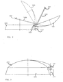
- FIG. 2 diagrammatically represents an antenna according to the invention, in various open positions. It comprises a receiving antenna 103 essentially parabolic or of equivalent form for the reception of audio-visual signals, articulated on a base 105 secured to a vehicle (not shown), such as the cabin of a truck for example, and a receiver 107 in his focus, mounted at the end of an arm 109.
- the parabola 103 rotates relative at the base 105 by means of a hinge with axis 111 (lifting movement) essentially in the upper plane of the base 105, arranged at the top lower part of the dish 103.
- the arm 109 carrying the receiver 107 is connected to the lower vertex of the parable 103, is retractable in the hollow of the parabola 103 when it is folded on its base 105 for a reduced bulk (see FIGS. 3 and 4), and is brought and maintained in position fixed in relation to the parable 103, namely in its home, when it is in open position of reception, using a linkage provided with a spring recall.
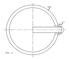
- the closed position of Figures 3 and 4 corresponds to the rest position.
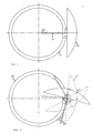
- Figure 5 shows the antenna in the open position; this may be the rest position with respect to azimuth.
- the hinge axis 111 is mounted on a perpendicular axis 113 which still allows a rotation of the parabola 103 with its receiver 107 around this axis 113, relative to the base 105, to allow rotation of azimuth.
- the FIG. 6 represents various receiving positions of the parabola 103 with its receiver 109.
- the rotation about the axis 111 can advantageously be controlled by a axial gear motor (9) housed in the hinge axis 111.
- the rotation around of the axis 113 is advantageously controlled by a drive group comprising motor and gearbox (7) housed in the hinge or in the base 105.
Landscapes
- Physics & Mathematics (AREA)
- Engineering & Computer Science (AREA)
- General Physics & Mathematics (AREA)
- Radar, Positioning & Navigation (AREA)
- Remote Sensing (AREA)
- Position Fixing By Use Of Radio Waves (AREA)
- Variable-Direction Aerials And Aerial Arrays (AREA)
Abstract
Description
- la figure 1 est une représentation schématique du dispositif d'orientation d'antenne selon l'invention;
- la figure 2 est une vue latérale d'une antenne selon l'invention;
- la figure 3 est une vue latérale de l'antenne en position de repos;
- la figure 4 est une vue du dessus de l'antenne de la figure 3 ;
- la figure 5 est une vue du dessus de l'antenne de l'invention, à l'état ouvert mais en position de repos en ce qui concerne l'azimut ; et
- la figure 6 est une vue en plan montrant diverses positions de l'antenne réception.
Claims (12)
- Dispositif d'orientation d'antenne comportant au moins un système de positionnement GPS (11) qui détermine les coordonnées de position de l'antenne (3) sur la terre, un moyen (13) qui détermine l'orientation de l'antenne (3) par rapport au nord magnétique, un moteur de positionnement de l'antenne pour ce qui concerne son azimut (7), un moteur de positionnement de l'antenne pour ce qui concerne son élévation (9), un interface utilisateur (15) pour le démarrage (17) dudit dispositif d'orientation d'antenne et le choix (19) d'un satellite géostationnaire (1) ainsi qu'un calculateur (21) qui pilote à l'aide de moyens connus en soi (23,25) les moteurs de positionnement (7,9) en fonction des informations reçues des divers capteurs (11,13,27,29) et du choix de satellite géostationnaire (1) afin de pointer ladite antenne (3) substantiellement sur ledit satellite (1).
- Dispositif selon la revendication 1 caractérisé en ce que le dispositif de l'invention comporte encore un détecteur de position (31) pour ce qui concerne l'azimut et un détecteur de position d'élévation (33).
- Dispositif selon la revendication 2 caractérisé en ce que les détecteurs (31,33) sont des détecteurs de position de repos.
- Dispositif selon l'une quelconque des revendications précédentes caractérisé en ce que le moteur de positionnement (7) de l'antenne (3) selon l'azimut déterminé par le calculateur (21) consiste avantageusement en un moteur permettant une rotation d'approximativement 360 degrés de l'antenne autour d'un axe normal à la plateforme mobile sur laquelle est montée l'antenne (3).
- Dispositif selon l'une quelconque des revendications précédentes caractérisé en ce que le moteur de positionnement (9) de l'antenne selon l'élévation déterminée par le calculateur (21) consiste avantageusement en un moteur permettant une rotation de 180 degrés à partir de la plateforme, autour d'un axe perpendiculaire à l'axe normale à ladite plateforme mobile.
- Dispositif selon l'une quelconque des revendications précédentes caractérisé en ce que le dispositif de l'invention peut encore comporter un détecteur de niveau (27,29) dans un axe (X) et dans un axe (Y) perpendiculaire à celui-ci.
- Dispositif selon l'une quelconque des revendications précédentes caractérisé en ce que le choix du satellite géostationnaire (1) est programmé d'avance.
- Dispositif selon l'une quelconque des revendications 1 à 6 caractérisé en ce que l'interface utilisateur (15) comporte un sélecteur (19) à multiples positions ou un ensemble de boutons poussoirs reliés par des moyens connus en soi au calculateur pour la transmission de l'information du choix du satellite géostationnaire voulu (1).
- Dispositif selon l'une quelconque des revendications 1 à 6 caractérisé en ce que l'interface utilisateur (15) consiste en un interface a écran permettant des choix multiples programmés.
- Dispositif selon l'une quelconque des revendications précédentes caractérisé en ce que l'une au moins des liaisons entre l'interface utilisateur (15) et le calculateur (21) ou entre le calculateur (21) et les commandes (23,25) des moteurs de positionnement (7,9) ou entre les divers capteurs ou détecteurs (11,13,27,29) et le calculateur (21) est une connexion sans fil.
- Procédé pour orienter une antenne de réception (3), notamment une antenne de réception montée sur une plateforme mobile, substantiellement sur un satellite géostationnaire (1), caractérisé par les étapes suivantes: (i) choix d'un satellite géostationnaire (1), (ii) localisation de l'antenne (3) par un systeme de positionnement du type GPS (11), (iii) détermination de l'orientation de ladite antenne (3) par rapport au nord magnétique, (iv) calcul de l'angle d'azimut et de l'angle d'élévation de l'antenne (3) en fonction des informations reçues du système GPS (11) et de divers capteurs (13,27,29), et (v) commande de moteurs de positionnement (7,9) de l'antenne (3) selon l'angle d'azimut calculé et selon l'angle d'élévation calculé.
- Procédé selon la revendication 11 caractérisé en ce qu'il comporte une étape de correction du calcul en fonction de données reçues de détecteurs de niveau (27,29) selon un certain axe et un axe perpendiculaire celui-ci.
Priority Applications (1)
| Application Number | Priority Date | Filing Date | Title |
|---|---|---|---|
| EP04447150A EP1610145A1 (fr) | 2004-06-22 | 2004-06-22 | Dispositif d'orientation d'antenne |
Applications Claiming Priority (1)
| Application Number | Priority Date | Filing Date | Title |
|---|---|---|---|
| EP04447150A EP1610145A1 (fr) | 2004-06-22 | 2004-06-22 | Dispositif d'orientation d'antenne |
Publications (1)
| Publication Number | Publication Date |
|---|---|
| EP1610145A1 true EP1610145A1 (fr) | 2005-12-28 |
Family
ID=34933054
Family Applications (1)
| Application Number | Title | Priority Date | Filing Date |
|---|---|---|---|
| EP04447150A Withdrawn EP1610145A1 (fr) | 2004-06-22 | 2004-06-22 | Dispositif d'orientation d'antenne |
Country Status (1)
| Country | Link |
|---|---|
| EP (1) | EP1610145A1 (fr) |
Cited By (8)
| Publication number | Priority date | Publication date | Assignee | Title |
|---|---|---|---|---|
| WO2008106624A3 (fr) * | 2007-02-28 | 2008-10-16 | Slacker Inc | Antenne réseau pour un motif de faisceau d'antenne haut/bas et procédé d'utilisation |
| WO2008127750A3 (fr) * | 2007-01-22 | 2008-12-04 | Raytheon Co | Procédé et système de contrôle de la direction d'un faisceau d'antenne |
| US9026161B2 (en) | 2012-04-19 | 2015-05-05 | Raytheon Company | Phased array antenna having assignment based control and related techniques |
| US20160335258A1 (en) | 2006-10-24 | 2016-11-17 | Slacker, Inc. | Methods and systems for personalized rendering of digital media content |
| FR3064823A1 (fr) * | 2017-03-30 | 2018-10-05 | Neo Technologies | Systeme de pointage vers une source radio fixe dote d'un moyen d'orientation automatique vers cette source. |
| US10275463B2 (en) | 2013-03-15 | 2019-04-30 | Slacker, Inc. | System and method for scoring and ranking digital content based on activity of network users |
| US10313754B2 (en) | 2007-03-08 | 2019-06-04 | Slacker, Inc | System and method for personalizing playback content through interaction with a playback device |
| CN114895721A (zh) * | 2022-05-18 | 2022-08-12 | 中国船舶集团有限公司第七二三研究所 | 一种大型方位转台快速定向置位回收控制方法 |
Citations (5)
| Publication number | Priority date | Publication date | Assignee | Title |
|---|---|---|---|---|
| US5347286A (en) * | 1992-02-13 | 1994-09-13 | Trimble Navigation Limited | Automatic antenna pointing system based on global positioning system (GPS) attitude information |
| US6016120A (en) * | 1998-12-17 | 2000-01-18 | Trimble Navigation Limited | Method and apparatus for automatically aiming an antenna to a distant location |
| US6023242A (en) * | 1998-07-07 | 2000-02-08 | Northern Telecom Limited | Establishing communication with a satellite |
| US6049306A (en) * | 1996-01-04 | 2000-04-11 | Amarillas; Sal | Satellite antenna aiming device featuring real time elevation and heading adjustment |
| US6487426B1 (en) * | 1999-12-16 | 2002-11-26 | Motorola | Self-aligning wireless interface system and method |
-
2004
- 2004-06-22 EP EP04447150A patent/EP1610145A1/fr not_active Withdrawn
Patent Citations (5)
| Publication number | Priority date | Publication date | Assignee | Title |
|---|---|---|---|---|
| US5347286A (en) * | 1992-02-13 | 1994-09-13 | Trimble Navigation Limited | Automatic antenna pointing system based on global positioning system (GPS) attitude information |
| US6049306A (en) * | 1996-01-04 | 2000-04-11 | Amarillas; Sal | Satellite antenna aiming device featuring real time elevation and heading adjustment |
| US6023242A (en) * | 1998-07-07 | 2000-02-08 | Northern Telecom Limited | Establishing communication with a satellite |
| US6016120A (en) * | 1998-12-17 | 2000-01-18 | Trimble Navigation Limited | Method and apparatus for automatically aiming an antenna to a distant location |
| US6487426B1 (en) * | 1999-12-16 | 2002-11-26 | Motorola | Self-aligning wireless interface system and method |
Cited By (10)
| Publication number | Priority date | Publication date | Assignee | Title |
|---|---|---|---|---|
| US20160335258A1 (en) | 2006-10-24 | 2016-11-17 | Slacker, Inc. | Methods and systems for personalized rendering of digital media content |
| US10657168B2 (en) | 2006-10-24 | 2020-05-19 | Slacker, Inc. | Methods and systems for personalized rendering of digital media content |
| WO2008127750A3 (fr) * | 2007-01-22 | 2008-12-04 | Raytheon Co | Procédé et système de contrôle de la direction d'un faisceau d'antenne |
| US7898476B2 (en) | 2007-01-22 | 2011-03-01 | Raytheon Company | Method and system for controlling the direction of an antenna beam |
| WO2008106624A3 (fr) * | 2007-02-28 | 2008-10-16 | Slacker Inc | Antenne réseau pour un motif de faisceau d'antenne haut/bas et procédé d'utilisation |
| US10313754B2 (en) | 2007-03-08 | 2019-06-04 | Slacker, Inc | System and method for personalizing playback content through interaction with a playback device |
| US9026161B2 (en) | 2012-04-19 | 2015-05-05 | Raytheon Company | Phased array antenna having assignment based control and related techniques |
| US10275463B2 (en) | 2013-03-15 | 2019-04-30 | Slacker, Inc. | System and method for scoring and ranking digital content based on activity of network users |
| FR3064823A1 (fr) * | 2017-03-30 | 2018-10-05 | Neo Technologies | Systeme de pointage vers une source radio fixe dote d'un moyen d'orientation automatique vers cette source. |
| CN114895721A (zh) * | 2022-05-18 | 2022-08-12 | 中国船舶集团有限公司第七二三研究所 | 一种大型方位转台快速定向置位回收控制方法 |
Similar Documents
| Publication | Publication Date | Title |
|---|---|---|
| EP3210660B1 (fr) | Drone avec bras de liaison pliables | |
| EP1610145A1 (fr) | Dispositif d'orientation d'antenne | |
| FR3079094A1 (fr) | Dispositif de commande a distance, par exemple pour commander un drone a distance | |
| FR3048186A1 (fr) | Drone ayant des supports de drone relevables | |
| FR2861657A1 (fr) | Poste de conduite d'un vehicule automobile | |
| CA2255118C (fr) | Appareil individuel d'orientation | |
| FR2696384A1 (fr) | Dispositif pour la commande de réglage d'un siège de véhicule. | |
| EP0171318B1 (fr) | Dispositif de réglage de la position de projecteurs de véhicules | |
| EP4408786B1 (fr) | Engin de manutention | |
| WO2019106300A1 (fr) | Procédé d'activation d'au moins une fonction d'un équipement d'un véhicule | |
| FR3043789A1 (fr) | Chargement de donnees d'ephemerides dans un drone. | |
| FR2987584A1 (fr) | Vehicule automobile equipe d'un support d'appareil electronique nomade | |
| WO2017153307A1 (fr) | Équipement électronique d'aide au stationnement pour véhicule automobile | |
| FR3064823A1 (fr) | Systeme de pointage vers une source radio fixe dote d'un moyen d'orientation automatique vers cette source. | |
| FR3140327A1 (fr) | Dispositif d’accueil pour appareil nomade dans un équipement pourvu d’une façade de style | |
| EP1320145A1 (fr) | Procédé et dispositif de pointage d'antenne | |
| FR3115226A1 (fr) | Procédé et ensemble de robots mobiles autonomes pour l’exploration d’un lieu | |
| WO2004041569A1 (fr) | Toit retractable pour vehicule automobile | |
| US20200070923A1 (en) | Self-balancing base with carriage | |
| FR2768282A1 (fr) | Systeme portable d'appel urgent pour radio-mobile comprenant un systeme de reperage par satellites avec un dispositif d'orientation automatique de son antenne, un dispositif de mesure de l'acceleration et un photogenerateur | |
| FR3071455A1 (fr) | Station d'accueil pour appareil electronique nomade et element de garnissage de vehicule comprenant une telle station d'accueil | |
| BE1024603B1 (fr) | Ensemble d'une planche à roulette à moteur et du dispositif de commande du moteur | |
| FR2915332A1 (fr) | Adaptateur telephonique autonome de type "mains libres" enfichable dans la prise allume-cigare d'un vehicule automobile | |
| EP2681073A1 (fr) | Dispositif de repose-mollets escamotable, en particulier pour vehicules automobiles | |
| EP4116796A1 (fr) | Dispositif de commande d'une ou plusieurs fonction(s) de travail d'une machine agricole et machine agricole munie dudit dispositif de commande |
Legal Events
| Date | Code | Title | Description |
|---|---|---|---|
| PUAI | Public reference made under article 153(3) epc to a published international application that has entered the european phase |
Free format text: ORIGINAL CODE: 0009012 |
|
| AK | Designated contracting states |
Kind code of ref document: A1 Designated state(s): AT BE BG CH CY CZ DE DK EE ES FI FR GB GR HU IE IT LI LU MC NL PL PT RO SE SI SK TR |
|
| AX | Request for extension of the european patent |
Extension state: AL HR LT LV MK |
|
| AKX | Designation fees paid | ||
| REG | Reference to a national code |
Ref country code: DE Ref legal event code: 8566 |
|
| RAP1 | Party data changed (applicant data changed or rights of an application transferred) |
Owner name: STRAETMANS, HENRI Owner name: DOUTREPONT, GEORGES |
|
| RIN1 | Information on inventor provided before grant (corrected) |
Inventor name: STRAETMANS, HENRI Inventor name: DOUTREPONT, GEORGES |
|
| STAA | Information on the status of an ep patent application or granted ep patent |
Free format text: STATUS: THE APPLICATION IS DEEMED TO BE WITHDRAWN |
|
| 18D | Application deemed to be withdrawn |
Effective date: 20060629 |