EP1610285A1 - Dispositif pour arranger au moins une fibre optique ou un paquet de fibres optiques pour former une image lumineuse ou une information lumineuse ainsi que procédé de réalisation d'images lumineuses ou d'informations lumineuses - Google Patents
Dispositif pour arranger au moins une fibre optique ou un paquet de fibres optiques pour former une image lumineuse ou une information lumineuse ainsi que procédé de réalisation d'images lumineuses ou d'informations lumineuses Download PDFInfo
- Publication number
- EP1610285A1 EP1610285A1 EP04013845A EP04013845A EP1610285A1 EP 1610285 A1 EP1610285 A1 EP 1610285A1 EP 04013845 A EP04013845 A EP 04013845A EP 04013845 A EP04013845 A EP 04013845A EP 1610285 A1 EP1610285 A1 EP 1610285A1
- Authority
- EP
- European Patent Office
- Prior art keywords
- carrier plate
- optical waveguide
- light
- cover
- optical
- Prior art date
- Legal status (The legal status is an assumption and is not a legal conclusion. Google has not performed a legal analysis and makes no representation as to the accuracy of the status listed.)
- Withdrawn
Links
- 230000003287 optical effect Effects 0.000 title claims description 38
- 238000004519 manufacturing process Methods 0.000 title claims description 8
- 238000000034 method Methods 0.000 title claims description 8
- 239000000463 material Substances 0.000 claims description 51
- 239000013307 optical fiber Substances 0.000 claims description 26
- 239000010426 asphalt Substances 0.000 claims description 15
- 230000008878 coupling Effects 0.000 claims description 9
- 238000010168 coupling process Methods 0.000 claims description 9
- 238000005859 coupling reaction Methods 0.000 claims description 9
- 238000006243 chemical reaction Methods 0.000 claims description 8
- 239000004033 plastic Substances 0.000 claims description 6
- 239000011521 glass Substances 0.000 claims description 4
- 229910000831 Steel Inorganic materials 0.000 claims description 3
- 230000001681 protective effect Effects 0.000 claims description 3
- 239000010959 steel Substances 0.000 claims description 3
- 230000009182 swimming Effects 0.000 claims description 3
- 239000002023 wood Substances 0.000 claims description 3
- 239000011505 plaster Substances 0.000 claims description 2
- 239000004417 polycarbonate Substances 0.000 claims description 2
- 229920000515 polycarbonate Polymers 0.000 claims description 2
- 239000000835 fiber Substances 0.000 description 14
- 229910001220 stainless steel Inorganic materials 0.000 description 4
- 239000010935 stainless steel Substances 0.000 description 4
- 239000004575 stone Substances 0.000 description 3
- XLYOFNOQVPJJNP-UHFFFAOYSA-N water Substances O XLYOFNOQVPJJNP-UHFFFAOYSA-N 0.000 description 3
- 238000005253 cladding Methods 0.000 description 1
- 238000010276 construction Methods 0.000 description 1
- 238000005553 drilling Methods 0.000 description 1
- 230000008014 freezing Effects 0.000 description 1
- 238000007710 freezing Methods 0.000 description 1
- 238000009434 installation Methods 0.000 description 1
- 230000010354 integration Effects 0.000 description 1
- 239000004922 lacquer Substances 0.000 description 1
- 239000003973 paint Substances 0.000 description 1
- 230000005855 radiation Effects 0.000 description 1
- 239000007787 solid Substances 0.000 description 1
- 125000006850 spacer group Chemical group 0.000 description 1
- 230000003068 static effect Effects 0.000 description 1
Images

Classifications
-
- G—PHYSICS
- G09—EDUCATION; CRYPTOGRAPHY; DISPLAY; ADVERTISING; SEALS
- G09F—DISPLAYING; ADVERTISING; SIGNS; LABELS OR NAME-PLATES; SEALS
- G09F9/00—Indicating arrangements for variable information in which the information is built-up on a support by selection or combination of individual elements
- G09F9/30—Indicating arrangements for variable information in which the information is built-up on a support by selection or combination of individual elements in which the desired character or characters are formed by combining individual elements
- G09F9/305—Indicating arrangements for variable information in which the information is built-up on a support by selection or combination of individual elements in which the desired character or characters are formed by combining individual elements being the ends of optical fibres
Definitions
- the invention relates to a device for arrangement at least one optical waveguide or optical fiber bundle to a photograph or a light information as well a process for the production of photographs or Light information.
- the invention underlying technical problem
- a device for arranging a plurality of optical waveguides or fiber optic bundles specify in which the optical fibers or fiber optic bundles easy to position, and the above also versatile.
- the device according to the invention has at least one Support plate, wherein in and / or on the support plate Holder for ends of optical fibers or fiber optic bundles are arranged.
- the holders for the ends of the Optical waveguides or optical waveguide bundles become such arranged that a photograph, for example a Lettering or other light information shown becomes.
- the device according to the invention is in traffic areas of all kinds, that is to be walked in and out of people of passenger cars, bicycles, trucks and Aircraft traversable areas outdoors as well as in Halls and buildings can be used.
- the device suitable for wall or ceiling mounting. It It is also possible to use ice rinks or swimming pools.
- a backfill material can be arranged.
- the holders for the optical waveguides are advantageous height adjustable and adjustable on or in the carrier plate arranged. This makes it advantageous according to this Embodiment possible, all holders and thus all Ends the optical fibers at exactly one height adjust.
- This embodiment is particularly advantageous if the carrier plate with the backfill material, for example a pourable material, is filled, so that All ends of the optical fiber flush with the surface complete or at least the same distance from the surface are arranged.
- the holders are tubular to the ends of the Receive optical fiber.
- the holders can a or a plurality of optical waveguides can be arranged.
- the Cover is advantageously formed translucent.
- the cover thus represents a diffuser, so that the light is scattered diffusely.
- This cover is required when the holders are arranged vertically on the carrier plate are, so that the light is scattered and thus, for example Motorists can recognize the lettering out of the car. Without the diffuse scattering of light, the light information would be not or only partially recognizable.
- the cover may instead of training as a diffuser also as an optical element, for example as a lens, Prism or mirror or the like may be designed to to change the beam path.
- the cover can be in this Case in polished, matt or translucent design be designed. It is also possible to do a simple Provide protective glass, for example, when the inventive Device intended for wall or ceiling mounting is.
- the support plate is advantageously made of steel, plastic and / or wood formed.
- In the drive-over area is preferably steel or stainless steel are used to the to reach necessary carrying capacity.
- In only accessible Areas may be the support plate made of plastic or Be formed wood. The same applies in the event that the Support plate arranged on a wall or a ceiling becomes.
- the support plate In the outdoor area, the support plate should be weather-resistant be educated.
- the carrier plate with a simple Base area, such as a rectangle, a circle, a square or the like configured.
- the base of the carrier plate is then independent of the arrangement of the optical waveguide designed.
- the carrier plate to the arrangement of the optical waveguide adapted to train.
- This embodiment is advantageous for example in the arrangement of the optical waveguide in the form of a letter.
- the carrier plate may in this case also have the shape of the letter.
- the device according to the invention with the carrier plate has the advantage that, especially in a series production the carrier plate in a simple manner with predetermined Holes can be produced. In the holes are turn the holder used, in which then the Fiber optic cables are arranged. Subsequently, the Support plate with a backfill material, such as a pourable material are filled, depending on the application form.
- photographs can be in, for example, in Making lettering very simple and inexpensive.
- the backfill material is advantageous as a reactive curing Material formed.
- the material hardens in this Case cold.
- the temperature of the backfill material during curing does not exceed 80 ° C, so that the optical fibers with their cladding take no damage.
- reaction asphalt is in the Austrian Patent No. AT 406,375.
- the backfill material is advantageous weather resistant trained.
- optical waveguides are conventional optical waveguides, For example, made of glass or plastic, used.
- the photo is also possible to have one or more area lights on or in to arrange the carrier plate.
- area lights for example so-called light stones are used.
- the light stones are lamps that also be illuminated via optical fibers, and in which provided a large-scale coverage for scattering the light is.
- the area lights can have any shape.
- the device advantageously has a carrier plate on, which is designed as a perforated plate.
- a carrier plate on which is designed as a perforated plate.
- the backfill material is poured so that the backfill material in one of the perforated plate and on the carrier plate arranged frame limited space can be placed can.
- the optical fibers are arranged, advantageous with a light connector or a coupling. The light connector or the light coupling remains exposed, leaving a projector or a via a clutch connected further optical fiber connectable is.
- This embodiment has the advantage that the optical waveguides are protected by the filling material, and although especially against moisture and mechanical Print.
- a subframe is attached, the form-fitting accommodates the support plate.
- the perforated plate of the carrier plate arranged space can thus further backfill material are introduced, which are the holders of the optical waveguide encloses.
- a Cover layer (asphalt cover layer) applied.
- a finish layer for example, a finish layer, and the covers will be in the finish layer arranged. These can be glued in there. It is also possible in the finish layer on the holders nuts provide, in which the covers are screwed.
- the Finish layer can vary as required Have surface textures and colored decor.
- the carrier plate instead of the backfill material, the carrier plate to be provided with a stainless steel plate as a cover.
- the Cover plate closes flush with the holders of the optical fibers from.
- the cover plate can not only be used as a stainless steel plate but also made of other materials be. It can be provided mounting plates, for example Heraclite plates that can be overpainted.
- the device according to the invention can moreover be used in the swimming pool area. Especially in concrete pools can cast the carrier plate according to the invention become.
- the device according to the invention in ice surfaces, for example to arrange an ice rink.
- the lower part of the carrier plate, in which the optical waveguides are arranged can be poured out to protect the optical fibers to reach the water.
- the Carrier plate for example, arranged on a first layer of ice become. Water is placed on the first layer of ice which completely completes the device according to the invention encloses. Subsequently, the water is freezing exposed and the device of the invention fixed in the ice.
- the optical fiber in this one holder for example, part of a Be running light.
- the carrier plate relatively small.
- the support plate is preferably flat. It However, other versions are possible.
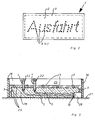
- Fig. 1 shows a device (1) with a carrier plate (2) having a frame (3).
- the carrier plate (2) are holders (4) for ends of optical fibers (5) arranged.
- the holders (4) have an external thread and are arranged in bores (6) of the carrier plate (2), wherein the bores (6) have an internal thread (7).
- the holder (4) in the support plate arranged height adjustable.
- a filling material (19) for example a base course material arranged. It is possible the cavity (25) with concrete, reaction asphalt or other filling material pour out.
- the support layer (19) and the carrier plate (2) form a static unit. simultaneously are the optical fibers (5) and a coupling (28) in the device (1) fixed and against moisture and mechanical Pressure protected.
- the carrier plate (2) is another layer preferably arranged from reaction asphalt (8).
- reaction asphalt (8) By This reaction asphalt (8), the holder (4) are fixed.
- the holders (4) have covers (9) which serve as Diffuser are formed.
- the covers (9) consist of a translucent material.
- the optical waveguides (5) are via the coupling (28) on a projector (11) via a light fiber bundle (29), which with a plug (10) connected to the projector (11) is connected.
- the coupling (28) is in a cutout (30) of the Frame (3) arranged accessible from the outside.
- the carrier plate (2) is a perforated plate with holes (23) formed. Through these holes (23) is the support layer material (19), as will be explained in Fig. 3, in potted the cavity (25).
- the reaction asphalt (8) has a cover layer (20) on, which represents the finish, that is, the one aesthetically appealing surface forms.
- the holder (4) in the Device (1) arranged such that it is a lettering result. If this lettering, for example, in a Road arranged so motorists can use this lettering recognize and read in the dark.
- Fig. 3 shows the carrier plate (2) with the holes (23).
- the holder (4) are arranged, which in turn carry nuts (22).
- the covers (9) (not shown in Fig. 3) arranged.
- Fig. 3 shows the carrier plate (2) with the with Supporting layer material (19) poured cavity (25).
- Supporting layer material (19) are the optical waveguides (5) and arranged the plug (10).
- the base course material (19) is through the holes (23) formed as a perforated plate Cast support plate (2).
- pouring is the carrier plate arranged on a support surface (21).
- a subframe (18) surrounds the carrier plate (2) positively, so that a cavity (26) also with a Filling material, for example, with that shown in Fig. 1 Reaction asphalt (8), can be poured out.
- the method step 4 is optional.
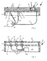
- Fig. 4 shows the device (1) with the carrier plate (2) and the frame (3).
- a holder (4) like him already shown in Fig. 1, is another holder (12) arranged in the carrier plate (2).
- This holder (12) is angled to a vertical of the support plate (2) arranged.
- the holder (12) has no cover, so that the light is emitted vertically. It takes place in In this case, no diffuse radiation.
- a surface light (13) arranged in the form of a so-called light stone.
- the area light (13) consists of a cuboid Body (14) coated inside with a white lacquer (15) is.
- the surface light (13) carries a cover (16), which in turn is designed as a diffuser.
- the optical fiber (5) is introduced laterally into the surface light (13), allowing a uniform emission of light through the translucent cover (16).
- the layer over the carrier plate (2) is made of a multilayer reactive curing material (17).
- Fig. 5 shows a further embodiment of the device (1).
- the support plate (2) is not in this case as a perforated plate, but formed as a solid sheet.
- holder (4) for the optical waveguide (5) arranged.
- As a cover is a stainless steel plate (24) provided by the holder (4) by in the cover plate (24) arranged bores (27) are.
- the covers (9) are in the present case as Formed prisms, that is as optical elements.
- the Optical waveguide (5) and a coupling (28) are in the Cavity (25) arranged.
- about the clutch (28) is a Bundle of further optical fibers connectable to a Projector (not shown in Fig. 5) are guided.
- the cover plate (24) is with spacers (31) on the support plate (2) attached.
Landscapes
- Physics & Mathematics (AREA)
- General Physics & Mathematics (AREA)
- Engineering & Computer Science (AREA)
- Theoretical Computer Science (AREA)
- Light Guides In General And Applications Therefor (AREA)
Priority Applications (1)
| Application Number | Priority Date | Filing Date | Title |
|---|---|---|---|
| EP04013845A EP1610285A1 (fr) | 2004-06-14 | 2004-06-14 | Dispositif pour arranger au moins une fibre optique ou un paquet de fibres optiques pour former une image lumineuse ou une information lumineuse ainsi que procédé de réalisation d'images lumineuses ou d'informations lumineuses |
Applications Claiming Priority (1)
| Application Number | Priority Date | Filing Date | Title |
|---|---|---|---|
| EP04013845A EP1610285A1 (fr) | 2004-06-14 | 2004-06-14 | Dispositif pour arranger au moins une fibre optique ou un paquet de fibres optiques pour former une image lumineuse ou une information lumineuse ainsi que procédé de réalisation d'images lumineuses ou d'informations lumineuses |
Publications (1)
| Publication Number | Publication Date |
|---|---|
| EP1610285A1 true EP1610285A1 (fr) | 2005-12-28 |
Family
ID=34925341
Family Applications (1)
| Application Number | Title | Priority Date | Filing Date |
|---|---|---|---|
| EP04013845A Withdrawn EP1610285A1 (fr) | 2004-06-14 | 2004-06-14 | Dispositif pour arranger au moins une fibre optique ou un paquet de fibres optiques pour former une image lumineuse ou une information lumineuse ainsi que procédé de réalisation d'images lumineuses ou d'informations lumineuses |
Country Status (1)
| Country | Link |
|---|---|
| EP (1) | EP1610285A1 (fr) |
Citations (5)
| Publication number | Priority date | Publication date | Assignee | Title |
|---|---|---|---|---|
| DE3500123A1 (de) * | 1985-01-04 | 1986-07-10 | Faseroptik Henning & Gettwart GmbH, 8501 Allersberg | Signalanzeigevorrichtung zur ausstrahlung von lichtzeichen |
| EP0348619A2 (fr) * | 1988-06-30 | 1990-01-03 | Schölly Fiberoptic Gmbh | Signalisation changeable |
| US5651924A (en) * | 1990-11-09 | 1997-07-29 | Tchai Lights B.V. | Method for manufacturing light panels |
| US6078439A (en) * | 1998-01-19 | 2000-06-20 | Swarco Futurit Verkehrssignalsysteme Ges.Mbh | Optics unit for signal, traffic and display equipment, arrangement of the same therein and method therefore |
| US6305874B1 (en) * | 1999-05-20 | 2001-10-23 | U.S. Philips Corporation | Road-marking complex and system for marking roads |
-
2004
- 2004-06-14 EP EP04013845A patent/EP1610285A1/fr not_active Withdrawn
Patent Citations (5)
| Publication number | Priority date | Publication date | Assignee | Title |
|---|---|---|---|---|
| DE3500123A1 (de) * | 1985-01-04 | 1986-07-10 | Faseroptik Henning & Gettwart GmbH, 8501 Allersberg | Signalanzeigevorrichtung zur ausstrahlung von lichtzeichen |
| EP0348619A2 (fr) * | 1988-06-30 | 1990-01-03 | Schölly Fiberoptic Gmbh | Signalisation changeable |
| US5651924A (en) * | 1990-11-09 | 1997-07-29 | Tchai Lights B.V. | Method for manufacturing light panels |
| US6078439A (en) * | 1998-01-19 | 2000-06-20 | Swarco Futurit Verkehrssignalsysteme Ges.Mbh | Optics unit for signal, traffic and display equipment, arrangement of the same therein and method therefore |
| US6305874B1 (en) * | 1999-05-20 | 2001-10-23 | U.S. Philips Corporation | Road-marking complex and system for marking roads |
Similar Documents
| Publication | Publication Date | Title |
|---|---|---|
| DE69227387T2 (de) | Notausganganzeigesystem | |
| DE4236799A1 (de) | Verfahren zur Herstellung von Tripel-Reflektoren und deren Werkzeugen | |
| WO2000039501A1 (fr) | Source lumineuse a couplage lateral oblique de lumiere | |
| DE102008055857B4 (de) | Effiziente Lichtumlenkvorrichtung mit zweiseitiger prismatischer und linsenartiger Oberflächenstrukturierung | |
| DE69306669T2 (de) | Lichtstreuender Glasbaustein | |
| DE102007059561A1 (de) | Leuchtende Glaswand | |
| DE19936982A1 (de) | Innenausbauteil für Kraftfahrzeuge | |
| EP1610285A1 (fr) | Dispositif pour arranger au moins une fibre optique ou un paquet de fibres optiques pour former une image lumineuse ou une information lumineuse ainsi que procédé de réalisation d'images lumineuses ou d'informations lumineuses | |
| DE102011114126A1 (de) | Verfahren und Vorrichtung zum Herstellen eines Formkörpers mit Lichtleitern sowie Formkörper aus einer härtbaren oder aushärtenden gießfähigen Masse | |
| DE10313353A1 (de) | Funkwellenreflektor und Struktur, an der der Funkwellenreflektor befestigt ist | |
| DE4301118C2 (de) | Naturstein-Fertigbauteil | |
| DE4332458C1 (de) | Dekortafel | |
| DE3721115A1 (de) | Traeger von strassenverkehrszeichen, richtungsweisern, fussgaengerschutzzaeunen und aehnlichem | |
| WO2011038717A1 (fr) | Dalles de pierre de taille à liant polymère ou cimentaire partiellement transparentes | |
| DE102019105092B4 (de) | Optimiertes Linsendesign für die Lichtumlenkung | |
| EP1637656B1 (fr) | Dispositif avec des diodes électroluminescentes pour le marquage des surfaces | |
| DE19731142A1 (de) | Lichtverteilstruktur | |
| DE10214761B4 (de) | Verkleidungselement für Gebäude, insbesondere Decken | |
| DE3003426A1 (de) | Beschilderungsbaukasten | |
| DE102009043662B4 (de) | Partiell lichtdurchlässige zementös oder polymer gebundene Werksteinplatten | |
| DE2718352C2 (de) | Leitpfosten für Fahrbahnen | |
| DE8913272U1 (de) | Bausatz zur Ausbildung von Leitwegen | |
| DE4112702A1 (de) | Reflektierender strassenmarkierungsknopf | |
| DE3006830C2 (fr) | ||
| DE202009013134U1 (de) | Partiell lichtdurchlässige zementös oder polymer gebundene Werksteinplatten |
Legal Events
| Date | Code | Title | Description |
|---|---|---|---|
| PUAI | Public reference made under article 153(3) epc to a published international application that has entered the european phase |
Free format text: ORIGINAL CODE: 0009012 |
|
| AK | Designated contracting states |
Kind code of ref document: A1 Designated state(s): AT BE BG CH CY CZ DE DK EE ES FI FR GB GR HU IE IT LI LU MC NL PL PT RO SE SI SK TR |
|
| AX | Request for extension of the european patent |
Extension state: AL HR LT LV MK |
|
| AKX | Designation fees paid | ||
| 19U | Interruption of proceedings before grant |
Effective date: 20050929 |
|
| REG | Reference to a national code |
Ref country code: DE Ref legal event code: 8566 |
|
| 19W | Proceedings resumed before grant after interruption of proceedings |
Effective date: 20081001 |
|
| STAA | Information on the status of an ep patent application or granted ep patent |
Free format text: STATUS: THE APPLICATION HAS BEEN WITHDRAWN |
|
| 18W | Application withdrawn |
Effective date: 20080627 |