EP1610485A2 - Dispositif, système et procédé de détection d'erreurs des données in vivo - Google Patents
Dispositif, système et procédé de détection d'erreurs des données in vivo Download PDFInfo
- Publication number
- EP1610485A2 EP1610485A2 EP05105580A EP05105580A EP1610485A2 EP 1610485 A2 EP1610485 A2 EP 1610485A2 EP 05105580 A EP05105580 A EP 05105580A EP 05105580 A EP05105580 A EP 05105580A EP 1610485 A2 EP1610485 A2 EP 1610485A2
- Authority
- EP
- European Patent Office
- Prior art keywords
- data
- error correction
- image data
- vivo
- block
- Prior art date
- Legal status (The legal status is an assumption and is not a legal conclusion. Google has not performed a legal analysis and makes no representation as to the accuracy of the status listed.)
- Withdrawn
Links
Images

Classifications
-
- H—ELECTRICITY
- H04—ELECTRIC COMMUNICATION TECHNIQUE
- H04L—TRANSMISSION OF DIGITAL INFORMATION, e.g. TELEGRAPHIC COMMUNICATION
- H04L1/00—Arrangements for detecting or preventing errors in the information received
- H04L1/004—Arrangements for detecting or preventing errors in the information received by using forward error control
- H04L1/0045—Arrangements at the receiver end
-
- A—HUMAN NECESSITIES
- A61—MEDICAL OR VETERINARY SCIENCE; HYGIENE
- A61B—DIAGNOSIS; SURGERY; IDENTIFICATION
- A61B1/00—Instruments for performing medical examinations of the interior of cavities or tubes of the body by visual or photographical inspection, e.g. endoscopes; Illuminating arrangements therefor
- A61B1/00002—Operational features of endoscopes
- A61B1/00011—Operational features of endoscopes characterised by signal transmission
- A61B1/00016—Operational features of endoscopes characterised by signal transmission using wireless means
-
- A—HUMAN NECESSITIES
- A61—MEDICAL OR VETERINARY SCIENCE; HYGIENE
- A61B—DIAGNOSIS; SURGERY; IDENTIFICATION
- A61B1/00—Instruments for performing medical examinations of the interior of cavities or tubes of the body by visual or photographical inspection, e.g. endoscopes; Illuminating arrangements therefor
- A61B1/04—Instruments for performing medical examinations of the interior of cavities or tubes of the body by visual or photographical inspection, e.g. endoscopes; Illuminating arrangements therefor combined with photographic or television appliances
- A61B1/041—Capsule endoscopes for imaging
-
- A—HUMAN NECESSITIES
- A61—MEDICAL OR VETERINARY SCIENCE; HYGIENE
- A61B—DIAGNOSIS; SURGERY; IDENTIFICATION
- A61B5/00—Measuring for diagnostic purposes; Identification of persons
- A61B5/07—Endoradiosondes
- A61B5/073—Intestinal transmitters
-
- A—HUMAN NECESSITIES
- A61—MEDICAL OR VETERINARY SCIENCE; HYGIENE
- A61B—DIAGNOSIS; SURGERY; IDENTIFICATION
- A61B5/00—Measuring for diagnostic purposes; Identification of persons
- A61B5/145—Measuring characteristics of blood in vivo, e.g. gas concentration or pH-value ; Measuring characteristics of body fluids or tissues, e.g. interstitial fluid or cerebral tissue
- A61B5/14539—Measuring characteristics of blood in vivo, e.g. gas concentration or pH-value ; Measuring characteristics of body fluids or tissues, e.g. interstitial fluid or cerebral tissue for measuring pH
-
- H—ELECTRICITY
- H04—ELECTRIC COMMUNICATION TECHNIQUE
- H04L—TRANSMISSION OF DIGITAL INFORMATION, e.g. TELEGRAPHIC COMMUNICATION
- H04L1/00—Arrangements for detecting or preventing errors in the information received
- H04L1/004—Arrangements for detecting or preventing errors in the information received by using forward error control
- H04L1/0041—Arrangements at the transmitter end
-
- H—ELECTRICITY
- H04—ELECTRIC COMMUNICATION TECHNIQUE
- H04L—TRANSMISSION OF DIGITAL INFORMATION, e.g. TELEGRAPHIC COMMUNICATION
- H04L1/00—Arrangements for detecting or preventing errors in the information received
- H04L1/004—Arrangements for detecting or preventing errors in the information received by using forward error control
- H04L1/0056—Systems characterized by the type of code used
- H04L1/0057—Block codes
-
- H—ELECTRICITY
- H04—ELECTRIC COMMUNICATION TECHNIQUE
- H04L—TRANSMISSION OF DIGITAL INFORMATION, e.g. TELEGRAPHIC COMMUNICATION
- H04L1/00—Arrangements for detecting or preventing errors in the information received
- H04L1/0001—Systems modifying transmission characteristics according to link quality, e.g. power backoff
Definitions
- the present invention relates to a device, system and method of error detection and/or correction of transmitted data that may be collected in-vivo.
- Transmission of data such as digital data over, for example, wireless media may result in the corruption of segments or portions of such data between the point of transmission of such data and the point of reception of such data.
- the transmission of digitized video or image data over a wireless system may result in incomplete or otherwise corrupted bytes or other data units that make up the digitized video.
- Error correction coding techniques may detect and possibly correct errors that occur in such transmissions.
- one or more symbols, bytes or other units of data may be added to a stream of data being transmitted.
- the value of the encoded data units may be used as a check on, for example, the content of bits or bytes of information that were transmitted, or on another aspect of the data being transmitted,
- a receiver may decode the encoded data and check the received data stream against the encoded values to ensure, for example, that the transmitted data was received correctly. In some error events detected errors may be corrected. Other methods or techniques of error detection and/or correction are possible.
- a device, system and method for including error correction coding techniques such as block coding or such as, for example, those based on Bose Chaudhuri Hocquenghem (BCH) coding schemes, in digitized data transmitted by an in-vivo sensing device such as, for example, an autonomous imaging capsule to an external receiver.
- Error correction codes may be included or encoded into the data that is produced and transmitted by, for example, an in-vivo sensing device.
- the encoded data may be received and decoded by, for example, a decoder associated with a receiver of the digitized data.
- the receiver may include a mechanism that may decode the transmitted data. Corrupted data may in some cases be partially or fully corrected, retransmitted or otherwise accounted for.
- error correction or "error correcting” may be interpreted to include error detection and/or correction.
- correction decoder may be interpreted to include an "error detector”.
- embodiments of the present invention may be directed to an autonomous, typically swallowable in-vivo device. Other embodiments need not be swallowable.
- Devices or systems according to embodiments of the present invention may be similar to embodiments described in International Application WO 01/65995 and/or in U.S. Patent No. 5,604,531, each of which are assigned to the common assignee of the present invention and each of which are hereby fully incorporated by reference.
- a receiving and/or display system suitable for use with embodiments of the present invention may also be similar to embodiments described in WO 01/65995 and/or in U.S. Patent Number 5,604,531.
- Devices and systems as described herein may have other configurations and other sets of components.
- Alternate embodiments of a device, system and method according to various embodiments of the invention may be used with other devices, non-imaging and/or non-in-vivo devices.
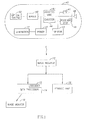
- the system may include a device 40 having a sensor such as, for example, an imager 46, an illumination source 42, and a transmitter 41.
- the device 40 may include a receiver unit 49.
- device 40 may be implemented using a swallowable capsule, but other sorts of devices or suitable implementations may be used.
- other sensors 43 in addition to or instead of imager 46 such as, for example, pH, temperature, pressure or other physiological parameter sensors may be included in device 40.
- Transmitter 41 may operate using radio waves, but in some embodiments, other wireless transmission media may be used.
- Device 40 may include a processing unit 47 that may, for example, contain or process instructions. Such instructions may in some embodiments include algorithms such as, for example, compression algorithms or error correction code algorithms. In some embodiments the instructions embodying an error correction code may be included in an encoder 44 that may be part of or connected to processing unit 47. Encoder 44 may in some embodiments be a hardware component. In some embodiments, encoder 44 may be a software or combination hardware/softwate component. Processing unit 47 and encoder 44, or the functionality of these units, may be included in transmitter 41; in alternate embodiments such functionality may be placed in different units, for example processor 47 may be an integral part or included in imager 46.
- processing unit 47 and encoder 44, or the functionality of these units may be included in transmitter 41; in alternate embodiments such functionality may be placed in different units, for example processor 47 may be an integral part or included in imager 46.
- Transmitter 41 may also include control capability, for, for example controlling the various operations of device 40, although control capability may be included in a separate component or in other components, such as in the imager.
- control capability may be included in a separate component or in other components, such as in the imager.
- the device 40 may be controlled through receiving unit 49, for example, as discussed below.
- Device 40 typically is or includes an autonomous swallowable capsule, but may have other shapes, and need not be swallowable or autonomous.
- device 40 may be a capsule or other unit where all the components are substantially contained within a container or shell, and where device 40 does not require a wired or cabled connection to, for example, receive power or transmit information.
- Device 40 may communicate with an external receiving and display system to provide display of data, control, or other functions.
- device 40 may collect sensory data from the GI tract while the capsule passes through the GI lumen. Other lumens may be imaged.
- Other embodiments may have other configurations and capabilities. For example, components may be distributed over multiple sites or units. Control information may be received from an external source.
- imager 46 in device 40 may include or may be associated with an optical system 50 including for example a lens or set of lenses.
- Transmitter 41 may transmit images or other data to a receiver 12, which may send or transfer data to data processor 14 and/or to storage unit 19, which are, according to one embodiment, included in an external receiving unit or system.
- Transmitter 41 may include a suitable transmitter able to transmit images and/or other data (e.g., control data) to a receiving device.
- transmitter 41 may include an ultra low power RF transmitter with high bandwidth input.
- Transmitter 41 may transmit via antenna 48.
- device 40 may be controlled by an external signal, which may be sent, for example through an external transmitter (not shown).
- An external signal can be received by receiver unit 49.
- transmitter 41 may be a transceiver (for example, may include receiving unit 49).
- an external signal which may be an RF signal or other suitable typically wireless transmission, may be used to activate and/or alter the operational mode of the in vivo device 40.
- Such activating, deactivating or altering operational modes may include for example, activating or deactivating one or more components of the in vivo device 40, increasing or decreasing transmission power, increasing or decreasing the power consumption, increasing or decreasing the level of illumination, increasing or decreasing the rate of sensing, such as, for example, increasing the data capture rate from, for example, 2 images per second to for example, 14 images per second, or altering the sensing parameters such as, for example, in the case of an in vivo image sensor, increasing or decreasing the illumination intensity of the light sources.
- Other operational modes may be changed and other data capture rates may be used.
- Power source 45 may include one or more batteries.
- power source 45 may include silver oxide batteries, lithium batteries, other suitable electrochemical cells having a high energy density, or the like.
- Other power sources may be used.
- an external power source may be used to transmit power to device 40.
- Data processor 14 may analyze data received by receiver 12 and may be in communication with storage unit 19, transferring image data (which may be stored and transferred as for example frame data) or other data to and from storage unit 19. Data processor 14 may also provide the analyzed data to image monitor 18 where a user may view the images. Image monitor 18 may present an image such as, for example, video data of for example the GI lumen or other body lumen. In one embodiment, data processor 14 may be configured for real time processing and/or for post processing to be performed and/or viewed at a later time. Other monitoring and receiving systems may be used.
- data processor 14 or another component may include, be connected to or be associated with a decoder 15.
- Decoder 15 or data processor 14 may include, be connected to or execute an algorithm capable of processing, for example, error correction codes. Decoder 15 or data processor 14 may be capable of evaluating transmitted data to determine whether data that was transmitted to it was corrupted.
- decoder 15 may be included in or associated with receiver 12. Decoder 15 may be implemented in known methods, such as hardware (e.g., a processor, computer on a chip, etc.), software, firmware, or a combination of such elements. Decoder 15 may be included in another component, such as data processor 14 or may a separate component.
- error correction codes may be or include block codes such as for example those employing BCH coding schemes. Other suitable error correction codes or techniques may be used.
- an error detecting code may be included, for example in transmitter 41 or in another unit in device 40.
- An error detecting code for example, the cyclic redundancy check (CRC) code, may be used to detect errors in transmitted data.
- CRC cyclic redundancy check
- a system includes an in-vivo sensing device transmitting information (e.g., images or other data) to a data receiver and/or recorder possibly close to or worn on a subject.
- information e.g., images or other data
- a data receiver and/or recorder may of course take other suitable configurations.
- the data receiver and/or recorder may transfer the received information to a larger computing device, such as a workstation or personal computer, where the data may be further analyzed, stored, and/or displayed to a user.
- a larger computing device such as a workstation or personal computer, where the data may be further analyzed, stored, and/or displayed to a user.
- each of the various components need not be required; for example, an internal device may transmit or otherwise transfer (e.g., by wire) information directly to a viewing or processing system.
- device 40 transmits image information in discrete portions. Each portion typically corresponds to an image or frame. Other transmission methods are possible. For example, device 40 may capture an image once every half second, and, after capturing such an image, transmit the image to receiver 12 as an encoded image. Other constant and/or variable capture rates and/or transmission rates may be used.
- the image data recorded and transmitted is digital color image data, although in alternate embodiments other image formats (e.g., black and white image data) may be used.
- each frame of image data includes 256 rows of 256 pixels each, each pixel including data for color and brightness, according to known methods. Other data formats may be used.
- device 40 may transmit sensory data captured, for example, by sensor 43. Such data may include, for example, in vivo physiological data which may be transmitted as an electrical current, a voltage, etc.
- Error detection and/or correction data may include, for example, parity bits.
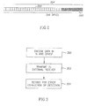
- data such as, for example, sensory data or image data that may have been collected by a device 40 may be packaged or collected into blocks, for example, block 204.
- a block 204 of data may include 256 bytes of, for example, image data, which may be included in sub block 202.
- block 204 may include 768 bytes of image data which may be included in sub block 202.
- Other block sizes or data formats may be used.
- a processor such as, for example, processing unit 47 or another component that may be included in device 40 may add to such block 204 of data an additional one or more bytes (or other data units) which may include error correction or detection data, such as parity bits.
- the bytes (or other data units) including error correction or detection codes may be included in sub block 200.
- sub block 200 is located at the end of block 204 for illustrative purposes, however, according to embodiments of the invention, bytes including error correction or detection data may located in other locations within block 204. In some embodiments, approximately 1/5 of the bytes of block 204 may include error correction or detection codes. Other number of bytes or bits which include error correction or detection data may be used.
- not all 8 bits in each byte of, for example, the bytes in sub block 202, may be protected. For example, in some embodiments only the most significant bits (e.g., 6 bits out of 8) may be protected by error correction coding.
- Blocks 204 of data including sub block 200 which is added in accordance with error correction code algorithms may be transmitted, for example, by transmitter 41 to a receiver 12.
- the receiving unit may decode, reconstruct, correct or otherwise process the data, or such operations (or a portion of such operations) may be performed by a unit that receiver 12 passes the received data to, such as data processor 14.
- original data may be modified by addition of an error correction or detection code, for example, by using extension coding.
- the original data such as image data in a block or other data unit may be unmodified by the addition of error correction or detection codes, for example, by using systematic coding.
- a receiver that is not equipped with error correction decoding algorithms or a decoder may receive and process the image data without interference from the data information symbols that may have been inserted by the error correction code algorithm.
- a component such as for example data processor 14 or another processor within or connected to receiver 12 may include instructions in for example a decoder 15, that when executed may decode data in a block 204.
- processor 14 may be separate from receiver 12.
- error correction codes may be capable of correcting or accounting for up to 4 or 5 corrupted bits within block 204. Other numbers of corrected bits are possible.
- Fig. 3 is a flow chart of a method of including error correction codes in data transmitted by an in-vivo sensing device in accordance with an exemplary embodiment of the invention.
- a component of an in-vivo sensing device such as an encoder or a processing unit, may add data, such as, for example, parity bits or other error correction code symbols to, for example, a block of image data that was collected by the in-vivo device
- the error correction codes may be based on or employ block coding, convolution coding, trellis coding, turbo coding, or another suitable coding scheme.
- the collected image data which includes error correction codes may be transmitted from the in-vivo imaging device to an external receiver.
- error correction codes e.g., parity bits or other data inserted by the error correction code algorithm or an encoder
- a data processor or other decoder that may be included or connected to a receiver may decode the received data.
- a component of an in-vivo sensing device such as an encoder or a processing unit, may add data, such as, for example, parity bits or other error correction and/or detection code symbols to, for example, a block of image data that was collected by the in-vivo device.
- the encoded data may be transmitted to an external receiving unit (block 402).
- a decoding algorithm and/or correcting code e.g., CRC
- the amount e.g., number or ratio
- the amount of errors may be determined to be above or below a predetermined threshold (block 408).
- the detection (406) and/or determination (408) may be carried out in decoder 15 or in any other appropriate component of the system according to embodiments of the invention.
- a decision may be made, for example, in decoder 15, to delete or abort a row (e.g., sub block 202), a pixel (byte) or even an entire frame, if the amount of errors detected was determined to be above a predetermined threshold.
- a decision made be made to perform a corrective action e.g., by interpolating or employing other appropriate image processing or other signal processing techniques. For example, a decision may be made to substitute corrupted data, for example, by interpolation of correct data.
- a decision may be made to ignore the errors detected if their amount was determined to be under a predetermined threshold.
- a decision can be made to correct the errors detected if their amount was determined to be under a predetermined threshold.
- a predetermined threshold may be the maxirnal number that the specific error correction code can repair.
- the step of determining if the amount of errors is above or below a predetermined threshold may be a trigger for activating and/or altering the operational mode of the in vivo device. For example, if the amount of errors detected is determined to be above a predetermined threshold a decision can be made to change transmission parameters, such as transmission power, transmission rate, the error correction algorithm to be used or other parameters for example, to improve the quality of transmission.
- decoder 15 or any other suitable component can based on a determining step, send a signal, for example to receiver unit 49 (Fig. 1) to control parameters of the in vivo device operation (e.g., to alter transmission power, change transmission rate, etc.).
Landscapes
- Life Sciences & Earth Sciences (AREA)
- Health & Medical Sciences (AREA)
- Engineering & Computer Science (AREA)
- Surgery (AREA)
- Physics & Mathematics (AREA)
- Molecular Biology (AREA)
- Public Health (AREA)
- Veterinary Medicine (AREA)
- Biophysics (AREA)
- Pathology (AREA)
- General Health & Medical Sciences (AREA)
- Animal Behavior & Ethology (AREA)
- Biomedical Technology (AREA)
- Heart & Thoracic Surgery (AREA)
- Medical Informatics (AREA)
- Computer Networks & Wireless Communication (AREA)
- Signal Processing (AREA)
- Optics & Photonics (AREA)
- Radiology & Medical Imaging (AREA)
- Nuclear Medicine, Radiotherapy & Molecular Imaging (AREA)
- Endoscopes (AREA)
- Detection And Prevention Of Errors In Transmission (AREA)
- Measurement Of The Respiration, Hearing Ability, Form, And Blood Characteristics Of Living Organisms (AREA)
Applications Claiming Priority (2)
| Application Number | Priority Date | Filing Date | Title |
|---|---|---|---|
| US873497 | 1986-06-12 | ||
| US10/873,497 US20050288595A1 (en) | 2004-06-23 | 2004-06-23 | Device, system and method for error detection of in-vivo data |
Publications (2)
| Publication Number | Publication Date |
|---|---|
| EP1610485A2 true EP1610485A2 (fr) | 2005-12-28 |
| EP1610485A3 EP1610485A3 (fr) | 2007-05-09 |
Family
ID=35094369
Family Applications (1)
| Application Number | Title | Priority Date | Filing Date |
|---|---|---|---|
| EP05105580A Withdrawn EP1610485A3 (fr) | 2004-06-23 | 2005-06-23 | Dispositif, système et procédé de détection d'erreurs des données in vivo |
Country Status (3)
| Country | Link |
|---|---|
| US (1) | US20050288595A1 (fr) |
| EP (1) | EP1610485A3 (fr) |
| JP (1) | JP2006051336A (fr) |
Cited By (3)
| Publication number | Priority date | Publication date | Assignee | Title |
|---|---|---|---|---|
| WO2009036245A1 (fr) | 2007-09-14 | 2009-03-19 | Capso Vision, Inc. | Communication de données entre une caméra encapsulée et ses environnements externes |
| EP2407083A1 (fr) * | 2004-09-16 | 2012-01-18 | Olympus Corporation | Endoscope à capsule |
| EP2575354A1 (fr) * | 2011-09-30 | 2013-04-03 | Fujifilm Corporation | Système d'endoscope et dispositif de commande externe pour endoscope |
Families Citing this family (9)
| Publication number | Priority date | Publication date | Assignee | Title |
|---|---|---|---|---|
| JP4526315B2 (ja) * | 2004-07-07 | 2010-08-18 | オリンパス株式会社 | 被検体内導入装置および被検体内情報取得システム |
| US9962098B2 (en) | 2006-06-02 | 2018-05-08 | Global Cardiac Monitors, Inc. | Heart monitor electrode system |
| US8043209B2 (en) * | 2006-06-13 | 2011-10-25 | Given Imaging Ltd. | System and method for transmitting the content of memory storage in an in-vivo sensing device |
| US20080004532A1 (en) * | 2006-06-30 | 2008-01-03 | Kevin Rubey | System and method for transmitting identification data in an in-vivo sensing device |
| JP4416782B2 (ja) * | 2006-12-15 | 2010-02-17 | キヤノン株式会社 | 画像処理装置、決定装置、変更装置、および画像処理方法 |
| WO2009044610A1 (fr) | 2007-10-01 | 2009-04-09 | Olympus Corporation | Dispositif et système médicaux en capsule |
| US20100042012A1 (en) * | 2008-08-15 | 2010-02-18 | Karim Alhussiny | Diagnostic device for remote sensing and transmitting biophysiological signals |
| US20150201858A1 (en) * | 2008-08-15 | 2015-07-23 | Global Cardiac Monitors, Inc. | Diagnostic device for remote sensing and transmitting biophysiological signals |
| EP3500177A1 (fr) * | 2016-08-18 | 2019-06-26 | Mitchell Lawrence Jones | Systèmes d'obtention d'échantillons au moyen de dispositifs ingérables |
Family Cites Families (28)
| Publication number | Priority date | Publication date | Assignee | Title |
|---|---|---|---|---|
| US3683389A (en) * | 1971-01-20 | 1972-08-08 | Corning Glass Works | Omnidirectional loop antenna array |
| US3971362A (en) * | 1972-10-27 | 1976-07-27 | The United States Of America As Represented By The Administrator Of The National Aeronautics And Space Administration | Miniature ingestible telemeter devices to measure deep-body temperature |
| JPS5519124A (en) * | 1978-07-27 | 1980-02-09 | Olympus Optical Co | Camera system for medical treatment |
| US4590924A (en) * | 1983-09-21 | 1986-05-27 | Olympus Optical Co., Ltd. | Endoscope system |
| US4689621A (en) * | 1986-03-31 | 1987-08-25 | The United States Of America As Represented By The Administrator Of The National Aeronautics And Space Administration | Temperature responsive transmitter |
| JPH0664243B2 (ja) * | 1986-04-30 | 1994-08-22 | オリンパス光学工業株式会社 | 内視鏡 |
| US4844076A (en) * | 1988-08-26 | 1989-07-04 | The Johns Hopkins University | Ingestible size continuously transmitting temperature monitoring pill |
| US5279607A (en) * | 1991-05-30 | 1994-01-18 | The State University Of New York | Telemetry capsule and process |
| US5609560A (en) * | 1992-08-19 | 1997-03-11 | Olympus Optical Co., Ltd. | Medical operation device control system for controlling a operation devices accessed respectively by ID codes |
| US5678568A (en) * | 1993-07-27 | 1997-10-21 | Olympus Optical Co., Ltd. | System control apparatus, medical system control apparatus and image-plane display method of medical system control apparatus |
| IL108352A (en) * | 1994-01-17 | 2000-02-29 | Given Imaging Ltd | In vivo video camera system |
| US5819736A (en) * | 1994-03-24 | 1998-10-13 | Sightline Technologies Ltd. | Viewing method and apparatus particularly useful for viewing the interior of the large intestine |
| US5699365A (en) * | 1996-03-27 | 1997-12-16 | Motorola, Inc. | Apparatus and method for adaptive forward error correction in data communications |
| US6240312B1 (en) * | 1997-10-23 | 2001-05-29 | Robert R. Alfano | Remote-controllable, micro-scale device for use in in vivo medical diagnosis and/or treatment |
| US7116352B2 (en) * | 1999-02-25 | 2006-10-03 | Visionsense Ltd. | Capsule |
| US8636648B2 (en) * | 1999-03-01 | 2014-01-28 | West View Research, Llc | Endoscopic smart probe |
| US6638212B1 (en) * | 1999-07-27 | 2003-10-28 | Olympus Optical | Endoscope system having storage part of endoscope-related-data provided in endoscope |
| US6968494B2 (en) * | 2000-05-22 | 2005-11-22 | Sarnoff Corporation | Method and apparatus for adaptively coding a data signal |
| IL151048A0 (en) * | 2000-12-07 | 2003-04-10 | Given Imaging Ltd | Method and system for use of a pointing device with moving images |
| WO2002080376A2 (fr) * | 2001-03-29 | 2002-10-10 | Given Imaging Ltd. | Procede de reglage d'un interrupteur |
| US7119814B2 (en) * | 2001-05-18 | 2006-10-10 | Given Imaging Ltd. | System and method for annotation on a moving image |
| IL143259A (en) * | 2001-05-20 | 2006-08-01 | Given Imaging Ltd | A method of moving a bone in the colon |
| US6939292B2 (en) * | 2001-06-20 | 2005-09-06 | Olympus Corporation | Capsule type endoscope |
| US20030005385A1 (en) * | 2001-06-27 | 2003-01-02 | Stieger Ronald D. | Optical communication system with variable error correction coding |
| US20030028078A1 (en) * | 2001-08-02 | 2003-02-06 | Arkady Glukhovsky | In vivo imaging device, system and method |
| IL153510A0 (en) * | 2001-12-18 | 2003-07-06 | Given Imaging Ltd | Device, system and method for capturing in-vivo images with three-dimensional aspects |
| EP1474927B1 (fr) * | 2002-02-12 | 2007-08-29 | Given Imaging Ltd. | Systeme et procede pour afficher un flux d'images |
| EP1565107A4 (fr) * | 2002-11-14 | 2008-03-05 | Ethicon Endo Surgery Inc | Methodes et dispositifs de detection de cellules tissulaires |
-
2004
- 2004-06-23 US US10/873,497 patent/US20050288595A1/en not_active Abandoned
-
2005
- 2005-06-23 JP JP2005183407A patent/JP2006051336A/ja not_active Withdrawn
- 2005-06-23 EP EP05105580A patent/EP1610485A3/fr not_active Withdrawn
Cited By (7)
| Publication number | Priority date | Publication date | Assignee | Title |
|---|---|---|---|---|
| EP2407083A1 (fr) * | 2004-09-16 | 2012-01-18 | Olympus Corporation | Endoscope à capsule |
| US8421853B2 (en) | 2004-09-16 | 2013-04-16 | Olympus Corporation | Capsule endoscope system |
| WO2009036245A1 (fr) | 2007-09-14 | 2009-03-19 | Capso Vision, Inc. | Communication de données entre une caméra encapsulée et ses environnements externes |
| EP2198342A4 (fr) * | 2007-09-14 | 2012-06-27 | Capso Vision Inc | Communication de données entre une caméra encapsulée et ses environnements externes |
| US9285670B2 (en) | 2007-09-14 | 2016-03-15 | Capso Vision, Inc. | Data communication between capsulated camera and its external environments |
| EP2575354A1 (fr) * | 2011-09-30 | 2013-04-03 | Fujifilm Corporation | Système d'endoscope et dispositif de commande externe pour endoscope |
| US9319568B2 (en) | 2011-09-30 | 2016-04-19 | Fujifilm Corporation | Endoscope system and external control device for endoscope |
Also Published As
| Publication number | Publication date |
|---|---|
| EP1610485A3 (fr) | 2007-05-09 |
| US20050288595A1 (en) | 2005-12-29 |
| JP2006051336A (ja) | 2006-02-23 |
Similar Documents
| Publication | Publication Date | Title |
|---|---|---|
| US20100134606A1 (en) | Diagnostic device, system and method for reduced data transmission | |
| CN100518306C (zh) | 使用数据压缩的诊断器件 | |
| EP1610485A2 (fr) | Dispositif, système et procédé de détection d'erreurs des données in vivo | |
| US9113846B2 (en) | In-vivo imaging device providing data compression | |
| US7492935B2 (en) | Device, method, and system for reduced transmission imaging | |
| AU2002321797A1 (en) | Diagnostic device using data compression | |
| JP5616017B2 (ja) | 定ビットレート伝送を提供するインビボ撮像装置 | |
| JP5203639B2 (ja) | 生体内撮像装置およびレコーダを含む生体内検知システムの作動方法ならびに生体内検知システム | |
| AU2007203033A1 (en) | System and method for transmitting identification data in a in-vivo sensing device | |
| WO2004061420A2 (fr) | Systeme de controle du glucose en continu, et procedes d'utilisation correspondants | |
| US20080004503A1 (en) | Data recorder and method for recording a data signal received from an in-vivo sensing device | |
| US8214724B2 (en) | Transmitting data with variable unit for playback | |
| KR102292404B1 (ko) | 캡슐 내시경, 캡슐 내시경과 연동하는 수신 장치 및 캡슐 내시경 제어 방법 | |
| JP4709514B2 (ja) | カプセル型内視鏡システム | |
| JP2005176973A (ja) | 放射線画像処理装置、放射線画像処理システム、放射線撮影システム、放射線撮影装置、放射線画像処理方法、コンピュータ可読記憶媒体、及びプログラム | |
| JP2012011123A (ja) | 電子内視鏡装置 | |
| CN108155971A (zh) | 数据传输处理方法及食管pH值检测系统数据传输装置 | |
| CN113631073A (zh) | 内窥镜系统和参数控制装置 | |
| KR100964816B1 (ko) | 캡슐내시경에서 영상 데이터의 전송 방법 및 그 캡슐내시경 | |
| JP2010004443A (ja) | 通信システム及び通信方法 | |
| AU2007200474A1 (en) | Diagnostic device using data compression |
Legal Events
| Date | Code | Title | Description |
|---|---|---|---|
| PUAI | Public reference made under article 153(3) epc to a published international application that has entered the european phase |
Free format text: ORIGINAL CODE: 0009012 |
|
| AK | Designated contracting states |
Kind code of ref document: A2 Designated state(s): AT BE BG CH CY CZ DE DK EE ES FI FR GB GR HU IE IS IT LI LT LU MC NL PL PT RO SE SI SK TR |
|
| AX | Request for extension of the european patent |
Extension state: AL BA HR LV MK YU |
|
| PUAL | Search report despatched |
Free format text: ORIGINAL CODE: 0009013 |
|
| AK | Designated contracting states |
Kind code of ref document: A3 Designated state(s): AT BE BG CH CY CZ DE DK EE ES FI FR GB GR HU IE IS IT LI LT LU MC NL PL PT RO SE SI SK TR |
|
| AX | Request for extension of the european patent |
Extension state: AL BA HR LV MK YU |
|
| RAP1 | Party data changed (applicant data changed or rights of an application transferred) |
Owner name: GIVEN IMAGING LTD. |
|
| 17P | Request for examination filed |
Effective date: 20071102 |
|
| AKX | Designation fees paid |
Designated state(s): AT BE BG CH CY CZ DE DK EE ES FI FR GB GR HU IE IS IT LI LT LU MC NL PL PT RO SE SI SK TR |
|
| 17Q | First examination report despatched |
Effective date: 20080222 |
|
| STAA | Information on the status of an ep patent application or granted ep patent |
Free format text: STATUS: THE APPLICATION IS DEEMED TO BE WITHDRAWN |
|
| 18D | Application deemed to be withdrawn |
Effective date: 20080704 |