EP1611773B1 - Module de rayonnement - Google Patents
Module de rayonnement Download PDFInfo
- Publication number
- EP1611773B1 EP1611773B1 EP04725001A EP04725001A EP1611773B1 EP 1611773 B1 EP1611773 B1 EP 1611773B1 EP 04725001 A EP04725001 A EP 04725001A EP 04725001 A EP04725001 A EP 04725001A EP 1611773 B1 EP1611773 B1 EP 1611773B1
- Authority
- EP
- European Patent Office
- Prior art keywords
- radiation
- sources
- reflecting
- cooling
- radiator module
- Prior art date
- Legal status (The legal status is an assumption and is not a legal conclusion. Google has not performed a legal analysis and makes no representation as to the accuracy of the status listed.)
- Expired - Lifetime
Links
Images


Classifications
-
- H—ELECTRICITY
- H05—ELECTRIC TECHNIQUES NOT OTHERWISE PROVIDED FOR
- H05B—ELECTRIC HEATING; ELECTRIC LIGHT SOURCES NOT OTHERWISE PROVIDED FOR; CIRCUIT ARRANGEMENTS FOR ELECTRIC LIGHT SOURCES, IN GENERAL
- H05B3/00—Ohmic-resistance heating
-
- F—MECHANICAL ENGINEERING; LIGHTING; HEATING; WEAPONS; BLASTING
- F26—DRYING
- F26B—DRYING SOLID MATERIALS OR OBJECTS BY REMOVING LIQUID THEREFROM
- F26B3/00—Drying solid materials or objects by processes involving the application of heat
- F26B3/28—Drying solid materials or objects by processes involving the application of heat by radiation, e.g. from the sun
- F26B3/30—Drying solid materials or objects by processes involving the application of heat by radiation, e.g. from the sun from infrared-emitting elements
-
- B—PERFORMING OPERATIONS; TRANSPORTING
- B01—PHYSICAL OR CHEMICAL PROCESSES OR APPARATUS IN GENERAL
- B01J—CHEMICAL OR PHYSICAL PROCESSES, e.g. CATALYSIS OR COLLOID CHEMISTRY; THEIR RELEVANT APPARATUS
- B01J19/00—Chemical, physical or physico-chemical processes in general; Their relevant apparatus
- B01J19/08—Processes employing the direct application of electric or wave energy, or particle radiation; Apparatus therefor
- B01J19/12—Processes employing the direct application of electric or wave energy, or particle radiation; Apparatus therefor employing electromagnetic waves
-
- B—PERFORMING OPERATIONS; TRANSPORTING
- B29—WORKING OF PLASTICS; WORKING OF SUBSTANCES IN A PLASTIC STATE IN GENERAL
- B29C—SHAPING OR JOINING OF PLASTICS; SHAPING OF MATERIAL IN A PLASTIC STATE, NOT OTHERWISE PROVIDED FOR; AFTER-TREATMENT OF THE SHAPED PRODUCTS, e.g. REPAIRING
- B29C35/00—Heating, cooling or curing, e.g. crosslinking or vulcanising; Apparatus therefor
- B29C35/02—Heating or curing, e.g. crosslinking or vulcanizing during moulding, e.g. in a mould
- B29C35/08—Heating or curing, e.g. crosslinking or vulcanizing during moulding, e.g. in a mould by wave energy or particle radiation
-
- F—MECHANICAL ENGINEERING; LIGHTING; HEATING; WEAPONS; BLASTING
- F26—DRYING
- F26B—DRYING SOLID MATERIALS OR OBJECTS BY REMOVING LIQUID THEREFROM
- F26B3/00—Drying solid materials or objects by processes involving the application of heat
- F26B3/28—Drying solid materials or objects by processes involving the application of heat by radiation, e.g. from the sun
-
- G—PHYSICS
- G21—NUCLEAR PHYSICS; NUCLEAR ENGINEERING
- G21K—HANDLING OF PARTICLES OR IONISING RADIATION NOT OTHERWISE PROVIDED FOR; IRRADIATION DEVICES; GAMMA RAY OR X-RAY MICROSCOPES
- G21K5/00—Irradiation devices
- G21K5/04—Irradiation devices with beam-forming means
-
- H—ELECTRICITY
- H05—ELECTRIC TECHNIQUES NOT OTHERWISE PROVIDED FOR
- H05B—ELECTRIC HEATING; ELECTRIC LIGHT SOURCES NOT OTHERWISE PROVIDED FOR; CIRCUIT ARRANGEMENTS FOR ELECTRIC LIGHT SOURCES, IN GENERAL
- H05B3/00—Ohmic-resistance heating
- H05B3/0033—Heating devices using lamps
- H05B3/009—Heating devices using lamps heating devices not specially adapted for a particular application
Definitions
- the invention relates to a radiator module according to the preamble of claim 1.
- an irradiation arrangement for the execution of processes of the above-mentioned type which has a cooled main reflector, the elongated halogen lamps, and laterally arranged therefrom separate side reflectors. These are arranged in particular substantially perpendicular to the plane defined by the center axes of the halogen lamps on the main reflector plane.
- a radiation source with elongated halogen lamps is known, the ends of which are bent towards the glass body and made thickened or compacted.
- the lamp ends are associated with cooling means for heat dissipation, which are to provide a steep T gradient between the bent portions of the glass body and the adjacent electrical terminals.
- a compressed air flow channel is provided for cooling with arranged near the ends of the glass body of the lamps outlet openings for cooling.
- the invention is therefore based on the object of providing an improved radiator module, which can be realized with relatively low cost and yet is largely usable without the use of additional components for a variety of applications.
- the invention includes the essential idea, in a structurally simple and therefore cost-effective way radiation sources (emitters) with rearwardly bent ends in the main reflector integrated end or side reflectors to improve the properties of the radiation field, especially to its homogenization in the side areas to assign. Furthermore, the invention includes the idea of integrally forming these end reflector sections in a technologically advantageous manner to the reflector and heat sink. As a result, additional assembly work and upstream separate manufacturing, handling and Lagerungsvo réelle be avoided, which form a significant cost factor in the preparation of irradiation arrangements of the type outlined above.
- the end reflector sections are substantially flat over the entire width of the radiator module, and they close with the plane of the longitudinal extension of the radiator module, which is parallel to the longitudinal axes of the radiation sources used, an angle in the range between 30 ° and 75 °, preferably between 45 ° and 60 °.
- This embodiment satisfactorily ensures, in most applications, returning radiation emerging laterally from the curved radiator section into the working radiation field above the main reflector section where the elongated central sections of the emitters are located. In particular, this makes it possible in a sufficient manner to avoid a drop in the radiation density in the side or end regions of the radiation field, which lie above the curvature sections of the radiator, without the use of additional side reflectors.
- Endreflektorabitese each rise at an edge of the reflector and heat sink, which is at the same height with the transition from the curvature portion in the end of the radiation sources used in the reflector and heat sink and of the curvature portions of the radiation sources in the longitudinal direction of the reflector and heat sink has a distance which is in particular in the range between half and full diameter of a radiation source.
- the radiator module is a suitable coordination between the inclination of the Endreflektktorabroughe with respect to the plane of the longitudinal extent make the emitter and the distance of the "footer" of Endreflektorabroughe of the curvature regions of the radiator, which accomplished in any case the expert with a few simple experiments.
- the end reflector sections in the height direction of the reflector and heat sink extend to at most a plane spanned by the center axes of the adjacent radiation sources above the reflector and heat sink. This makes it possible to limit the length and height of the reflector and heat sink in a meaningful way without having to make inappropriate compromises in terms of the radiation density distribution in the irradiation zone.
- radiator module in which cooling ribs for realizing fan-air cooling are formed on the rear side of the reflector and heat sink facing away from the radiation sources.
- This design makes low demands on an existing user infrastructure.
- the invention can also be implemented in a design with a liquid-cooled reflector body, in which - in a manner known per se - fluid flow channels for passing a cooling fluid (cooling water) are formed.
- the aforementioned air-cooled design can be further developed in terms of production engineering and cooling technology in such a way that side walls are formed on the reflector and heat sink, which protrude above the height of the cooling ribs in particular and are connected by a rear wall.
- the cooling fins are characterized in a substantially closed, in Lä ngsraum the radiator module extending cooling air duct. At these a blower outlet can be connected substantially tight, so that a highly effective air cooling is realized, which remains virtually without affecting the surrounding equipment parts, the respective workpiece and the operator.
- the reflector and heat sink are expediently arranged on the outside of the rear wall of the cooling air duct, fixing and connecting means for holding and external electrical contacting of the radiation sources.
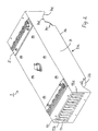
- NIR radiator module 1 for thermal processing tasks in perspective views from above (the reflector top provided with emitters 3) or from below (provided with terminal strips 5 back) ago.
- the heart of the radiator module 1 is a one-piece reflector and heat sink 7. On its reflector top 7a are arranged in the embodiment shown here six emitters 3 (operated as an NIR radiator with elevated operating temperature halogen filament lamps), each having a glass body with a rectilinear elongated central portion 3a, on both sides of these subsequent curved sections 3b and turn to these subsequent end or socket sections 3c include.
- emitters 3 operted as an NIR radiator with elevated operating temperature halogen filament lamps
- the reflector top 7a of the reflector and heat sink 7 is provided in the central region with a plurality of aligned in alignment with the arrangement of emitters parallel to each other main reflector sections 7b, which have a substantially W-shaped cross-section ,
- the reflector top side 7a of the reflector and heat sink has a quarter-circle-shaped curved section 7c in longitudinal section. This in turn is followed in each case by a plane parallel to the plane of the longitudinal extent of the emitter 3, but opposite this set Hughes flat portion 7d.
- the reflector top side 7a has an end reflector section 7e inclined at 45 ° with respect to the flat sections 7d and thus also the plane of the longitudinal extension of the emitter 3 at 45 °.
- the emitters 3 are each guided through a circular feedthrough opening 9 in the flat section 7 d of the reflector upper side 7 a of the reflector and cooler body.
- the end reflector portions 7e have a (not separately designated) foot line from which they emanate from the flat portions 7d, which in the illustrated embodiment is offset by approximately half the diameter of the lamp from the outermost points of the emitters 3 and feedthrough openings 9, respectively.
- the end reflector portions 7e are (as can be seen most clearly in Fig. 3c) pulled up to almost the plane of the main reflector sections 7b upwards.
- cooling fins 11 extending in the longitudinal direction are provided, and a closed cooling air channel 15 is formed in the reflector and cooling body 3 by means of the side walls 13a and 13b projecting beyond them and a rear wall 13c connecting them.
- FIGS. 3A to 3D show details of this arrangement, wherein, in particular in FIGS. 3B and 3D, it becomes clear that the end portions 3c of the emitters 3 are aligned with cooling fins - each second cooling fin 11 in such a way the area of which is securely held and nevertheless sufficiently exposed to a cooling air flow passing through the cooling air duct 15 in order to achieve effective lamp end cooling.
- suitable plug contacts 17 the structural design is not the subject of the present application
- the lamp ends 3 c are electrically and mechanically connected to the terminal strips 5.
Landscapes
- Engineering & Computer Science (AREA)
- General Engineering & Computer Science (AREA)
- Life Sciences & Earth Sciences (AREA)
- Microbiology (AREA)
- Mechanical Engineering (AREA)
- Chemical & Material Sciences (AREA)
- Health & Medical Sciences (AREA)
- Physics & Mathematics (AREA)
- Combustion & Propulsion (AREA)
- Toxicology (AREA)
- Oral & Maxillofacial Surgery (AREA)
- Thermal Sciences (AREA)
- Electromagnetism (AREA)
- General Health & Medical Sciences (AREA)
- Organic Chemistry (AREA)
- Chemical Kinetics & Catalysis (AREA)
- High Energy & Nuclear Physics (AREA)
- Arrangement Of Elements, Cooling, Sealing, Or The Like Of Lighting Devices (AREA)
- Physical Or Chemical Processes And Apparatus (AREA)
- Led Device Packages (AREA)
Claims (9)
- Module de rayonnement pour processus de traitements thermiques ou aux UV, comportant une pluralité de sources de rayonnement électromagnétique disposées pour l'essentiel les unes à côté des autres et parallèlement les unes par rapport aux autres, dont l'essentiel de la proportion active figure dans le domaine des UV, le domaine visible et/ou le domaine de l'IR proche, en particulier dans une plage de longueurs d'onde comprise entre 250 nm et 1,5 µm, les sources de rayonnement présentant chaque fois une section médiane allongée, deux extrémités coudées et deux sections de courbure reliant la section médiane et les extrémités, et un corps réflecteur et de refroidissement supportant les sources de rayonnement,
caractérisé en ce que
le corps réflecteur et de refroidissement présente deux sections de réflecteur d'extrémité, formées de façon monobloc, affectées aux sections de courbure des sources de rayonnement depuis la section principale allongée en ligne droite jusqu'aux extrémités. - Module de rayonnement selon la revendication 1,
caractérisé en ce que
les sections de réflecteur d'extrémité sont sensiblement planes sur la totalité de la largeur du module de rayonnement et forment un angle dans la plage des 30 ° à 75 °, de préférence de 45 ° à 60 °, avec le plan de l'extension longitudinale du module de rayonnement figurant parallèlement à l'axe longitudinal des sources de rayonnement logées. - Module de rayonnement selon la revendication 1 ou 2,
caractérisé en ce que
les sections de réflecteur d'extrémité s'élèvent chaque fois par une arête hors du corps réflecteur et de refroidissement, figurant à la même hauteur que la transition de la section de courbure en l'extrémité des sources de rayonnement disposées dans le corps réflecteur et de refroidissement et qui présente un écartement par rapport aux sections de courbure des sources de rayonnement dans la direction longitudinale du corps réflecteur et de refroidissement appartenant, en particulier, à la plage de la moitié au diamètre total d'une source de rayonnement. - Module de rayonnement selon l'une quelconque des revendications 1 à 3,
caractérisé en ce que
les sections de réflecteur d'extrémité, dans la direction de la hauteur du corps réflecteur et de refroidissement, atteignent au plus un plan au-dessus du corps réflecteur et de refroidissement passant par les axes médians des sources de rayonnement situées côte à côte. - Module de rayonnement selon l'une quelconque des revendications précédentes,
caractérisé en ce que,
au côté arrière détourné des sources de rayonnement du corps réflecteur et de refroidissement, des nervures de refroidissement sont formées pour réaliser un refroidissement à air par soufflerie. - Module de rayonnement selon la revendication 5,
caractérisé en ce que
le corps réflecteur et de refroidissement comporte des parois latérales dépassant la hauteur des nervures de refroidissement et une paroi arrière les reliant, de manière telle que les nervures de refroidissement sont reprises par un canal d'air de refroidissement, pour l'essentiel fermé, disposé dans la direction longitudinale du corps réflecteur et de refroidissement. - Module de rayonnement selon la revendication 5 ou 6,
caractérisé en ce que
les extrémités des sources de rayonnement et les dispositifs de contact électrique affectés sont alignés avec des nervures de refroidissement et disposés de manière telle dans des découpes des nervures de refroidissement qu'ils sont frappés par le flux d'air de refroidissement circulant à la surface des nervures de refroidissement. - Module de rayonnement selon la revendication 6 ou 7,
caractérisé en ce que
des moyens de fixation et de raccordement sont disposés sur le côté extérieur de la paroi arrière du canal d'air de refroidissement pour le maintien et la mise en contact électrique externe des sources de rayonnement. - Module de rayonnement selon l'une quelconque des revendications précédentes,
caractérisé en ce que
le corps réflecteur et de refroidissement est réalisé de façon monobloc.
Applications Claiming Priority (2)
| Application Number | Priority Date | Filing Date | Title |
|---|---|---|---|
| DE10315260A DE10315260A1 (de) | 2003-04-03 | 2003-04-03 | Strahlermodul |
| PCT/EP2004/003476 WO2004088713A2 (fr) | 2003-04-03 | 2004-04-01 | Module de rayonnement |
Publications (2)
| Publication Number | Publication Date |
|---|---|
| EP1611773A2 EP1611773A2 (fr) | 2006-01-04 |
| EP1611773B1 true EP1611773B1 (fr) | 2007-03-07 |
Family
ID=33016146
Family Applications (1)
| Application Number | Title | Priority Date | Filing Date |
|---|---|---|---|
| EP04725001A Expired - Lifetime EP1611773B1 (fr) | 2003-04-03 | 2004-04-01 | Module de rayonnement |
Country Status (6)
| Country | Link |
|---|---|
| US (1) | US7372054B2 (fr) |
| EP (1) | EP1611773B1 (fr) |
| KR (1) | KR101074317B1 (fr) |
| AT (1) | ATE356525T1 (fr) |
| DE (2) | DE10315260A1 (fr) |
| WO (1) | WO2004088713A2 (fr) |
Families Citing this family (4)
| Publication number | Priority date | Publication date | Assignee | Title |
|---|---|---|---|---|
| DE102006028702B4 (de) * | 2006-06-22 | 2009-06-25 | Advanced Photonics Technologies Ag | Bestrahlungseinrichtung |
| DE202017006537U1 (de) * | 2017-12-21 | 2018-01-19 | Gunther Ackermann | Vorrichtung zur Bestrahlung eines Gegenstandes |
| DE102018126309B4 (de) | 2018-10-23 | 2024-06-06 | Khs Gmbh | Heizanordnung zur Erwärmung von Vorformlingen aus thermoplastischem Material und Heizstrahlelement für eine Heizanordnung |
| CN109927405B (zh) * | 2019-04-18 | 2021-03-02 | 绍兴柯桥佳宇兴腾染整有限公司 | 一种可均匀加热空气的印染产品烘干设备 |
Family Cites Families (9)
| Publication number | Priority date | Publication date | Assignee | Title |
|---|---|---|---|---|
| DE853784C (de) * | 1950-06-14 | 1952-10-27 | Harold Ernest Scotton | Strahlungs-Heizgeraet |
| DE3317812A1 (de) * | 1983-05-17 | 1984-11-22 | Friedrich 7800 Freiburg Wolff | Bestrahlungs- oder beleuchtungsgeraet |
| US5194401A (en) * | 1989-04-18 | 1993-03-16 | Applied Materials, Inc. | Thermally processing semiconductor wafers at non-ambient pressures |
| FR2711014A1 (fr) * | 1993-10-04 | 1995-04-14 | Gen Electric | Lampe à quartz à deux extrémités et procédé de fabrication de cette lampe. |
| SE513409C2 (sv) * | 1997-07-01 | 2000-09-11 | Kanthal Ab | IR-källa som utgörs av ett spiralformat högtemperaturelement, vilket är placerat i en öppen reflektor |
| JP3438658B2 (ja) * | 1999-07-22 | 2003-08-18 | ウシオ電機株式会社 | ランプユニット及び光照射式加熱装置 |
| DE20020149U1 (de) * | 2000-09-18 | 2001-03-22 | Advanced Photonics Tech Ag | Strahlungsquelle und Bestrahlungsanordnung |
| DE20020148U1 (de) * | 2000-09-18 | 2001-03-22 | Advanced Photonics Technologies AG, 83052 Bruckmühl | Strahlungsquelle und Bestrahlungsanordnung |
| DE10238253B4 (de) * | 2002-08-21 | 2007-12-13 | Advanced Photonics Technologies Ag | UV-Bestrahlungsanlage zur Erzeugung eines ausgedehnten UV-Strahlungsfeldes |
-
2003
- 2003-04-03 DE DE10315260A patent/DE10315260A1/de not_active Withdrawn
-
2004
- 2004-04-01 AT AT04725001T patent/ATE356525T1/de not_active IP Right Cessation
- 2004-04-01 KR KR1020057018856A patent/KR101074317B1/ko not_active Expired - Fee Related
- 2004-04-01 EP EP04725001A patent/EP1611773B1/fr not_active Expired - Lifetime
- 2004-04-01 WO PCT/EP2004/003476 patent/WO2004088713A2/fr not_active Ceased
- 2004-04-01 DE DE502004003139T patent/DE502004003139D1/de not_active Expired - Lifetime
- 2004-04-01 US US10/551,846 patent/US7372054B2/en not_active Expired - Lifetime
Also Published As
| Publication number | Publication date |
|---|---|
| DE10315260A1 (de) | 2004-10-21 |
| US7372054B2 (en) | 2008-05-13 |
| US20060208192A1 (en) | 2006-09-21 |
| WO2004088713A3 (fr) | 2005-04-21 |
| DE502004003139D1 (de) | 2007-04-19 |
| KR20060017751A (ko) | 2006-02-27 |
| WO2004088713A2 (fr) | 2004-10-14 |
| ATE356525T1 (de) | 2007-03-15 |
| KR101074317B1 (ko) | 2011-10-17 |
| EP1611773A2 (fr) | 2006-01-04 |
Similar Documents
| Publication | Publication Date | Title |
|---|---|---|
| EP2151278B1 (fr) | Dispositif de rayonnement | |
| EP2556296A1 (fr) | Boîtier de lampe | |
| EP3322951A1 (fr) | Unité de rayonnement à led de conception modulaire et utilisation de ladite unité | |
| EP1319240B1 (fr) | Source et dispositif de rayonnement | |
| EP0959645A2 (fr) | Radiateur à infrarouge à courtes longueurs d'ondes | |
| DE202020002017U1 (de) | Vorrichtung zur Bestrahlung eines Substrates | |
| EP1611773B1 (fr) | Module de rayonnement | |
| DE10051641B4 (de) | Bestrahlungsanordnung | |
| DE10051904B4 (de) | Strahlungsquelle und Bestrahlungsanordnung | |
| EP0469430A2 (fr) | Lampe électrique | |
| DE102018101503B4 (de) | Elektrische Steckverbindung zum Verbinden eines Leuchtmittels mit einer elektrischen Anschlussleitung | |
| WO2002023591A1 (fr) | Source de rayonnement et dispositif de rayonnement | |
| EP3686481B1 (fr) | Dissipateur thermique pour une platine del | |
| DE10051905B4 (de) | Strahlungsquelle und Bestrahlungsanordnung | |
| DE3619919C2 (de) | Quarz-Infrarotstrahler | |
| DE10316908A1 (de) | Heizvorrichtung | |
| EP1524892A2 (fr) | Circuit pourvu d'un radiateur pour alimenter une lampe | |
| DE102017124853A1 (de) | Optisches System für eine LED-Leuchte | |
| DE10051642B4 (de) | Bestrahlungsanordnung | |
| DE202010008309U1 (de) | LED-Lampe | |
| EP1521499A1 (fr) | Dispositif pour connecteur destiné à un dispositif de chauffage muni d'éléments PTC, en particulier pour véhicule automobile | |
| DE10257432B4 (de) | Luftgekühlte Bestrahlungsanordnung | |
| DE20020319U1 (de) | Bestrahlungsanordnung | |
| EP4732632A1 (fr) | Radiateur infrarouge électrique | |
| DE20020320U1 (de) | Bestrahlungsanordnung |
Legal Events
| Date | Code | Title | Description |
|---|---|---|---|
| PUAI | Public reference made under article 153(3) epc to a published international application that has entered the european phase |
Free format text: ORIGINAL CODE: 0009012 |
|
| 17P | Request for examination filed |
Effective date: 20051031 |
|
| AK | Designated contracting states |
Kind code of ref document: A2 Designated state(s): AT BE BG CH CY CZ DE DK EE ES FI FR GB GR HU IE IT LI LU MC NL PL PT RO SE SI SK TR |
|
| AX | Request for extension of the european patent |
Extension state: AL HR LT LV MK |
|
| GRAP | Despatch of communication of intention to grant a patent |
Free format text: ORIGINAL CODE: EPIDOSNIGR1 |
|
| DAX | Request for extension of the european patent (deleted) | ||
| GRAS | Grant fee paid |
Free format text: ORIGINAL CODE: EPIDOSNIGR3 |
|
| GRAA | (expected) grant |
Free format text: ORIGINAL CODE: 0009210 |
|
| AK | Designated contracting states |
Kind code of ref document: B1 Designated state(s): AT BE BG CH CY CZ DE DK EE ES FI FR GB GR HU IE IT LI LU MC NL PL PT RO SE SI SK TR |
|
| PG25 | Lapsed in a contracting state [announced via postgrant information from national office to epo] |
Ref country code: FI Free format text: LAPSE BECAUSE OF FAILURE TO SUBMIT A TRANSLATION OF THE DESCRIPTION OR TO PAY THE FEE WITHIN THE PRESCRIBED TIME-LIMIT Effective date: 20070307 Ref country code: PL Free format text: LAPSE BECAUSE OF FAILURE TO SUBMIT A TRANSLATION OF THE DESCRIPTION OR TO PAY THE FEE WITHIN THE PRESCRIBED TIME-LIMIT Effective date: 20070307 Ref country code: IE Free format text: LAPSE BECAUSE OF FAILURE TO SUBMIT A TRANSLATION OF THE DESCRIPTION OR TO PAY THE FEE WITHIN THE PRESCRIBED TIME-LIMIT Effective date: 20070307 Ref country code: SI Free format text: LAPSE BECAUSE OF FAILURE TO SUBMIT A TRANSLATION OF THE DESCRIPTION OR TO PAY THE FEE WITHIN THE PRESCRIBED TIME-LIMIT Effective date: 20070307 Ref country code: NL Free format text: LAPSE BECAUSE OF FAILURE TO SUBMIT A TRANSLATION OF THE DESCRIPTION OR TO PAY THE FEE WITHIN THE PRESCRIBED TIME-LIMIT Effective date: 20070307 |
|
| REG | Reference to a national code |
Ref country code: GB Ref legal event code: FG4D Free format text: NOT ENGLISH |
|
| REG | Reference to a national code |
Ref country code: CH Ref legal event code: EP |
|
| REF | Corresponds to: |
Ref document number: 502004003139 Country of ref document: DE Date of ref document: 20070419 Kind code of ref document: P |
|
| REG | Reference to a national code |
Ref country code: IE Ref legal event code: FG4D Free format text: LANGUAGE OF EP DOCUMENT: GERMAN |
|
| GBT | Gb: translation of ep patent filed (gb section 77(6)(a)/1977) |
Effective date: 20070502 |
|
| PG25 | Lapsed in a contracting state [announced via postgrant information from national office to epo] |
Ref country code: SE Free format text: LAPSE BECAUSE OF FAILURE TO SUBMIT A TRANSLATION OF THE DESCRIPTION OR TO PAY THE FEE WITHIN THE PRESCRIBED TIME-LIMIT Effective date: 20070607 |
|
| PG25 | Lapsed in a contracting state [announced via postgrant information from national office to epo] |
Ref country code: ES Free format text: LAPSE BECAUSE OF FAILURE TO SUBMIT A TRANSLATION OF THE DESCRIPTION OR TO PAY THE FEE WITHIN THE PRESCRIBED TIME-LIMIT Effective date: 20070618 |
|
| PG25 | Lapsed in a contracting state [announced via postgrant information from national office to epo] |
Ref country code: PT Free format text: LAPSE BECAUSE OF FAILURE TO SUBMIT A TRANSLATION OF THE DESCRIPTION OR TO PAY THE FEE WITHIN THE PRESCRIBED TIME-LIMIT Effective date: 20070807 |
|
| NLV1 | Nl: lapsed or annulled due to failure to fulfill the requirements of art. 29p and 29m of the patents act | ||
| ET | Fr: translation filed | ||
| REG | Reference to a national code |
Ref country code: IE Ref legal event code: FD4D |
|
| PG25 | Lapsed in a contracting state [announced via postgrant information from national office to epo] |
Ref country code: SK Free format text: LAPSE BECAUSE OF FAILURE TO SUBMIT A TRANSLATION OF THE DESCRIPTION OR TO PAY THE FEE WITHIN THE PRESCRIBED TIME-LIMIT Effective date: 20070307 |
|
| BERE | Be: lapsed |
Owner name: ADVANCED PHOTONICS TECHNOLOGIES A.G. Effective date: 20070430 |
|
| PG25 | Lapsed in a contracting state [announced via postgrant information from national office to epo] |
Ref country code: RO Free format text: LAPSE BECAUSE OF FAILURE TO SUBMIT A TRANSLATION OF THE DESCRIPTION OR TO PAY THE FEE WITHIN THE PRESCRIBED TIME-LIMIT Effective date: 20070307 Ref country code: CZ Free format text: LAPSE BECAUSE OF FAILURE TO SUBMIT A TRANSLATION OF THE DESCRIPTION OR TO PAY THE FEE WITHIN THE PRESCRIBED TIME-LIMIT Effective date: 20070307 |
|
| PLBE | No opposition filed within time limit |
Free format text: ORIGINAL CODE: 0009261 |
|
| STAA | Information on the status of an ep patent application or granted ep patent |
Free format text: STATUS: NO OPPOSITION FILED WITHIN TIME LIMIT |
|
| PG25 | Lapsed in a contracting state [announced via postgrant information from national office to epo] |
Ref country code: DK Free format text: LAPSE BECAUSE OF FAILURE TO SUBMIT A TRANSLATION OF THE DESCRIPTION OR TO PAY THE FEE WITHIN THE PRESCRIBED TIME-LIMIT Effective date: 20070307 |
|
| 26N | No opposition filed |
Effective date: 20071210 |
|
| PG25 | Lapsed in a contracting state [announced via postgrant information from national office to epo] |
Ref country code: BE Free format text: LAPSE BECAUSE OF NON-PAYMENT OF DUE FEES Effective date: 20070430 |
|
| PG25 | Lapsed in a contracting state [announced via postgrant information from national office to epo] |
Ref country code: GR Free format text: LAPSE BECAUSE OF FAILURE TO SUBMIT A TRANSLATION OF THE DESCRIPTION OR TO PAY THE FEE WITHIN THE PRESCRIBED TIME-LIMIT Effective date: 20070608 |
|
| PG25 | Lapsed in a contracting state [announced via postgrant information from national office to epo] |
Ref country code: AT Free format text: LAPSE BECAUSE OF NON-PAYMENT OF DUE FEES Effective date: 20070401 |
|
| REG | Reference to a national code |
Ref country code: CH Ref legal event code: PL |
|
| PG25 | Lapsed in a contracting state [announced via postgrant information from national office to epo] |
Ref country code: LI Free format text: LAPSE BECAUSE OF NON-PAYMENT OF DUE FEES Effective date: 20080430 Ref country code: EE Free format text: LAPSE BECAUSE OF FAILURE TO SUBMIT A TRANSLATION OF THE DESCRIPTION OR TO PAY THE FEE WITHIN THE PRESCRIBED TIME-LIMIT Effective date: 20070307 Ref country code: CH Free format text: LAPSE BECAUSE OF NON-PAYMENT OF DUE FEES Effective date: 20080430 |
|
| PG25 | Lapsed in a contracting state [announced via postgrant information from national office to epo] |
Ref country code: MC Free format text: LAPSE BECAUSE OF NON-PAYMENT OF DUE FEES Effective date: 20070430 |
|
| PG25 | Lapsed in a contracting state [announced via postgrant information from national office to epo] |
Ref country code: CY Free format text: LAPSE BECAUSE OF FAILURE TO SUBMIT A TRANSLATION OF THE DESCRIPTION OR TO PAY THE FEE WITHIN THE PRESCRIBED TIME-LIMIT Effective date: 20070307 |
|
| PG25 | Lapsed in a contracting state [announced via postgrant information from national office to epo] |
Ref country code: LU Free format text: LAPSE BECAUSE OF NON-PAYMENT OF DUE FEES Effective date: 20070401 Ref country code: BG Free format text: LAPSE BECAUSE OF FAILURE TO SUBMIT A TRANSLATION OF THE DESCRIPTION OR TO PAY THE FEE WITHIN THE PRESCRIBED TIME-LIMIT Effective date: 20070607 |
|
| PG25 | Lapsed in a contracting state [announced via postgrant information from national office to epo] |
Ref country code: TR Free format text: LAPSE BECAUSE OF FAILURE TO SUBMIT A TRANSLATION OF THE DESCRIPTION OR TO PAY THE FEE WITHIN THE PRESCRIBED TIME-LIMIT Effective date: 20070307 Ref country code: HU Free format text: LAPSE BECAUSE OF FAILURE TO SUBMIT A TRANSLATION OF THE DESCRIPTION OR TO PAY THE FEE WITHIN THE PRESCRIBED TIME-LIMIT Effective date: 20070908 |
|
| REG | Reference to a national code |
Ref country code: GB Ref legal event code: 732E Free format text: REGISTERED BETWEEN 20100318 AND 20100324 |
|
| REG | Reference to a national code |
Ref country code: GB Ref legal event code: 732E Free format text: REGISTERED BETWEEN 20100325 AND 20100331 |
|
| REG | Reference to a national code |
Ref country code: FR Ref legal event code: PLFP Year of fee payment: 12 |
|
| PGFP | Annual fee paid to national office [announced via postgrant information from national office to epo] |
Ref country code: GB Payment date: 20150430 Year of fee payment: 12 |
|
| PGFP | Annual fee paid to national office [announced via postgrant information from national office to epo] |
Ref country code: FR Payment date: 20150430 Year of fee payment: 12 Ref country code: IT Payment date: 20150430 Year of fee payment: 12 |
|
| PGFP | Annual fee paid to national office [announced via postgrant information from national office to epo] |
Ref country code: DE Payment date: 20150629 Year of fee payment: 12 |
|
| REG | Reference to a national code |
Ref country code: DE Ref legal event code: R119 Ref document number: 502004003139 Country of ref document: DE |
|
| GBPC | Gb: european patent ceased through non-payment of renewal fee |
Effective date: 20160401 |
|
| REG | Reference to a national code |
Ref country code: FR Ref legal event code: ST Effective date: 20161230 |
|
| PG25 | Lapsed in a contracting state [announced via postgrant information from national office to epo] |
Ref country code: FR Free format text: LAPSE BECAUSE OF NON-PAYMENT OF DUE FEES Effective date: 20160502 Ref country code: GB Free format text: LAPSE BECAUSE OF NON-PAYMENT OF DUE FEES Effective date: 20160401 Ref country code: DE Free format text: LAPSE BECAUSE OF NON-PAYMENT OF DUE FEES Effective date: 20161101 |
|
| PG25 | Lapsed in a contracting state [announced via postgrant information from national office to epo] |
Ref country code: IT Free format text: LAPSE BECAUSE OF NON-PAYMENT OF DUE FEES Effective date: 20160401 |