EP1612084B1 - Elektrisch unterstütztes Fahrrad - Google Patents
Elektrisch unterstütztes Fahrrad Download PDFInfo
- Publication number
- EP1612084B1 EP1612084B1 EP05014180A EP05014180A EP1612084B1 EP 1612084 B1 EP1612084 B1 EP 1612084B1 EP 05014180 A EP05014180 A EP 05014180A EP 05014180 A EP05014180 A EP 05014180A EP 1612084 B1 EP1612084 B1 EP 1612084B1
- Authority
- EP
- European Patent Office
- Prior art keywords
- motor
- state
- battery
- bicycle
- control unit
- Prior art date
- Legal status (The legal status is an assumption and is not a legal conclusion. Google has not performed a legal analysis and makes no representation as to the accuracy of the status listed.)
- Expired - Lifetime
Links
Images

Classifications
-
- B—PERFORMING OPERATIONS; TRANSPORTING
- B60—VEHICLES IN GENERAL
- B60L—PROPULSION OF ELECTRICALLY-PROPELLED VEHICLES; SUPPLYING ELECTRIC POWER FOR AUXILIARY EQUIPMENT OF ELECTRICALLY-PROPELLED VEHICLES; ELECTRODYNAMIC BRAKE SYSTEMS FOR VEHICLES IN GENERAL; MAGNETIC SUSPENSION OR LEVITATION FOR VEHICLES; MONITORING OPERATING VARIABLES OF ELECTRICALLY-PROPELLED VEHICLES; ELECTRIC SAFETY DEVICES FOR ELECTRICALLY-PROPELLED VEHICLES
- B60L7/00—Electrodynamic brake systems for vehicles in general
- B60L7/10—Dynamic electric regenerative braking
- B60L7/18—Controlling the braking effect
-
- B—PERFORMING OPERATIONS; TRANSPORTING
- B60—VEHICLES IN GENERAL
- B60L—PROPULSION OF ELECTRICALLY-PROPELLED VEHICLES; SUPPLYING ELECTRIC POWER FOR AUXILIARY EQUIPMENT OF ELECTRICALLY-PROPELLED VEHICLES; ELECTRODYNAMIC BRAKE SYSTEMS FOR VEHICLES IN GENERAL; MAGNETIC SUSPENSION OR LEVITATION FOR VEHICLES; MONITORING OPERATING VARIABLES OF ELECTRICALLY-PROPELLED VEHICLES; ELECTRIC SAFETY DEVICES FOR ELECTRICALLY-PROPELLED VEHICLES
- B60L50/00—Electric propulsion with power supplied within the vehicle
- B60L50/20—Electric propulsion with power supplied within the vehicle using propulsion power generated by humans or animals
-
- B—PERFORMING OPERATIONS; TRANSPORTING
- B60—VEHICLES IN GENERAL
- B60L—PROPULSION OF ELECTRICALLY-PROPELLED VEHICLES; SUPPLYING ELECTRIC POWER FOR AUXILIARY EQUIPMENT OF ELECTRICALLY-PROPELLED VEHICLES; ELECTRODYNAMIC BRAKE SYSTEMS FOR VEHICLES IN GENERAL; MAGNETIC SUSPENSION OR LEVITATION FOR VEHICLES; MONITORING OPERATING VARIABLES OF ELECTRICALLY-PROPELLED VEHICLES; ELECTRIC SAFETY DEVICES FOR ELECTRICALLY-PROPELLED VEHICLES
- B60L50/00—Electric propulsion with power supplied within the vehicle
- B60L50/40—Electric propulsion with power supplied within the vehicle using propulsion power supplied by capacitors
-
- B—PERFORMING OPERATIONS; TRANSPORTING
- B60—VEHICLES IN GENERAL
- B60L—PROPULSION OF ELECTRICALLY-PROPELLED VEHICLES; SUPPLYING ELECTRIC POWER FOR AUXILIARY EQUIPMENT OF ELECTRICALLY-PROPELLED VEHICLES; ELECTRODYNAMIC BRAKE SYSTEMS FOR VEHICLES IN GENERAL; MAGNETIC SUSPENSION OR LEVITATION FOR VEHICLES; MONITORING OPERATING VARIABLES OF ELECTRICALLY-PROPELLED VEHICLES; ELECTRIC SAFETY DEVICES FOR ELECTRICALLY-PROPELLED VEHICLES
- B60L50/00—Electric propulsion with power supplied within the vehicle
- B60L50/50—Electric propulsion with power supplied within the vehicle using propulsion power supplied by batteries or fuel cells
- B60L50/51—Electric propulsion with power supplied within the vehicle using propulsion power supplied by batteries or fuel cells characterised by AC-motors
-
- B—PERFORMING OPERATIONS; TRANSPORTING
- B60—VEHICLES IN GENERAL
- B60L—PROPULSION OF ELECTRICALLY-PROPELLED VEHICLES; SUPPLYING ELECTRIC POWER FOR AUXILIARY EQUIPMENT OF ELECTRICALLY-PROPELLED VEHICLES; ELECTRODYNAMIC BRAKE SYSTEMS FOR VEHICLES IN GENERAL; MAGNETIC SUSPENSION OR LEVITATION FOR VEHICLES; MONITORING OPERATING VARIABLES OF ELECTRICALLY-PROPELLED VEHICLES; ELECTRIC SAFETY DEVICES FOR ELECTRICALLY-PROPELLED VEHICLES
- B60L7/00—Electrodynamic brake systems for vehicles in general
- B60L7/24—Electrodynamic brake systems for vehicles in general with additional mechanical or electromagnetic braking
- B60L7/26—Controlling the braking effect
-
- B—PERFORMING OPERATIONS; TRANSPORTING
- B62—LAND VEHICLES FOR TRAVELLING OTHERWISE THAN ON RAILS
- B62M—RIDER PROPULSION OF WHEELED VEHICLES OR SLEDGES; POWERED PROPULSION OF SLEDGES OR SINGLE-TRACK CYCLES; TRANSMISSIONS SPECIALLY ADAPTED FOR SUCH VEHICLES
- B62M6/00—Rider propulsion of wheeled vehicles with additional source of power, e.g. combustion engine or electric motor
- B62M6/40—Rider propelled cycles with auxiliary electric motor
- B62M6/45—Control or actuating devices therefor
-
- B—PERFORMING OPERATIONS; TRANSPORTING
- B62—LAND VEHICLES FOR TRAVELLING OTHERWISE THAN ON RAILS
- B62M—RIDER PROPULSION OF WHEELED VEHICLES OR SLEDGES; POWERED PROPULSION OF SLEDGES OR SINGLE-TRACK CYCLES; TRANSMISSIONS SPECIALLY ADAPTED FOR SUCH VEHICLES
- B62M6/00—Rider propulsion of wheeled vehicles with additional source of power, e.g. combustion engine or electric motor
- B62M6/80—Accessories, e.g. power sources; Arrangements thereof
- B62M6/90—Batteries
-
- B—PERFORMING OPERATIONS; TRANSPORTING
- B60—VEHICLES IN GENERAL
- B60L—PROPULSION OF ELECTRICALLY-PROPELLED VEHICLES; SUPPLYING ELECTRIC POWER FOR AUXILIARY EQUIPMENT OF ELECTRICALLY-PROPELLED VEHICLES; ELECTRODYNAMIC BRAKE SYSTEMS FOR VEHICLES IN GENERAL; MAGNETIC SUSPENSION OR LEVITATION FOR VEHICLES; MONITORING OPERATING VARIABLES OF ELECTRICALLY-PROPELLED VEHICLES; ELECTRIC SAFETY DEVICES FOR ELECTRICALLY-PROPELLED VEHICLES
- B60L2200/00—Type of vehicles
- B60L2200/12—Bikes
-
- B—PERFORMING OPERATIONS; TRANSPORTING
- B60—VEHICLES IN GENERAL
- B60L—PROPULSION OF ELECTRICALLY-PROPELLED VEHICLES; SUPPLYING ELECTRIC POWER FOR AUXILIARY EQUIPMENT OF ELECTRICALLY-PROPELLED VEHICLES; ELECTRODYNAMIC BRAKE SYSTEMS FOR VEHICLES IN GENERAL; MAGNETIC SUSPENSION OR LEVITATION FOR VEHICLES; MONITORING OPERATING VARIABLES OF ELECTRICALLY-PROPELLED VEHICLES; ELECTRIC SAFETY DEVICES FOR ELECTRICALLY-PROPELLED VEHICLES
- B60L2250/00—Driver interactions
- B60L2250/16—Driver interactions by display
-
- Y—GENERAL TAGGING OF NEW TECHNOLOGICAL DEVELOPMENTS; GENERAL TAGGING OF CROSS-SECTIONAL TECHNOLOGIES SPANNING OVER SEVERAL SECTIONS OF THE IPC; TECHNICAL SUBJECTS COVERED BY FORMER USPC CROSS-REFERENCE ART COLLECTIONS [XRACs] AND DIGESTS
- Y02—TECHNOLOGIES OR APPLICATIONS FOR MITIGATION OR ADAPTATION AGAINST CLIMATE CHANGE
- Y02T—CLIMATE CHANGE MITIGATION TECHNOLOGIES RELATED TO TRANSPORTATION
- Y02T10/00—Road transport of goods or passengers
- Y02T10/60—Other road transportation technologies with climate change mitigation effect
- Y02T10/70—Energy storage systems for electromobility, e.g. batteries
Definitions
- the present invention relates to a method for controlling a regenerative state of a motor of an electrically assisted bicycle which is driven with human power and with auxiliary power afforded by an assisting power device.
- auxiliary power given by an electric motor or like power device is used for assisting in running in addition to the force produced by the rider by pedaling so as to reduce the pedaling force to be produced by the rider.
- the electrically assisted bicycles disclosed in these publications are adapted to perform regenerative braking when the brake lever is manipulated. Accordingly, the charging by regenerative braking can be effected only when the brake is actuated on descents, failing to fully increase the cycling distance.
- EP 0 994 015 A2 is concerned with a bicycle with power assisting function that have a human power drive mechanism for producing a drive force with human power, a battery adapted for discharging and recharging, an electric power drive mechanism including an electric motor for producing a drive force with electric power output from the battery, speed detecting means for detecting the running speed of the bicycle and a control unit for controlling the electric motor of the power drive mechanism.
- the electric motor can be operated as an electric generator for utilizing part of regenerated electric energy to recharge the battery.
- a regenerating mode is set to regenerate electric energy.
- EP 0 798 204 A1 discloses a regeneration control device for a bicycle with an auxiliary motor wherein the auxiliary motor can be used as a generator for generating electric power to recharge the battery.
- the re-generation control device judges the necessity of regeneration based on the bicycle speed detected by a bicycle speed detection means and pressing force detected by pressing force detection means and changes the motor to a state of regeneration according to the detected speed and pressing force.
- the regenerating state is set when the bicycle speed is higher than a certain value and the pressing force is lower than a certain level.
- An object of the present invention which has been accomplished to solve the above problem, is to provide a method for controlling a regenerative state of a motor of an electrically assisted bicycle to remarkably increase the cycling distance by effectively utilizing auxiliary power.
- the battery can be charged by effectively utilizing the running energy of the bicycle, whereby the cycling distance can be increased remarkably.
- the battery is charged only while the bicycle is running at a speed not lower than the predetermined value, and the bicycle is assisted with the drive force of the electric power drive mechanism when running at a speed below the predetermined value. Accordingly, no trouble occurs in the stability of running at a low speed range.
- the regenerative state is changed over to the nonregenerative state, the running efficiency will not be impaired. Since a changeover takes place when a lower running speed remains for the specified period of time, a changeover from the regenerative state to the nonregenerative state and vice verse will not occur frequently, whereby a stabilized state of running can be ensured.
- a changeover between an "economical charging” mode wherein the motor is set in the regenerative state when the running speed detected by the speed detecting means is not lower than the predetermined value and a "standard mode" wherein the motor is set in the nonregenerative state irrespective of the running speed detected by the speed detecting means is effected by changeover means.
- the battery can be charged by effectively utilizing the running energy of the bicycle when the "economical charging” mode is selected, whereby the cycling distance can be increased remarkably.
- the battery is charged in the "economical charging” mode only while the bicycle is running at a speed not lower than the predetermined value, and the bicycle is assisted with the drive force of the electric power drive mechanism when running at a speed below the predetermined value. Accordingly, no trouble occurs in the stability of running at a low speed range.
- the rider can select the "economical charging" mode or the "standard” mode as required, with the result that the bicycle is usable with improved convenience.
- charging of the battery with the power generated by the motor is interrupted by the control unit when the remaining capacity of the battery is not lower than a specified value.
- the control unit interrupts the charging of the battery with the power generated by the motor. This obviates the likelihood of the battery becoming overcharged.
- charging of the battery with the power generated by the motor is interrupted by the control unit when the running speed detected by the speed detecting means is not lower than a given value.
- the control unit interrupts the charging of the battery with the power generated by the motor. This obviates the likelihood of the battery becoming overcharged.
- regenerative braking upon detecting braking to charge the battery is effected by the control unit. Since the control unit performs regenerative braking upon detecting the application of the brake, improved safety will result, while the battery can be charged by the regenerative braking, whereby the cycling distance can further be increased.
- the pedaling force of the bicycle is detected by means of a pedal torque sensor, and the regenerative state is changed over by the control unit to the nonregenerative state when the running speed detected by the speed detecting means is below the predetermined value and when the pedaling force detected by the pedal torque sensor is not lower than a specified value.
- the regenerative state is changed over to the nonregenerative state when the running speed drops and when the pedaling force is not lower than the specified value.
- the electric power to be generated by the motor is set at a greater value as the running speed detected by the speed detecting means increases.
- the battery can be charged to a greater level utilizing the excessive force of the rider, consequently serving to further increase the cycling distance.
- the auxiliary power of the electric power drive mechanism in the nonregenerative state is set by the control unit (13) at a lower value when selecting the "economical charging” mode than when selecting the "standard” mode.
- the auxiliary power of the electric power drive mechanism in the nonregenerative state is set at a lower value when in the "economical charging” mode than when in the "standard” mode, so that the consumption of the power of the battery can be diminished to result in a further increase in the cycling distance.
- Electrically assisted bicycles comprise a human power drive mechanism for transmitting the pedaling force of the rider from pedals to a wheel via a crank, chain, etc., an electric power drive mechanism including an electric motor serving as a drive source for assisting the pedaling force of the human power mechanism and a battery which is adapted for discharging and recharging for supplying electric power to the electric power drive mechanism.
- FIG. 1 is a block diagram showing control means of an electrically assisting bicycle
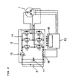
- FIG. 2 is a diagram showing a charge-discharge circuit of the bicycle.
- an electric motor 1 is coupled to an unillustrated bicycle wheel for transmitting power thereto.
- the motor rotates the wheel with the electric power supplied from a battery 3 through the charge-discharge circuit 2.
- the battery 3 is charged with the power generated utilizing the rotation of the wheel.
- the state in which the wheel is rotated with the electric power supplied from the battery 3 will hereinafter be referred to as the "nonregenerative state,” and the state in which the battery 3 is charged with the power generated utilizing the rotation of the wheel as the "regenerative state.”
- Indicated at 4 is a torque sensor for detecting the pedaling force exerted on the pedals.
- a speed detecting means 5 detects the running speed of the bicycle from the rotational speed of the motor 1.
- a braking sensor 6 detects the actuation of the brake of the bicycle.
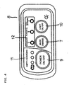
- a mode setting switch 7 is provided on a manipulation unit 8 mountable in the vicinity of the handle and to be described later, and is used by the rider.
- FIG. 3 shows the manipulation unit 8 provided with the mode setting switch 7.
- the bicycle is set for one of operating modes, i.e., "standard,” “powerful” and “economical charging” (hereinafter referred to briefly as “eco-charging").
- the manipulation unit 8 is provided, in addition to the mode setting switch 7, with a power source switch 9, lighting switch 10 for on-off controlling a light serving as the unillustrated headlight of the bicycle, battery empty indicator 11, and mode indicator 12 for indicating the mode selected by the mode setting switch 7.
- Indicated at 13 is a control unit for receiving signals from the torque sensor 4, speed detecting means 5, braking sensor 6, mode setting switch 7, power source switch 9 and lighting switch 10 and controlling the charge-discharge circuit 2, battery empty indicator 11, mode indicator 12 and the unillustrated light.
- a MOSFET circuit 14 is provided between the motor 1 and the battery 3 for controlling the motor 1.
- An FET 15 is connected between the MOSFET circuit 14 and the positive electrode of the battery 3.
- the MOSFET circuit 14 and the FET 15 are controlled by a drive circuit 16 of the control unit 13. Indicated at 17 is a capacitor, and at 18 a resistor.
- the drive circuit 16 turns off the FET 15, preventing the electromotive force of the motor 1 from increasing and charging the battery 3. If the electromotive force of the motor 1 increases during running at a high speed, and the output voltage of the battery 3 becomes 24 V or higher according to the embodiment, the battery 3 is likely to be charged and become overcharged. Accordingly, when the running speed is at least a given value, the FET 15 is turned off to prevent overcharging.
- the given speed is a value sufficiently higher than a predetermined speed of step 6 to be described later and at least a speed at which the battery 3 is undesirably charged with the electromotive force of the motor 1.
- the control unit 13 further detects the remaining capacity of the battery 3, and when the remaining capacity is not smaller than a predetermined value, i.e., at least 90% according to the embodiment, the control unit 13 turns off the FET 15 to prevent the battery 3 from being overcharged with the power to be generated by the motor 1 as when the brake is actuated. Overcharging is prevented in this way even in the case where any of the "standard” mode, "powerful” mode and “eco-charging” mode is selected.
- the FET 15 is connected between the battery 3 and the MOSFET circuit 14 for controlling the connection between the battery 3 and the MOSFET 14, whereas other component capable of controlling the connection, such as a relay, may alternatively be used.
- the torque sensor 4 detects the pedaling force, whereupon the motor 1 is driven in accordance with the pedaling force to add an auxiliary force of the motor 1 to the human pedaling force and run the bicycle.
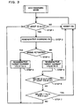
- the bicycle speed setting switch 7 When the "eco-charging" mode is set by the mode setting switch 7, an inquiry is made as to whether the bicycle speed is not lower than a predetermined value, i.e., at least 12 kg/h in the present embodiment, with reference to the speed detecting means 5 as shown in the flow chart of FIG. 3 (step 1). If the running speed is less than the predetermined value, the bicycle is brought into a nonregenerative state to add to the pedaling force auxiliary power of the motor 1 in accordance with the pedaling force for running the bicycle. This auxiliary power is set 50% of the power in the "standard" mode to diminish the consumption of the battery 3.
- a predetermined value i.e., at least 12 kg/h in the present embodiment
- step 1 When the speed is found to be at least the predetermined value in step 1, the mode is changed over to the regenerative state, in which power is generated by the motor 1 to charge the battery 3 (step 2). At this time, an inquiry is made as to whether the brake is applied (step 3). When the inquiry is answered in the negative, the bicycle is in the usual state of running. If great current is produced, running load increases, so that a current value of 0.8 A is generated for charging the battery 3 (step 4). If the brake is on, regenerative braking can be utilized to obtain great current. Current of up to 6 A is therefore generated for charging the battery 3 (step 5). The greater the speed, the greater the current value to be generation by this regenerative braking is and the greater the braking force feels, so that improved safety can be achieved on descents.
- the regenerative state is promptly changed over to the nonregenerative state since the rider will be greatly burdened in the regenerative state (step 6).
- the regenerative state is changed over to the nonregenerative state in the case where the bicycle remains at a speed less than the predetermined value, i.e., less than 11 km/h according to the present embodiment, for a specified period of time, i.e., for 3 seconds (sep 7). This specified period of time is provided to avoid frequent changeovers between the regenerative state and the nonregenerative state.
- the auxiliary power of the motor 1 is greater than in the "eco-charging” mode, the motor is not brought into the regenerative state but is held in the nonregenerative state even if the speed is not lower than the predetermined value.
- the motor is brought into the regenerative state only when the brake is actuated.
- the auxiliary power of the motor 1 is greater than in the "standard” mode to lessen the burden on the rider.
- the charging current value may be increased as the running speed increases.
- the speed detecting means 5 is adapted to detect the running speed by detecting the rotation of the motor 1, the rotation of the wheel of the bicycle may be detected for the calculation of the running speed, or other detecting structure may be used.
Landscapes
- Engineering & Computer Science (AREA)
- Transportation (AREA)
- Mechanical Engineering (AREA)
- Power Engineering (AREA)
- Chemical & Material Sciences (AREA)
- Combustion & Propulsion (AREA)
- Life Sciences & Earth Sciences (AREA)
- Sustainable Development (AREA)
- Sustainable Energy (AREA)
- Physics & Mathematics (AREA)
- Electromagnetism (AREA)
- Electric Propulsion And Braking For Vehicles (AREA)
Claims (8)
- Verfahren zum Steuern eines regenerativen Zustands eines Motors eines elektrisch unterstützten Fahrrads, wobei das Fahrrad umfasst:- einen Antriebsmechanismus für menschliche Leistung, um mit menschlicher Leistung eine Antriebskraft zu erzeugen,- eine Batterie (3), die entladen und wieder aufgeladen werden kann,- einen Antriebsmechanismus für elektrische Leistung, der einen Elektromotor (1) enthält, um eine Antriebskraft mit von der Batterie (3) ausgegebener elektrischer Leistung zu erzeugen, wobei der Elektromotor (1) zwischen einem regenerativen Zustand und einem nicht regenerativen Zustand umschaltbar ist, um im regenerativen Zustand elektrische Leistung anhand der kinetischen Energie des Fahrrads zu erzeugen, um die Batterie (3) aufzuladen, und um im nicht regenerativen Zustand die Erzeugung von Leistung zu unterbrechen,- ein Geschwindigkeitserfassungsmittel (5), um die Fahrgeschwindigkeit des Fahrrads zu erfassen, und- eine Steuereinheit (13), um den Motor (1) einzustellen,wobei das Verfahren den folgenden Schritt umfasst:- Einstellen des Motors (1) durch die Steuereinheit (13) in den regenerativen Zustand, wenn die von dem Geschwindigkeitserfassungsmittel (5) erfasste Fahrgeschwindigkeit nicht niedriger als ein vorgegebener Wert ist,gekennzeichnet durch- Umschalten des regenerativen Zustands des Motors (1) in den nicht regenerativen Zustand durch die Steuereinheit (13), wenn die durch das Geschwindigkeitserfassungsmittel (5) erfasste Fahrgeschwindigkeit für eine bestimmte Zeitdauer unter dem vorgegebenen Wert bleibt.
- Verfahren nach Anspruch 1, wobei ein Umschalten zwischen einer "wirtschaftlichen Ladebetriebsart", in der der Motor (1) in den regenerativen Zustand versetzt ist, wenn die durch das Geschwindigkeitserfassungsmittel (5) erfasste Fahrgeschwindigkeit nicht niedriger als der vorgegebene Wert ist, und einer "Standardbetriebsart", in der der Motor (1) unabhängig von der durch das Geschwindigkeitserfassungsmittel (5) erfassten Fahrgeschwindigkeit in den nicht regenerativen Zustand versetzt ist, durch das Umschaltmittel ausgeführt wird.
- Verfahren nach Anspruch 1, wobei das Aufladen der Batterie (3) mit der durch den Motor (1) erzeugten Leistung durch die Steuereinheit (13) unterbrochen wird, wenn die verbleibende Kapazität der Batterie (3) nicht niedriger als ein bestimmter Wert ist.
- Verfahren nach Anspruch 1, wobei das Aufladen der Batterie (3) mit der durch den Motor (1) erzeugten Leistung durch die Steuereinheit (13) unterbrochen wird, wenn die durch das Geschwindigkeitserfassungsmittel (5) erfasste Fahrgeschwindigkeit nicht niedriger als ein gegebener Wert ist.
- Verfahren nach einem der Ansprüche 1 bis 4, wobei durch die Steuereinheit (13) ein regeneratives Bremsen ausgeführt wird, wenn ein Bremsvorgang erfasst wird, um die Batterie (3) aufzuladen.
- Verfahren nach einem der Ansprüche 1 bis 4, wobei- die Pedalkraft des Fahrrads mittels eines Pedaldrehmomentsensors (4) erfasst wird und- der regenerative Zustand durch die Steuereinheit (13) in den nicht regenerativen Zustand umgeschaltet wird, wenn die durch das Geschwindigkeitserfassungsmittel erfasste Fahrgeschwindigkeit unter dem vorgegebenen Wert liegt und wenn die durch den Pedaldrehmomentsensor (4) erfasste Pedalkraft nicht niedriger als ein vorgegebener Wert ist.
- Verfahren nach einem der Ansprüche 1 bis 4, wobei die durch den Motor (1) zu erzeugende elektrische Leistung auf einen größeren Wert gesetzt wird, wenn die durch das Geschwindigkeitserfassungsmittel (5) erfasste Fahrgeschwindigkeit ansteigt.
- Verfahren nach Anspruch 2, wobei die Steuereinheit (13) die Hilfsleistung des Antriebsmechanismus für elektrische Leistung im nicht regenerativen Zustand dann, wenn die "wirtschaftliche Ladebetriebsart" gewählt ist, auf einen Wert einstellt, der niedriger ist als jener, der eingestellt wird, wenn die "Standardbetriebsart" gewählt ist.
Applications Claiming Priority (1)
| Application Number | Priority Date | Filing Date | Title |
|---|---|---|---|
| JP2004196272A JP2006015887A (ja) | 2004-07-02 | 2004-07-02 | 電動補助自転車 |
Publications (2)
| Publication Number | Publication Date |
|---|---|
| EP1612084A1 EP1612084A1 (de) | 2006-01-04 |
| EP1612084B1 true EP1612084B1 (de) | 2009-02-25 |
Family
ID=34937726
Family Applications (1)
| Application Number | Title | Priority Date | Filing Date |
|---|---|---|---|
| EP05014180A Expired - Lifetime EP1612084B1 (de) | 2004-07-02 | 2005-06-30 | Elektrisch unterstütztes Fahrrad |
Country Status (6)
| Country | Link |
|---|---|
| EP (1) | EP1612084B1 (de) |
| JP (1) | JP2006015887A (de) |
| CN (1) | CN100410138C (de) |
| CA (1) | CA2511260C (de) |
| DE (1) | DE602005012888D1 (de) |
| TW (1) | TWI289125B (de) |
Families Citing this family (35)
| Publication number | Priority date | Publication date | Assignee | Title |
|---|---|---|---|---|
| JP4853378B2 (ja) * | 2007-05-18 | 2012-01-11 | 株式会社ダイフク | ピッキング作業用台車 |
| JP4877827B2 (ja) * | 2007-09-20 | 2012-02-15 | 三洋電機株式会社 | 電動車輌 |
| JP5160882B2 (ja) * | 2007-12-27 | 2013-03-13 | 本田技研工業株式会社 | モータ駆動回路 |
| KR100913501B1 (ko) | 2009-06-08 | 2009-08-21 | 주식회사 삼현 | 하이브리드 자전거의 제어방법 |
| KR100912404B1 (ko) | 2009-06-08 | 2009-08-14 | 주식회사 삼현 | 자전거 및 그의 전력제어방법 |
| US8602149B2 (en) * | 2009-08-10 | 2013-12-10 | Evantage Limited | Motorized bicycle with trainer mode |
| JP2011173457A (ja) * | 2010-02-23 | 2011-09-08 | Sanyo Electric Co Ltd | モータ制御装置、モータ駆動システム及び電動自転車 |
| JP5537994B2 (ja) * | 2010-03-01 | 2014-07-02 | 三洋電機株式会社 | 電動補助自転車 |
| JP5174855B2 (ja) | 2010-06-11 | 2013-04-03 | 株式会社シマノ | 自転車用の電動機制御システム |
| JP5073015B2 (ja) * | 2010-06-11 | 2012-11-14 | 株式会社シマノ | 自転車用回生制動制御装置 |
| JP5106603B2 (ja) * | 2010-08-30 | 2012-12-26 | 株式会社シマノ | 自転車用回生制動制御装置 |
| JP5564389B2 (ja) * | 2010-09-30 | 2014-07-30 | 本田技研工業株式会社 | 電動補助自転車の制御装置 |
| US20120145469A1 (en) * | 2010-12-14 | 2012-06-14 | Gabriel Yui Lung Tong | Wheeled device with lever pedal mechanism |
| JP5211181B2 (ja) * | 2011-01-14 | 2013-06-12 | 三洋電機株式会社 | 電動補助自転車 |
| IT1404164B1 (it) | 2011-02-03 | 2013-11-15 | Milano Politecnico | Bicicletta a pedalata assistita elettricamente |
| KR20130025822A (ko) | 2011-09-02 | 2013-03-12 | 삼성에스디아이 주식회사 | 모터를 구비한 전기기기의 배터리 충전 장치 및 방법 |
| JP2013209077A (ja) * | 2012-02-27 | 2013-10-10 | Honda Motor Co Ltd | 電動アシスト自転車 |
| EP2868562A4 (de) * | 2012-06-28 | 2016-03-02 | Murata Manufacturing Co | Steuervorrichtung einer bewegungsvorrichtung mit hilfsaggregat und bewegungsvorrichtung mit hilfsaggregat mit dieser steuervorrichtung |
| CN103507644A (zh) * | 2012-06-29 | 2014-01-15 | 凹凸电子(武汉)有限公司 | 里程装置和方法、及电动车控制器 |
| KR101309514B1 (ko) * | 2012-09-19 | 2013-10-14 | 주식회사 만도 | 전기 자전거 구동 장치 |
| KR102220897B1 (ko) | 2014-09-03 | 2021-02-26 | 삼성에스디아이 주식회사 | 전기 이동수단 |
| DE102015102345A1 (de) | 2015-02-19 | 2016-08-25 | Dr. Ing. H.C. F. Porsche Aktiengesellschaft | Verfahren zum Laden eines Akkumulators |
| ITUB20155621A1 (it) * | 2015-11-16 | 2017-05-16 | Piaggio & C Spa | Metodo di gestione dell?autonomia energetica di una bicicletta elettrica a pedalata assistita |
| JP2017100540A (ja) | 2015-12-01 | 2017-06-08 | ヤマハ発動機株式会社 | 電動補助自転車 |
| IT201600080022A1 (it) * | 2016-07-29 | 2018-01-29 | Zehus S P A | Dinamo per bicicletta |
| IT201700003184A1 (it) * | 2017-01-13 | 2018-07-13 | Zehus S P A | Sistema adattativo per il controllo di una bicicletta a pedalata assistita |
| JP6817113B2 (ja) * | 2017-03-10 | 2021-01-20 | 株式会社シマノ | 自転車用制御装置およびこの制御装置を含む自転車用駆動装置 |
| JP2019119345A (ja) * | 2018-01-05 | 2019-07-22 | 太陽誘電株式会社 | モータ駆動制御装置及び電動アシスト車 |
| JP7269315B2 (ja) * | 2018-01-05 | 2023-05-08 | 太陽誘電株式会社 | モータ駆動制御装置及び電動アシスト車 |
| CN110077517A (zh) * | 2018-01-26 | 2019-08-02 | 上海腾通信息科技有限公司 | 一种混合动力电助力车及其控制方法 |
| JP6927902B2 (ja) * | 2018-02-09 | 2021-09-01 | 株式会社シマノ | 人力駆動車両用制御装置 |
| WO2020066208A1 (ja) * | 2018-09-28 | 2020-04-02 | 本田技研工業株式会社 | 鞍乗型電動車両 |
| JP7731871B2 (ja) * | 2020-03-30 | 2025-09-01 | パナソニックエナジー株式会社 | 電動自転車用の電池パックとこの電池パックを備える電動自転車 |
| TWI790579B (zh) | 2021-03-25 | 2023-01-21 | 宏碁股份有限公司 | 用於電動輔助腳踏車的驅動裝置以及驅動方法 |
| CN115140231B (zh) * | 2021-03-31 | 2023-10-13 | 宏碁股份有限公司 | 用于电动辅助脚踏车的驱动装置以及驱动方法 |
Family Cites Families (8)
| Publication number | Priority date | Publication date | Assignee | Title |
|---|---|---|---|---|
| US3921745A (en) * | 1973-07-23 | 1975-11-25 | Mcculloch Corp | Electric bicycle |
| IL71233A (en) * | 1984-03-14 | 1986-11-30 | Iliya Goldenfeld | Auxiliary drive for pedal-driven road vehicles |
| JPH09254861A (ja) | 1996-03-26 | 1997-09-30 | Yazaki Corp | 電動補助動力自転車 |
| JP3642364B2 (ja) * | 1996-03-29 | 2005-04-27 | 本田技研工業株式会社 | 補助動力付き自転車の回生制御装置 |
| JPH10147150A (ja) | 1996-11-20 | 1998-06-02 | Kanto Auto Works Ltd | ラゲージドア付設式ランプにおける水垂れ防止構造 |
| JP2000118477A (ja) * | 1998-10-12 | 2000-04-25 | Sony Corp | 助力機能付き自転車 |
| CN2352441Y (zh) * | 1998-10-14 | 1999-12-08 | 林煜财 | 具双动力的机车动力结构 |
| US6157149A (en) * | 1999-09-17 | 2000-12-05 | Tokyo R&D Co., Ltd. | Kinetic energy regenerating device for an electric motor bicycle |
-
2004
- 2004-07-02 JP JP2004196272A patent/JP2006015887A/ja active Pending
-
2005
- 2005-05-19 TW TW094116277A patent/TWI289125B/zh not_active IP Right Cessation
- 2005-06-30 CA CA2511260A patent/CA2511260C/en not_active Expired - Fee Related
- 2005-06-30 DE DE602005012888T patent/DE602005012888D1/de not_active Expired - Lifetime
- 2005-06-30 EP EP05014180A patent/EP1612084B1/de not_active Expired - Lifetime
- 2005-07-01 CN CNB2005100821841A patent/CN100410138C/zh not_active Expired - Fee Related
Also Published As
| Publication number | Publication date |
|---|---|
| TWI289125B (en) | 2007-11-01 |
| CA2511260C (en) | 2014-04-15 |
| TW200607701A (en) | 2006-03-01 |
| CA2511260A1 (en) | 2006-01-02 |
| CN100410138C (zh) | 2008-08-13 |
| DE602005012888D1 (de) | 2009-04-09 |
| JP2006015887A (ja) | 2006-01-19 |
| CN1715134A (zh) | 2006-01-04 |
| EP1612084A1 (de) | 2006-01-04 |
Similar Documents
| Publication | Publication Date | Title |
|---|---|---|
| EP1612084B1 (de) | Elektrisch unterstütztes Fahrrad | |
| CN100551770C (zh) | 电动自行车 | |
| EP1886913B1 (de) | Elektrisch unterstütztes Fahrrad | |
| JP6669422B1 (ja) | 自己充電で走行可能な電動自転車 | |
| JP2005520472A (ja) | 電気車両のための回生ブレーキシステム | |
| JP2003204602A (ja) | 電動車両の回生制御装置 | |
| CN102442397A (zh) | 电动助力自行车的控制装置 | |
| WO2012014396A1 (ja) | 電動自転車 | |
| JP2005063682A (ja) | バッテリ冷却制御装置 | |
| CN111017103A (zh) | 助力自行车 | |
| TWI733136B (zh) | 馬達控制裝置、方法及電動輔助車 | |
| JP2010187479A (ja) | 電動車 | |
| JP2002291104A (ja) | 電動車両のバッテリー制御装置 | |
| JP5931025B2 (ja) | 電動機付自転車 | |
| JPH08140212A (ja) | 回生制御装置 | |
| CN107878662B (zh) | 马达驱动控制装置及电动辅助车 | |
| JP5931024B2 (ja) | 電動機付自転車 | |
| JPH10271607A (ja) | 電気自動車の制動制御装置 | |
| JP5326333B2 (ja) | 車両用電源システム | |
| JP3327162B2 (ja) | 電気自転車 | |
| JP5150317B2 (ja) | 電動自転車 | |
| JP3917337B2 (ja) | シリーズハイブリッド式電動車両 | |
| JPH09123982A (ja) | 補助動力付き自転車 | |
| JPH11139368A (ja) | 自転車用発電装置 | |
| JP7774998B2 (ja) | 電動車両 |
Legal Events
| Date | Code | Title | Description |
|---|---|---|---|
| PUAI | Public reference made under article 153(3) epc to a published international application that has entered the european phase |
Free format text: ORIGINAL CODE: 0009012 |
|
| AK | Designated contracting states |
Kind code of ref document: A1 Designated state(s): AT BE BG CH CY CZ DE DK EE ES FI FR GB GR HU IE IS IT LI LT LU MC NL PL PT RO SE SI SK TR |
|
| AX | Request for extension of the european patent |
Extension state: AL BA HR LV MK YU |
|
| 17P | Request for examination filed |
Effective date: 20060614 |
|
| AKX | Designation fees paid |
Designated state(s): BE DE FR GB IT NL |
|
| 17Q | First examination report despatched |
Effective date: 20070201 |
|
| GRAP | Despatch of communication of intention to grant a patent |
Free format text: ORIGINAL CODE: EPIDOSNIGR1 |
|
| GRAS | Grant fee paid |
Free format text: ORIGINAL CODE: EPIDOSNIGR3 |
|
| GRAA | (expected) grant |
Free format text: ORIGINAL CODE: 0009210 |
|
| AK | Designated contracting states |
Kind code of ref document: B1 Designated state(s): BE DE FR GB IT NL |
|
| REG | Reference to a national code |
Ref country code: GB Ref legal event code: FG4D |
|
| REF | Corresponds to: |
Ref document number: 602005012888 Country of ref document: DE Date of ref document: 20090409 Kind code of ref document: P |
|
| PG25 | Lapsed in a contracting state [announced via postgrant information from national office to epo] |
Ref country code: NL Free format text: LAPSE BECAUSE OF FAILURE TO SUBMIT A TRANSLATION OF THE DESCRIPTION OR TO PAY THE FEE WITHIN THE PRESCRIBED TIME-LIMIT Effective date: 20090225 |
|
| NLV1 | Nl: lapsed or annulled due to failure to fulfill the requirements of art. 29p and 29m of the patents act | ||
| PG25 | Lapsed in a contracting state [announced via postgrant information from national office to epo] |
Ref country code: BE Free format text: LAPSE BECAUSE OF FAILURE TO SUBMIT A TRANSLATION OF THE DESCRIPTION OR TO PAY THE FEE WITHIN THE PRESCRIBED TIME-LIMIT Effective date: 20090225 |
|
| PLBE | No opposition filed within time limit |
Free format text: ORIGINAL CODE: 0009261 |
|
| STAA | Information on the status of an ep patent application or granted ep patent |
Free format text: STATUS: NO OPPOSITION FILED WITHIN TIME LIMIT |
|
| 26N | No opposition filed |
Effective date: 20091126 |
|
| REG | Reference to a national code |
Ref country code: FR Ref legal event code: ST Effective date: 20100226 |
|
| PG25 | Lapsed in a contracting state [announced via postgrant information from national office to epo] |
Ref country code: FR Free format text: LAPSE BECAUSE OF NON-PAYMENT OF DUE FEES Effective date: 20090630 |
|
| PG25 | Lapsed in a contracting state [announced via postgrant information from national office to epo] |
Ref country code: IT Free format text: LAPSE BECAUSE OF FAILURE TO SUBMIT A TRANSLATION OF THE DESCRIPTION OR TO PAY THE FEE WITHIN THE PRESCRIBED TIME-LIMIT Effective date: 20090225 |
|
| PGFP | Annual fee paid to national office [announced via postgrant information from national office to epo] |
Ref country code: GB Payment date: 20110629 Year of fee payment: 7 |
|
| GBPC | Gb: european patent ceased through non-payment of renewal fee |
Effective date: 20120630 |
|
| PG25 | Lapsed in a contracting state [announced via postgrant information from national office to epo] |
Ref country code: GB Free format text: LAPSE BECAUSE OF NON-PAYMENT OF DUE FEES Effective date: 20120630 |
|
| PGFP | Annual fee paid to national office [announced via postgrant information from national office to epo] |
Ref country code: DE Payment date: 20130626 Year of fee payment: 9 |
|
| REG | Reference to a national code |
Ref country code: DE Ref legal event code: R119 Ref document number: 602005012888 Country of ref document: DE |
|
| REG | Reference to a national code |
Ref country code: DE Ref legal event code: R119 Ref document number: 602005012888 Country of ref document: DE Effective date: 20150101 |
|
| PG25 | Lapsed in a contracting state [announced via postgrant information from national office to epo] |
Ref country code: DE Free format text: LAPSE BECAUSE OF NON-PAYMENT OF DUE FEES Effective date: 20150101 |