EP1612352B1 - Ferrure d'articulation pour une fenêtre pivotante - Google Patents
Ferrure d'articulation pour une fenêtre pivotante Download PDFInfo
- Publication number
- EP1612352B1 EP1612352B1 EP04388045A EP04388045A EP1612352B1 EP 1612352 B1 EP1612352 B1 EP 1612352B1 EP 04388045 A EP04388045 A EP 04388045A EP 04388045 A EP04388045 A EP 04388045A EP 1612352 B1 EP1612352 B1 EP 1612352B1
- Authority
- EP
- European Patent Office
- Prior art keywords
- hinge
- leaf spring
- window
- engagement
- guide
- Prior art date
- Legal status (The legal status is an assumption and is not a legal conclusion. Google has not performed a legal analysis and makes no representation as to the accuracy of the status listed.)
- Expired - Lifetime
Links
Images
Classifications
-
- E—FIXED CONSTRUCTIONS
- E05—LOCKS; KEYS; WINDOW OR DOOR FITTINGS; SAFES
- E05D—HINGES OR SUSPENSION DEVICES FOR DOORS, WINDOWS OR WINGS
- E05D1/00—Pinless hinges; Substitutes for hinges
- E05D1/04—Pinless hinges; Substitutes for hinges with guide members shaped as circular arcs
-
- E—FIXED CONSTRUCTIONS
- E05—LOCKS; KEYS; WINDOW OR DOOR FITTINGS; SAFES
- E05D—HINGES OR SUSPENSION DEVICES FOR DOORS, WINDOWS OR WINGS
- E05D7/00—Hinges or pivots of special construction
- E05D7/08—Hinges or pivots of special construction for use in suspensions comprising two spigots placed at opposite edges of the wing, especially at the top and the bottom, e.g. trunnions
- E05D7/082—Hinges or pivots of special construction for use in suspensions comprising two spigots placed at opposite edges of the wing, especially at the top and the bottom, e.g. trunnions the pivot axis of the wing being situated at a considerable distance from the edges of the wing, e.g. for balanced wings
- E05D7/086—Braking devices structurally combined with hinges
-
- E—FIXED CONSTRUCTIONS
- E05—LOCKS; KEYS; WINDOW OR DOOR FITTINGS; SAFES
- E05D—HINGES OR SUSPENSION DEVICES FOR DOORS, WINDOWS OR WINGS
- E05D15/00—Suspension arrangements for wings
- E05D15/56—Suspension arrangements for wings with successive different movements
-
- E—FIXED CONSTRUCTIONS
- E05—LOCKS; KEYS; WINDOW OR DOOR FITTINGS; SAFES
- E05D—HINGES OR SUSPENSION DEVICES FOR DOORS, WINDOWS OR WINGS
- E05D3/00—Hinges with pins
- E05D3/02—Hinges with pins with one pin
-
- E—FIXED CONSTRUCTIONS
- E05—LOCKS; KEYS; WINDOW OR DOOR FITTINGS; SAFES
- E05Y—INDEXING SCHEME ASSOCIATED WITH SUBCLASSES E05D AND E05F, RELATING TO CONSTRUCTION ELEMENTS, ELECTRIC CONTROL, POWER SUPPLY, POWER SIGNAL OR TRANSMISSION, USER INTERFACES, MOUNTING OR COUPLING, DETAILS, ACCESSORIES, AUXILIARY OPERATIONS NOT OTHERWISE PROVIDED FOR, APPLICATION THEREOF
- E05Y2600/00—Mounting or coupling arrangements for elements provided for in this subclass
- E05Y2600/50—Mounting methods; Positioning
- E05Y2600/56—Positioning, e.g. re-positioning, or pre-mounting
-
- E—FIXED CONSTRUCTIONS
- E05—LOCKS; KEYS; WINDOW OR DOOR FITTINGS; SAFES
- E05Y—INDEXING SCHEME ASSOCIATED WITH SUBCLASSES E05D AND E05F, RELATING TO CONSTRUCTION ELEMENTS, ELECTRIC CONTROL, POWER SUPPLY, POWER SIGNAL OR TRANSMISSION, USER INTERFACES, MOUNTING OR COUPLING, DETAILS, ACCESSORIES, AUXILIARY OPERATIONS NOT OTHERWISE PROVIDED FOR, APPLICATION THEREOF
- E05Y2800/00—Details, accessories and auxiliary operations not otherwise provided for
- E05Y2800/74—Specific positions
- E05Y2800/742—Specific positions abnormal
-
- E—FIXED CONSTRUCTIONS
- E05—LOCKS; KEYS; WINDOW OR DOOR FITTINGS; SAFES
- E05Y—INDEXING SCHEME ASSOCIATED WITH SUBCLASSES E05D AND E05F, RELATING TO CONSTRUCTION ELEMENTS, ELECTRIC CONTROL, POWER SUPPLY, POWER SIGNAL OR TRANSMISSION, USER INTERFACES, MOUNTING OR COUPLING, DETAILS, ACCESSORIES, AUXILIARY OPERATIONS NOT OTHERWISE PROVIDED FOR, APPLICATION THEREOF
- E05Y2900/00—Application of doors, windows, wings or fittings thereof
- E05Y2900/10—Application of doors, windows, wings or fittings thereof for buildings or parts thereof
- E05Y2900/13—Type of wing
- E05Y2900/148—Windows
- E05Y2900/152—Roof windows
Definitions
- the present invention relates to a hinge fitting for a pivotal window with a frame and a sash connected to the frame at a hinge axis, comprising a first hinge part to be secured on the frame and a second hinge part to be secured on the sash, in which the first hinge part on a base plate is provided with a control means in the form of a circular arc-shaped guide cooperating with an engagement set comprising a slide bar essentially similar to the guide and rotationally mounted on a base plate for the second hinge part and a guide pin to provide a pivoting movement for the window, and in which in connection with the guide on the first hinge part, a braking device is provided with a leaf spring which, during at least a part of the pivoting movement, is in frictional engagement with at least one element of the engagement set on the second hinge part.
- Said hinge fitting is used for a pivotal window, e.g. a roof window, to provide a pivoting movement, i.e. the sash turning about a hinge axis at a distance from the top and bottom member, alternatively the side members, of the sash and of the frame.
- the hinge fitting comprises two extreme positions, between which one or more intermediate positions axe defined. The extreme positions include a position in which the pivotal window is closed and a position in which the window sash and thus the second hinge part is turned outside at a maximum in relation to the closing position.
- EP 1038083 discloses a hinge fitting of the stated kind which, by means of a leaf spring entering in frictional engagement with a guide pin, retains the pivotal window in an infinitely variable frictional engagement during a part of the pivoting movement of the window from the closed to the open position.
- EP 0165954 discloses a hinge fitting in which the braking effect is optimised by means of a spring with waveform placed on the side of the leaf spring facing away from the guide.
- WO 01/31155 indicates a hinge for a pivotal window in which the parts of the guide and/or the slide bar are all formed of a wear-resisting plastic material.
- the hinge comprises the said fixed intermediate positions, the convex side of the guide being provided with grooves, such that a more secure frictional engagement is obtained at these places.
- Said grooves are designed as an integrated part of the guide. Since this very part of the hinge is exposed to a considerable load, it is worn, which means that the hinge on the whole loses its functional performance before the expiry of the life of the remaining parts of the hinge. Therefore, it will usually be necessary to replace the entire hinge or at least major parts hereof, which results in costs for a new hinge and for work to be done by trained staff. Furthermore, the hinge will have to be produced in several different forms in order to meet the demand as to the number/situation of ventilation positions.
- the object of the invention is to provide a hinge fitting of the initially stated kind permitting to obtain a generally longer life of the hinge and a larger liberty of choice as to ventilation positions.
- a hinge fitting characterized in that the leaf spring is provided with at least one arresting point for engagement with at least one element of said engagement set on the second hinge part during the pivoting movement.
- the invention provides a hinge fitting to solve the problem of lacking functional performance due to wear and tear in the engagement element which comprises one or more arresting points as the leaf spring is not an integrated part of the guide, the designation "leaf spring” being understood as a separate spring element of the hinge. It can thus be replaced if it is worn before the remaining parts of the hinge. This entails considerably fewer working costs in connection with the replacement itself as this is a simple task which can be accomplished e.g. by the user himself. As the invention also permits to avoid the need for replacement of the entire hinge or at least major parts hereof, the costs are consequently reduced, a leaf spring being a relatively low-cost element compared to the expenses for a completely new hinge. The lifetime of the hinge is thus prolonged in a way which is more economical and easier in terms of mounting.
- the leaf spring not being an integrated part of the guide, provides the user with the further advantage that he can easily and inexpensively choose the number of fixed positions, the leaf spring being merely chosen in accordance with this number, either by the initial mounting of the pivotal window or by replacement of the leaf spring in the mounted pivotal window.
- the user may e.g. choose two or three arresting points in the leaf spring which consequently results in two and three, respectively, predefined intermediate positions of the pivotal window.
- the user may choose a leaf spring which is e.g. more tight or more slack so that special demands from e.g. elderly people with less strength can be met.
- the initially chosen leaf spring is replaceable by a new or different leaf spring if this is required at any given time.
- each arresting point comprises a groove which is designed such that at least one element of said engagement set is adapted to be moved into and retained in a more secure frictional engagement in the groove.
- a hinge fitting is provided to retain the pivotal window in a fixed intermediate position by means of a secure frictional engagement between at least one element of the engagement set on the second hinge part and at least one groove of the leaf spring.
- the more secure frictional engagement in at least one groove of the leaf spring provides the user with the advantage that the window can be placed in the same position each time when desired, and thus give the same ventilation opening. It is a further advantage that the user easily and fast can choose a desired ventilation position, the fixed positions being predetermined and easily sensed by the user during the pivoting movement.
- the invention Since the user has to use a considerable force in order to remove the pivotal window out of said more secure frictional engagement, the invention has the further advantage in relation to wind load, that the window is not blown open or out of the chosen ventilation position when placed in this more secure frictional engagement.
- the guide pin is the element of the engagement set on the second hinge part which enters into frictional engagement with the leaf spring.
- the guide pin is at a section facing the leaf spring provided with a projecting portion for improved securing of the guide pin in the groove.
- the slide bar is the element of the engagement set on the second hinge part to enter into frictional engagement with the leaf spring.
- the slide bar is provided with at least one projecting portion for frictional engagement with said at least one groove of the leaf spring, and a slide block is provided with a corresponding longitudinal groove for passage of the slide bar with the projecting portion during the pivoting movement of the window.
- both the guide pin and the slide bar enter into frictional engagement with the leaf spring.
- the leaf spring is provided with two to six grooves, preferably five.
- the leaf spring can be produced from another material compared to the material from which one or more of the remaining parts of the hinge are made.
- the other material can e.g. be a softer material in order to reduce tear and wear on the element of the engagement set on the second hinge part which enters into frictional engagement with the leaf spring.
- the material can be plastic or any other appropriate material with said properties.
- each arresting point comprises a bulging portion
- said engagement set is provided with at least one corresponding groove
- a window is provided with a set of such two hinge fittings, and the use of such hinge fittings in a window.
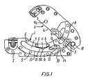
- Fig. 1 shows a hinge fitting for a pivotal window comprising a first hinge part 1 which is with a base plate 2 adapted to be secured on a not shown side member for the frame of the window, and a second hinge part 3, which is also provided with a base plate 4 to secure on a similar and not shown frame side member.
- individual parts such as the base plate 4 of the second hinge part 3, are made transparent in Fig. 1 with a view to the readability of the drawing.
- a corresponding but reverse hinge fitting is mounted on the opposite pair of frame or sash side members to determine a pivot axis essentially parallel to the top and bottom members of the frame and the sash.
- a plate piece 6 is secured by means of rivets or screws 5 and at a distance from the base plate 2 and provided with a circular slit constituting a control means or a guide 7 for a slide bar 8 essentially similar to the guide and arranged on the second hinge part 3 during a part of the opening and closing movement of the window.
- the guide 7 comprises a convex side or wall 11 and a concave side or wall 12.
- the slide bar 8 is by means of a hinge pin 9 pivotally connected with the base plate 4 of the second hinge part 3 which also has a guide pin 10, the function of which will be explained in the following.
- the convex side or wall 11 of the guide 7 comprises beside the plate piece 6 one or more lamellae placed between the plate piece 6 and the base plate 2, and which together with the plate piece forms an abutment face for the slide bar 8 and the guide pin 10.
- a spring mechanism is inserted with a leaf spring 15 which is with folded ends fastened to two rivets 5 in this side, and which is more curved than the guide 7 such that the centre portion hereof projects most in the guide and thus is situated at some distance from the convex side 11.
- the leaf spring 15 is provided with one or more arresting points, in the embodiment shown in Fig.
- the slide bar 8 can e.g. be provided with at least one corresponding groove such that the bulging portion and the groove enter into engagement with each other during the pivoting movement of the window in order to be placed in a ventilation position.
- the window sash and thus the second hinge part 3 are turned out to an opening angle of about 135° from the closing position, e.g. with a view to cleaning the outside of the window.
- the slide bar 8 is displaced at a maximum out of the guide 7, i.e. until a stop pin 13 on the slide bar has been caught in a recess 14 in the plate piece 6.
- the base plate 4 is then turned further about the hinge pin 9. when closing the window again, this base plate 4 is not turned back until the guide pin 10 has entered the guide 7 where it rests in front of the forward end of the slide bar 8.
- a driving pin 9a brings the slide bar 8 in a position on the base plate 4, which position is fixed during the remaining part of the re-closing of the window.
- the driving pin 9a can be designed as an upward bent portion of the base plate 4. In order to minimize noise, the driving pin 9a can be provided with a separate bush component in e.g.
- first and/or second hinge part are design as upward bent portions of the relevant base plate.
- the guide pin 10 and the slide bar 8 are displaced inward in the guide, where a slide block 20 with a slide face 21 is first passed, an at least one element of an engagement set on the second hinge part 3 cooperates with braking effect with the leaf spring 15 as it enters into frictional engagement herewith, the closing movement of the window frame being stopped.
- the guide pin 10 constitutes the element of the engagement set on the second hinge part 3 which enters into frictional engagement with the leaf spring 15.
- the guide pin can, however, have different forms which are described below in connection with Figs 3 and 4.
- a spring mechanism is inserted in the concave side 12 between the plate piece 6 and the base plate 2 and comprises a leaf spring 15 which is attached by the bent ends on the outermost of the rivets 5 in this side and which is less curved than the guide 7, such that the centre portion projects farthest in the guide and thus is situated at some distance from the concave side 12.
- the leaf spring 15 is provided with at least one groove 15a, 15b, preferably between two and six grooves 15a, 15b, more preferably five grooves 15a, 15b. As shown, the leaf spring 15 can e.g.
- the leaf spring 15 can be provided with such a slope groove 15b at the extremity of both ends such that the leaf spring 15 does not happen to be turned in the wrong direction at the mounting.
- the leaf spring 15 can be subjected to a coating providing or facilitating the desired properties hereof. E.g. the leaf spring 15 can be treated with Benzinal® preventing rust.
- the leaf spring 15 can also be subjected to a coating resulting in a stiffening of the leaf spring 15.
- the leaf spring 15 can be fit tightly about the rivets such that the leaf spring is not loose and thus cannot rattle.
- the grooves 15a, 15b in the leaf spring 15 can be provided in the form of an adapter unit which can be arranged on an existing leaf spring without the desired profile, e.g. without any grooves.
- the adapter unit can be provided with any desired profile such that provided with an existing leaf spring 15, it may procure a desired number of grooves 15a, 15b.
- the leaf spring 15 can be provided with zones of a material which is softer than the rest of the leaf spring 15, such that the grooves 15a, 15b are formed by the deflection and/or compression of this other material caused by the contact between the element of the engagement set entering into engagement with the leaf spring 15 and such a zone.
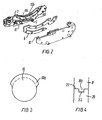
- Fig. 3 shows a first embodiment of the guide pin 10 being provided with a projecting portion 10a for improved securing of the guide pin 10 in the groove 15a.
- the projecting portion 10a extends over a part of the axial extension of the guide pin 10 such that a good engagement is secured between the guide pin 10 and the leaf spring 15 and the grooves 15a hereof, and at the same time the guide pin 10 can pass the slide block 20 and the guide 7.
- the guide pin 10 can be provided with a square pin to be mounted in the base plate 4 of the second hinge part 3, the base plate consequently being provided with a corresponding hole.
- the guide pin 10 can be produced from a material which is different from that of the remaining parts of the hinge, such as massive bronze, which makes the guide pin 10 more resistant to wear and tear.
- the guide pin 10 can be provided with a separate bush component extending over essentially the entire axial extension of the guide pin 10.
- a guide pin device can e.g. be designed in the way shown in EP 1038083 B1.
- the guide pin 10 can be provided with a separate bush component as mentioned above, where the bush component is produced from a softer material, such as plastic.
- a second embodiment of the invention is seen, where the slide bar 8 forms the element of the engagement set on the second hinge part 3 entering into frictional engagement with the leaf spring 15.
- the slide bar is provided with at least one projecting portion 8a for frictional engagement with at least one groove 15a of the leaf spring 15.
- the slide face 21 which is opposite in relation to the slide bar 8 during the pivoting movement of window is provided with a longitudinal groove 22 corresponding to the projecting portion 8a and permitting the at least one projecting portion 8a of the slide bar 8 to pass during the pivoting movement of the window.
- Fig. 3 shows the slide bar 8 with the projecting portion 8a arranged opposite the slide block 20, as seen during a part of the pivoting movement of the window.
- the longitudinal groove 22 is dimensioned such that an appropriately light passage for the at least one projecting portion 8a is present during the pivoting movement.
- the engagement with the leaf spring 15 is obtained in the way that the slide bar 8 is provided with a spring-loaded ball entering into engagement with the leaf spring 15 during at least a part of the pivoting movement.
Landscapes
- Engineering & Computer Science (AREA)
- Mechanical Engineering (AREA)
- Structural Engineering (AREA)
- Window Of Vehicle (AREA)
- Hinges (AREA)
- Wing Frames And Configurations (AREA)
- Gears, Cams (AREA)
Claims (12)
- Ferrure d'articulation destinée à une fenêtre pivotante dotée d'un cadre et d'un châssis mobile raccordé au cadre au niveau d'un axe d'articulation,
comprenant une première partie d'articulation (1) à fixer sur le cadre et une seconde partie d'articulation (3) à fixer sur le châssis mobile,
dans laquelle la première partie d'articulation (1) sur une plaque de base (2) est prévue avec des moyens de commande sous la forme d'un guide configuré en arc de cercle (7) coopérant avec un ensemble d'engagement comportant une barre de coulissement (8) essentiellement semblable au guide et montée à rotation sur une plaque de base (4) destinée à la seconde partie d'articulation (3) et une broche de guidage (10) destinée à fournir un mouvement de pivotement à la fenêtre, et
dans laquelle en liaison avec le guide (7) sur la première partie d'articulation (1), un dispositif de freinage est prévu avec un ressort à lames (15) qui, pendant au moins une partie du mouvement de pivotement, se trouve en engagement frictionnel avec au moins un élément de l'ensemble d'engagement sur la seconde partie d'articulation (3),
caractérisée en ce que le ressort à lames (15) est prévu avec au moins un point d'arrêt (15a, 15b ; 15c) pour un engagement avec au moins un élément dudit ensemble d'engagement situé sur la seconde partie d'articulation (3) pendant le mouvement de pivotement dans au moins une position intermédiaire prédéfinie. - Ferrure d'articulation selon la revendication 1, caractérisée en ce que chaque point d'arrêt comprend une gorge (15a, 15b) qui est conçue de telle sorte qu'au moins un élément dudit ensemble d'engagement est adapté pour s'y déplacer et y être retenu dans un engagement frictionnel plus assujetti dans la gorge (15a, 15b).
- Ferrure d'articulation selon la revendication 2, caractérisée en ce que la broche de guidage (10) est l'élément de l'ensemble d'engagement sur la seconde partie d'articulation (3) qui entre en engagement frictionnel avec le ressort à lames (15).
- Ferrure d'articulation selon l'une des revendications 2 et 3, caractérisée en ce que la broche de guidage (10) est, au niveau d'une section faisant face au ressort à lames prévu avec une partie en saillie (10a) pour améliorer un assujettissement de la broche de guidage (10) dans la gorge (15a, 15b).
- Ferrure d'articulation selon l'une des revendications 2 à 4, caractérisée en ce que la barre de coulissement (8) est l'élément de l'ensemble d'engagement sur la seconde partie d'articulation (3) destiné à entrer en engagement frictionnel avec le ressort à lames (15) et est prévue avec au moins une partie en saillie (8a) destinée à un engagement fictionnel avec ladite (lesdites) gorge(s) (15a, 15b) du ressort à lames (15a), et en ce que un bloc de glissière (20) est prévu avec une gorge longitudinale correspondante (20) pour le passage de la barre de coulissement (8) dotée de la partie en saillie (8a) pendant le mouvement de pivotement de la fenêtre.
- Ferrure d'articulation selon l'une des revendications 2 à 5, caractérisée en ce que la broche de guidage (10) et la barre de coulissement (8) entrent toutes les deux en engagement frictionnel avec le ressort à lames (15).
- Ferrure d'articulation selon l'une des revendications 2 à 6, caractérisée en ce qu'un élément de manchon séparé est disposé sur la broche de guidage (10).
- Ferrure d'articulation selon l'une des revendications 2 à 7, caractérisée en ce que le ressort à lames (15) est pourvu de deux à six gorges (15a, 15b) opposées au guide, de préférence de cinq gorges (15a, 15b).
- Ferrure d'articulation selon l'une des revendications 1 à 8, caractérisée en ce qu'au moins le côté du ressort à lames (15) faisant face au guide (7) est fabriqué à partir d'un matériau qui est autre par rapport à celui de l'une ou à plusieurs des parties restantes de l'articulation, et qui est, de préférence, plus souple que l'une ou que plusieurs des parties restantes de l'articulation, où le matériau est, de préférence, du plastique.
- Ferrure d'articulation selon la revendication 1, caractérisée en ce que chaque point d'arrêt comporte une partie de renflement (15c), et en ce que ledit ensemble d'engagement est prévu avec au moins une gorge correspondante.
- Fenêtre pourvue d'une ferrure d'articulation dans laquelle le châssis mobile de la fenêtre est raccordé au cadre de la fenêtre par l'intermédiaire d'un ensemble de ferrures d'articulation, et dans laquelle le positionnement de l'ensemble de ferrures d'articulation sur le châssis mobile et sur le cadre définit un axe de rotation pour la fenêtre, caractérisée en ce que ledit ensemble comprend deux ferrures d'articulation selon l'une des revendications 1 à 10.
- Utilisation d'une ferrure d'articulation selon l'une quelconque des revendications 1 à 10 dans une fenêtre dotée d'un cadre et d'un châssis mobile.
Priority Applications (24)
| Application Number | Priority Date | Filing Date | Title |
|---|---|---|---|
| DE602004003575T DE602004003575T2 (de) | 2004-07-02 | 2004-07-02 | Gelenkbeschlag für ein Drehfenster |
| ES04388045T ES2279328T3 (es) | 2004-07-02 | 2004-07-02 | Accesorio de articulacion para una ventana pivotante. |
| PL04388045T PL1612352T3 (pl) | 2004-07-02 | 2004-07-02 | Łącznik zawiasowy dla okna obrotowego |
| EP04388045A EP1612352B1 (fr) | 2004-07-02 | 2004-07-02 | Ferrure d'articulation pour une fenêtre pivotante |
| SI200430211T SI1612352T1 (sl) | 2004-07-02 | 2004-07-02 | Zgibni okov za nihajno okno |
| AT04388045T ATE347643T1 (de) | 2004-07-02 | 2004-07-02 | Gelenkbeschlag für ein drehfenster |
| EP14177003.2A EP2821575A3 (fr) | 2003-08-20 | 2004-08-19 | Fenêtre à pivot optimisée avec au moins un dispositif d'ouverture auxiliaire et un moyen de retenue |
| ES04762776T ES2289541T3 (es) | 2003-08-20 | 2004-08-19 | Una ventana basculante mejorada con medio de retencion. |
| EP04762775.7A EP1685304B1 (fr) | 2003-08-20 | 2004-08-19 | Fenêtre basculante perfectionnée equipée d'au moins un dispositif d'ouverture auxiliaire et d'un élément de retenue |
| PL04762776T PL1656489T3 (pl) | 2003-08-20 | 2004-08-19 | Ulepszone okno obrotowe ze środkiem blokującym |
| PCT/DK2004/000552 WO2005019575A1 (fr) | 2003-08-20 | 2004-08-19 | Fenetre basculante perfectionnee equipee d'un element de retenue |
| EP04762776A EP1656489B1 (fr) | 2003-08-20 | 2004-08-19 | Fenetre basculante perfectionnee equipee d'un moyen de retenue |
| CN2004800233415A CN1836084B (zh) | 2003-08-20 | 2004-08-19 | 带有至少一个辅助开启装置和阻滞装置的改进的枢转窗户 |
| CN2004800233449A CN1853025B (zh) | 2003-08-20 | 2004-08-19 | 带有阻滞装置的改进的枢转窗户 |
| PL10181028.1T PL2280143T3 (pl) | 2003-08-20 | 2004-08-19 | Ulepszone okno obrotowe z co najmniej jednym pomocniczym urządzeniem otwierającym |
| EP10181028.1A EP2280143B1 (fr) | 2003-08-20 | 2004-08-19 | Ferrure d'articulation pour une fenêtre pivotante |
| PL04762775T PL1685304T3 (pl) | 2003-08-20 | 2004-08-19 | Ulepszone okno obrotowe z co najmniej jednym pomocniczym urządzeniem otwierającym i środkami zatrzymującymi |
| EA200600437A EA007727B1 (ru) | 2003-08-20 | 2004-08-19 | Усовершенствованное поворотное окно с по меньшей мере одним вспомогательным открывающим устройством и средством фиксации |
| PCT/DK2004/000551 WO2005019574A1 (fr) | 2003-08-20 | 2004-08-19 | Fenetre basculante perfectionnee equipee d'au moins un dispositif d'ouverture auxiliaire et d'un element de retenue |
| AT04762776T ATE364768T1 (de) | 2003-08-20 | 2004-08-19 | Verbessertes kippfenster mit arretiermittel |
| DE602004007009T DE602004007009T2 (de) | 2003-08-20 | 2004-08-19 | Verbessertes kippfenster mit arretiermittel |
| CNU2004200881082U CN2734950Y (zh) | 2003-08-20 | 2004-08-20 | 带有阻滞装置的改进的枢转窗户 |
| CNU2004200881078U CN2734949Y (zh) | 2003-08-20 | 2004-08-20 | 带有辅助开启装置和阻滞装置的改进的枢转窗户 |
| CNU2005200020317U CN2795387Y (zh) | 2004-07-02 | 2005-02-01 | 用于枢转窗户的铰链装置 |
Applications Claiming Priority (1)
| Application Number | Priority Date | Filing Date | Title |
|---|---|---|---|
| EP04388045A EP1612352B1 (fr) | 2004-07-02 | 2004-07-02 | Ferrure d'articulation pour une fenêtre pivotante |
Publications (3)
| Publication Number | Publication Date |
|---|---|
| EP1612352A1 EP1612352A1 (fr) | 2006-01-04 |
| EP1612352A8 EP1612352A8 (fr) | 2006-07-19 |
| EP1612352B1 true EP1612352B1 (fr) | 2006-12-06 |
Family
ID=34931946
Family Applications (1)
| Application Number | Title | Priority Date | Filing Date |
|---|---|---|---|
| EP04388045A Expired - Lifetime EP1612352B1 (fr) | 2003-08-20 | 2004-07-02 | Ferrure d'articulation pour une fenêtre pivotante |
Country Status (7)
| Country | Link |
|---|---|
| EP (1) | EP1612352B1 (fr) |
| CN (1) | CN2795387Y (fr) |
| AT (1) | ATE347643T1 (fr) |
| DE (1) | DE602004003575T2 (fr) |
| ES (1) | ES2279328T3 (fr) |
| PL (1) | PL1612352T3 (fr) |
| SI (1) | SI1612352T1 (fr) |
Families Citing this family (7)
| Publication number | Priority date | Publication date | Assignee | Title |
|---|---|---|---|---|
| JP4833332B2 (ja) | 2006-03-27 | 2011-12-07 | ヴィーケーアール・ホールディング・アー・エス | 窓またはドアの枠内に設けられるスクリーニング装置を支持するブラケット部材、連結部材、窓またはドア、およびスクリーニング装置 |
| PL213375B1 (pl) * | 2006-07-19 | 2013-02-28 | Fakro Pp Spolka Z Ograniczona Odpowiedzialnoscia | Zawias do okna dachowego ze skrzydlem obrotowym |
| EP3486413B1 (fr) * | 2017-11-21 | 2024-01-10 | VKR Holding A/S | Charnière de pivotement ayant de meilleures propriétés de frottement |
| PL3828360T3 (pl) | 2019-11-29 | 2024-06-03 | Vkr Holding A/S | System do instalacji okna i sposób instalacji okna dachowego |
| PL3872274T3 (pl) | 2020-02-27 | 2025-06-02 | Vkr Holding A/S | System do instalacji okna i sposób instalacji okna dachowego |
| HUE067797T2 (hu) | 2020-05-29 | 2024-11-28 | Vkr Holding As | Tetõablak beépítési rendszer és eljárás tetõablak beépítésére |
| DK181529B1 (en) | 2021-07-05 | 2024-04-05 | Vkr Holding As | Handling and installation assembly |
Family Cites Families (4)
| Publication number | Priority date | Publication date | Assignee | Title |
|---|---|---|---|---|
| US2948916A (en) * | 1956-05-16 | 1960-08-16 | Atvidabergs Butiksinredningar | Pivot bearing for horizontal and vertical pivoted windows |
| DK150661C (da) * | 1983-12-15 | 1988-06-06 | Rasmussen Holding As V Kann | Haengselbeslag med fjederbremsning til vippevinduer |
| DK176024B1 (da) * | 1997-11-11 | 2005-12-19 | Vkr Holding As | Hængselbeslag til et vippevindue |
| GB9925007D0 (en) * | 1999-10-22 | 1999-12-22 | Keystone Lintels Ltd | Hinge for pivot window |
-
2004
- 2004-07-02 PL PL04388045T patent/PL1612352T3/pl unknown
- 2004-07-02 EP EP04388045A patent/EP1612352B1/fr not_active Expired - Lifetime
- 2004-07-02 DE DE602004003575T patent/DE602004003575T2/de not_active Expired - Lifetime
- 2004-07-02 ES ES04388045T patent/ES2279328T3/es not_active Expired - Lifetime
- 2004-07-02 SI SI200430211T patent/SI1612352T1/sl unknown
- 2004-07-02 AT AT04388045T patent/ATE347643T1/de not_active IP Right Cessation
-
2005
- 2005-02-01 CN CNU2005200020317U patent/CN2795387Y/zh not_active Expired - Fee Related
Also Published As
| Publication number | Publication date |
|---|---|
| DE602004003575D1 (de) | 2007-01-18 |
| ES2279328T3 (es) | 2007-08-16 |
| SI1612352T1 (sl) | 2007-06-30 |
| CN2795387Y (zh) | 2006-07-12 |
| ATE347643T1 (de) | 2006-12-15 |
| EP1612352A8 (fr) | 2006-07-19 |
| PL1612352T3 (pl) | 2007-05-31 |
| DE602004003575T2 (de) | 2007-10-11 |
| EP1612352A1 (fr) | 2006-01-04 |
Similar Documents
| Publication | Publication Date | Title |
|---|---|---|
| EP1038083B1 (fr) | Charniere pour fenetre pivotante | |
| EP1781883B1 (fr) | Ferrures d'articulation comprenant un element intermediaire, fenetre comportant de telles ferrures d'articulation et utilisation d'une telle ferrure d'articulation | |
| US7673372B2 (en) | Block and tackle balance assembly with brake shoe | |
| US20090133220A1 (en) | Hinges and Parts Therefor | |
| US7353857B2 (en) | Chain stopper | |
| US20040163213A1 (en) | Hinge | |
| US20020166207A1 (en) | Hinge with height adjustment screw | |
| EP0352912A1 (fr) | Charnière invisible à fermeture automatique avec force de fermeture sélectivement variable | |
| EP1612352A1 (fr) | Ferrure d'articulation pour une fenêtre pivotante | |
| EP3486413A1 (fr) | Charnière de pivotement ayant de meilleures propriétés de frottement | |
| EP1685304B1 (fr) | Fenêtre basculante perfectionnée equipée d'au moins un dispositif d'ouverture auxiliaire et d'un élément de retenue | |
| US7013529B2 (en) | Block and tackle sash balance brake assembly | |
| GB2182387A (en) | Window stays | |
| EP1290304B1 (fr) | Paumelle pour fenetres pivotantes | |
| EP3348763B1 (fr) | Ensemble de bras intermédiaire pour une fenêtre de toit à double fonction | |
| GB2214230A (en) | Window stays | |
| GB2221721A (en) | Improvements in or relating to stay hinges | |
| EP1391578A2 (fr) | Entrebaílleur à friction à usage intensif pour un élément d'ouverture | |
| EP1270858B1 (fr) | Gond de securite | |
| GB2416189A (en) | Stay with slidable supports and independent slidable restricting body | |
| EP2821575A2 (fr) | Fenêtre à pivot optimisée avec au moins un dispositif d'ouverture auxiliaire et un moyen de retenue | |
| HU223252B1 (hu) | Vasalat ablakokhoz és ajtókhoz | |
| AU2021362148A1 (en) | A door hinge for household appliances | |
| GB2281346A (en) | Friction stay | |
| BE1032267A1 (nl) | Beslag voor een kipbaar raam |
Legal Events
| Date | Code | Title | Description |
|---|---|---|---|
| PUAI | Public reference made under article 153(3) epc to a published international application that has entered the european phase |
Free format text: ORIGINAL CODE: 0009012 |
|
| AK | Designated contracting states |
Kind code of ref document: A1 Designated state(s): AT BE BG CH CY CZ DE DK EE ES FI FR GB GR HU IE IT LI LU MC NL PL PT RO SE SI SK TR |
|
| AX | Request for extension of the european patent |
Extension state: AL HR LT LV MK |
|
| 17P | Request for examination filed |
Effective date: 20051227 |
|
| RIN1 | Information on inventor provided before grant (corrected) |
Inventor name: JENSEN, JAN FAHLEN Inventor name: SORENSEN, PETER |
|
| GRAP | Despatch of communication of intention to grant a patent |
Free format text: ORIGINAL CODE: EPIDOSNIGR1 |
|
| RIN1 | Information on inventor provided before grant (corrected) |
Inventor name: SORENSEN, PETER Inventor name: JENSEN, JAN FAHLEN |
|
| AKX | Designation fees paid |
Designated state(s): AT BE BG CH CY CZ DE DK EE ES FI FR GB GR HU IE IT LI LU MC NL PL PT RO SE SI SK TR |
|
| GRAS | Grant fee paid |
Free format text: ORIGINAL CODE: EPIDOSNIGR3 |
|
| GRAA | (expected) grant |
Free format text: ORIGINAL CODE: 0009210 |
|
| AK | Designated contracting states |
Kind code of ref document: B1 Designated state(s): AT BE BG CH CY CZ DE DK EE ES FI FR GB GR HU IE IT LI LU MC NL PL PT RO SE SI SK TR |
|
| PG25 | Lapsed in a contracting state [announced via postgrant information from national office to epo] |
Ref country code: FI Free format text: LAPSE BECAUSE OF FAILURE TO SUBMIT A TRANSLATION OF THE DESCRIPTION OR TO PAY THE FEE WITHIN THE PRESCRIBED TIME-LIMIT Effective date: 20061206 Ref country code: RO Free format text: LAPSE BECAUSE OF FAILURE TO SUBMIT A TRANSLATION OF THE DESCRIPTION OR TO PAY THE FEE WITHIN THE PRESCRIBED TIME-LIMIT Effective date: 20061206 Ref country code: DK Free format text: LAPSE BECAUSE OF FAILURE TO SUBMIT A TRANSLATION OF THE DESCRIPTION OR TO PAY THE FEE WITHIN THE PRESCRIBED TIME-LIMIT Effective date: 20061206 |
|
| REG | Reference to a national code |
Ref country code: CH Ref legal event code: EP |
|
| REG | Reference to a national code |
Ref country code: IE Ref legal event code: FG4D |
|
| REF | Corresponds to: |
Ref document number: 602004003575 Country of ref document: DE Date of ref document: 20070118 Kind code of ref document: P |
|
| PG25 | Lapsed in a contracting state [announced via postgrant information from national office to epo] |
Ref country code: BG Free format text: LAPSE BECAUSE OF FAILURE TO SUBMIT A TRANSLATION OF THE DESCRIPTION OR TO PAY THE FEE WITHIN THE PRESCRIBED TIME-LIMIT Effective date: 20070306 Ref country code: SE Free format text: LAPSE BECAUSE OF FAILURE TO SUBMIT A TRANSLATION OF THE DESCRIPTION OR TO PAY THE FEE WITHIN THE PRESCRIBED TIME-LIMIT Effective date: 20070306 |
|
| REG | Reference to a national code |
Ref country code: CH Ref legal event code: NV Representative=s name: SUSI PRYDE-HAENI BSC |
|
| PG25 | Lapsed in a contracting state [announced via postgrant information from national office to epo] |
Ref country code: PT Free format text: LAPSE BECAUSE OF FAILURE TO SUBMIT A TRANSLATION OF THE DESCRIPTION OR TO PAY THE FEE WITHIN THE PRESCRIBED TIME-LIMIT Effective date: 20070507 |
|
| REG | Reference to a national code |
Ref country code: PL Ref legal event code: T3 |
|
| ET | Fr: translation filed | ||
| REG | Reference to a national code |
Ref country code: ES Ref legal event code: FG2A Ref document number: 2279328 Country of ref document: ES Kind code of ref document: T3 |
|
| REG | Reference to a national code |
Ref country code: HU Ref legal event code: AG4A Ref document number: E001774 Country of ref document: HU |
|
| RAP2 | Party data changed (patent owner data changed or rights of a patent transferred) |
Owner name: VKR HOLDING A/S |
|
| REG | Reference to a national code |
Ref country code: CH Ref legal event code: PFA Owner name: VKR HOLDING A/S Free format text: VKR HOLDING A/S#TOBAKSVEJEN 10#2860 SOBORG (DK) -TRANSFER TO- VKR HOLDING A/S#BREELTEVEJ 18#2970 HOERSHOLM (DK) |
|
| PLBE | No opposition filed within time limit |
Free format text: ORIGINAL CODE: 0009261 |
|
| STAA | Information on the status of an ep patent application or granted ep patent |
Free format text: STATUS: NO OPPOSITION FILED WITHIN TIME LIMIT |
|
| NLT2 | Nl: modifications (of names), taken from the european patent patent bulletin |
Owner name: VKR HOLDING A/S Effective date: 20070829 |
|
| 26N | No opposition filed |
Effective date: 20070907 |
|
| PG25 | Lapsed in a contracting state [announced via postgrant information from national office to epo] |
Ref country code: MC Free format text: LAPSE BECAUSE OF NON-PAYMENT OF DUE FEES Effective date: 20070731 Ref country code: GR Free format text: LAPSE BECAUSE OF FAILURE TO SUBMIT A TRANSLATION OF THE DESCRIPTION OR TO PAY THE FEE WITHIN THE PRESCRIBED TIME-LIMIT Effective date: 20070307 |
|
| PGFP | Annual fee paid to national office [announced via postgrant information from national office to epo] |
Ref country code: SI Payment date: 20080701 Year of fee payment: 5 |
|
| PGFP | Annual fee paid to national office [announced via postgrant information from national office to epo] |
Ref country code: SK Payment date: 20080701 Year of fee payment: 5 Ref country code: AT Payment date: 20080715 Year of fee payment: 5 Ref country code: IE Payment date: 20080728 Year of fee payment: 5 |
|
| PG25 | Lapsed in a contracting state [announced via postgrant information from national office to epo] |
Ref country code: EE Free format text: LAPSE BECAUSE OF FAILURE TO SUBMIT A TRANSLATION OF THE DESCRIPTION OR TO PAY THE FEE WITHIN THE PRESCRIBED TIME-LIMIT Effective date: 20061206 |
|
| PG25 | Lapsed in a contracting state [announced via postgrant information from national office to epo] |
Ref country code: CY Free format text: LAPSE BECAUSE OF FAILURE TO SUBMIT A TRANSLATION OF THE DESCRIPTION OR TO PAY THE FEE WITHIN THE PRESCRIBED TIME-LIMIT Effective date: 20061206 Ref country code: LU Free format text: LAPSE BECAUSE OF NON-PAYMENT OF DUE FEES Effective date: 20070702 |
|
| PG25 | Lapsed in a contracting state [announced via postgrant information from national office to epo] |
Ref country code: TR Free format text: LAPSE BECAUSE OF FAILURE TO SUBMIT A TRANSLATION OF THE DESCRIPTION OR TO PAY THE FEE WITHIN THE PRESCRIBED TIME-LIMIT Effective date: 20061206 |
|
| REG | Reference to a national code |
Ref country code: SI Ref legal event code: KO00 Effective date: 20100224 |
|
| REG | Reference to a national code |
Ref country code: SK Ref legal event code: MM4A Ref document number: E 1661 Country of ref document: SK Effective date: 20090702 |
|
| PG25 | Lapsed in a contracting state [announced via postgrant information from national office to epo] |
Ref country code: SK Free format text: LAPSE BECAUSE OF NON-PAYMENT OF DUE FEES Effective date: 20090702 Ref country code: SI Free format text: LAPSE BECAUSE OF NON-PAYMENT OF DUE FEES Effective date: 20090703 |
|
| PG25 | Lapsed in a contracting state [announced via postgrant information from national office to epo] |
Ref country code: AT Free format text: LAPSE BECAUSE OF NON-PAYMENT OF DUE FEES Effective date: 20090702 |
|
| PG25 | Lapsed in a contracting state [announced via postgrant information from national office to epo] |
Ref country code: IE Free format text: LAPSE BECAUSE OF NON-PAYMENT OF DUE FEES Effective date: 20090702 |
|
| PGFP | Annual fee paid to national office [announced via postgrant information from national office to epo] |
Ref country code: CH Payment date: 20110725 Year of fee payment: 8 |
|
| PGFP | Annual fee paid to national office [announced via postgrant information from national office to epo] |
Ref country code: CZ Payment date: 20120625 Year of fee payment: 9 |
|
| PGFP | Annual fee paid to national office [announced via postgrant information from national office to epo] |
Ref country code: ES Payment date: 20120824 Year of fee payment: 9 Ref country code: HU Payment date: 20120613 Year of fee payment: 9 |
|
| PG25 | Lapsed in a contracting state [announced via postgrant information from national office to epo] |
Ref country code: CZ Free format text: LAPSE BECAUSE OF NON-PAYMENT OF DUE FEES Effective date: 20130702 |
|
| REG | Reference to a national code |
Ref country code: CH Ref legal event code: PL |
|
| PG25 | Lapsed in a contracting state [announced via postgrant information from national office to epo] |
Ref country code: LI Free format text: LAPSE BECAUSE OF NON-PAYMENT OF DUE FEES Effective date: 20130731 Ref country code: CH Free format text: LAPSE BECAUSE OF NON-PAYMENT OF DUE FEES Effective date: 20130731 Ref country code: HU Free format text: LAPSE BECAUSE OF NON-PAYMENT OF DUE FEES Effective date: 20130703 |
|
| PGFP | Annual fee paid to national office [announced via postgrant information from national office to epo] |
Ref country code: IT Payment date: 20140711 Year of fee payment: 11 |
|
| PGFP | Annual fee paid to national office [announced via postgrant information from national office to epo] |
Ref country code: BE Payment date: 20140714 Year of fee payment: 11 |
|
| REG | Reference to a national code |
Ref country code: FR Ref legal event code: PLFP Year of fee payment: 12 |
|
| REG | Reference to a national code |
Ref country code: ES Ref legal event code: FD2A Effective date: 20150709 |
|
| PG25 | Lapsed in a contracting state [announced via postgrant information from national office to epo] |
Ref country code: ES Free format text: LAPSE BECAUSE OF NON-PAYMENT OF DUE FEES Effective date: 20130703 |
|
| PG25 | Lapsed in a contracting state [announced via postgrant information from national office to epo] |
Ref country code: IT Free format text: LAPSE BECAUSE OF NON-PAYMENT OF DUE FEES Effective date: 20150702 |
|
| REG | Reference to a national code |
Ref country code: FR Ref legal event code: PLFP Year of fee payment: 13 |
|
| PGFP | Annual fee paid to national office [announced via postgrant information from national office to epo] |
Ref country code: NL Payment date: 20160711 Year of fee payment: 13 |
|
| REG | Reference to a national code |
Ref country code: FR Ref legal event code: PLFP Year of fee payment: 14 |
|
| PG25 | Lapsed in a contracting state [announced via postgrant information from national office to epo] |
Ref country code: BE Free format text: LAPSE BECAUSE OF NON-PAYMENT OF DUE FEES Effective date: 20150731 |
|
| PGFP | Annual fee paid to national office [announced via postgrant information from national office to epo] |
Ref country code: GB Payment date: 20170628 Year of fee payment: 14 Ref country code: FR Payment date: 20170623 Year of fee payment: 14 |
|
| REG | Reference to a national code |
Ref country code: NL Ref legal event code: MM Effective date: 20170801 |
|
| PG25 | Lapsed in a contracting state [announced via postgrant information from national office to epo] |
Ref country code: NL Free format text: LAPSE BECAUSE OF NON-PAYMENT OF DUE FEES Effective date: 20170801 |
|
| PGFP | Annual fee paid to national office [announced via postgrant information from national office to epo] |
Ref country code: PL Payment date: 20180613 Year of fee payment: 15 |
|
| GBPC | Gb: european patent ceased through non-payment of renewal fee |
Effective date: 20180702 |
|
| PG25 | Lapsed in a contracting state [announced via postgrant information from national office to epo] |
Ref country code: GB Free format text: LAPSE BECAUSE OF NON-PAYMENT OF DUE FEES Effective date: 20180702 Ref country code: FR Free format text: LAPSE BECAUSE OF NON-PAYMENT OF DUE FEES Effective date: 20180731 |
|
| PGFP | Annual fee paid to national office [announced via postgrant information from national office to epo] |
Ref country code: DE Payment date: 20190618 Year of fee payment: 16 |
|
| REG | Reference to a national code |
Ref country code: DE Ref legal event code: R119 Ref document number: 602004003575 Country of ref document: DE |
|
| PG25 | Lapsed in a contracting state [announced via postgrant information from national office to epo] |
Ref country code: PL Free format text: LAPSE BECAUSE OF NON-PAYMENT OF DUE FEES Effective date: 20190702 Ref country code: DE Free format text: LAPSE BECAUSE OF NON-PAYMENT OF DUE FEES Effective date: 20210202 |