EP1612753A2 - Bestandteil, der eine Diebstahlsicherungsvorrichtung enthält - Google Patents
Bestandteil, der eine Diebstahlsicherungsvorrichtung enthält Download PDFInfo
- Publication number
- EP1612753A2 EP1612753A2 EP05013847A EP05013847A EP1612753A2 EP 1612753 A2 EP1612753 A2 EP 1612753A2 EP 05013847 A EP05013847 A EP 05013847A EP 05013847 A EP05013847 A EP 05013847A EP 1612753 A2 EP1612753 A2 EP 1612753A2
- Authority
- EP
- European Patent Office
- Prior art keywords
- cavity
- theft device
- electronic article
- article
- label
- Prior art date
- Legal status (The legal status is an assumption and is not a legal conclusion. Google has not performed a legal analysis and makes no representation as to the accuracy of the status listed.)
- Withdrawn
Links
Images

Classifications
-
- G—PHYSICS
- G08—SIGNALLING
- G08B—SIGNALLING SYSTEMS, e.g. PERSONAL CALLING SYSTEMS; ORDER TELEGRAPHS; ALARM SYSTEMS
- G08B13/00—Burglar, theft or intruder alarms
- G08B13/22—Electrical actuation
- G08B13/24—Electrical actuation by interference with electromagnetic field distribution
- G08B13/2402—Electronic Article Surveillance [EAS], i.e. systems using tags for detecting removal of a tagged item from a secure area, e.g. tags for detecting shoplifting
- G08B13/2428—Tag details
- G08B13/2437—Tag layered structure, processes for making layered tags
- G08B13/2445—Tag integrated into item to be protected, e.g. source tagging
Definitions
- the present invention relates to electronic articles containing anti-theft devices and to methods for deterring the theft of electronic articles and for preventing the deactivation of anti-theft devices associated with electronic articles by magnetic or electromagnetic fields generated by the motor in the article.
- Anti-theft devices such as security tags or electronic article surveillance systems are used for inventory control and for preventing unauthorized removal of articles from a controlled area.
- such systems include a transmitter and a receiver that are used to establish a surveillance zone, which must be traversed by any articles being removed from the controlled area.
- the transmitting and receiving antennas are typically mounted in floors, walls, and ceilings or may be in the form of freestanding pylons.
- the anti-theft device such as a security tag
- Certain types of security tags are designed to be disposable and are generally not removable to the point of sale. Therefore, the security tag must be deactivated before the article containing the security tag is removed from the security area. Deactivation may be accomplished by equipment that changes an electromagnetic or magnetic characteristic of the security tag so that the security tag is no longer detectable at the surveillance zone. These types of security tags may, however, cover important information printed on the article's packaging and present an appearance that is not aesthetically pleasing. Furthermore, such tags may be subject to tampering by consumers or other individuals not authorized to remove the devices.
- Prior attempts to alleviate this problem include housing a security tag in a one or two piece cylinder that is snapped together to form a permanent mechanical seal around a power cord, rather than attaching the security tag directly to the body of the article containing a motor.
- This attempted solution results in a conspicuous security tag that is cumbersome in the use of the article. Further, positioning the security tag in this manner increases manufacturing costs without contributing to the functionality or aesthetics of the product.
- One aspect of the present invention is directed to an electronic article containing a cavity, an anti-theft device placed inside the cavity, and a covering placed over the cavity.
- the cavity is located on a component remote from the motor of the electronic article and is covered with an adhesive label, which may be temporary or permanent.
- Incorporating the anti-theft device into a portion of an electronic article, such as a power tool, in this manner has the advantages of: (a) decreasing the potential for tampering with the anti-theft device, (b) increasing the aesthetics of the external packaging, (c) minimizing the risk that the anti-theft device will be deactivated by exposure to a magnetic field created by the motor in the article, (d) allowing removal of the anti-theft device without disassembly of the article, and (e) providing a simple and inexpensive technique for bringing any electronic article into compliance with the certification programs required by many retail facilities (e.g., the requirement that the anti-theft device be located within three inches of the UPC bar code), without requiring a hollow area in the design of the article large enough to house an anti-theft device (the cavity may be created just below the surface of the article).
- the electronic article of the present invention not only deters theft, but also increases the efficiency of the retail facility by allowing the anti-theft device to be placed in close proximity to the UPC bar code, thereby allowing nearly simultaneous deactivation of the anti-theft device and scanning of the bar code at the point of sale.
- Another aspect of the present invention is directed to a method for deterring the theft of an electronic article, such as a power tool.
- the method includes inserting an anti-theft device into a cavity located in the electronic article and placing a covering over the cavity.
- the cavity may be placed on a component remote from the motor in the electronic article, thereby reducing the risk that the anti-theft device will be deactivated by the running of the motor.
- the cavity is covered with an adhesive label, such as a label containing safety information, brand information, or bar code information.
- Yet another aspect of the present invention is directed to a method for preventing the deactivation of an anti-theft device by a magnetic or electromagnetic field generated by an article containing a motor.
- the method includes placing an anti-theft device inside a cavity of an electronic article and covering the cavity with, for example, an adhesive label.
- the cavity is located on a component remote from the motor.
- Figure 1 shows one embodiment of the present invention in which an anti-theft device is housed behind a label and within a cavity in a plastic component of a power tool.
- Figure 2 shows the embodiment depicted in Figure 1 with the label partially removed to reveal the anti-theft device in the cavity.
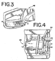
- Figure 3 shows another embodiment of the present invention in which an anti-theft device is housed in a cavity in a power tool handle and covered with a label.
- Figure 4 shows yet another embodiment of the present invention in which an anti-theft device is housed in a cavity in a chain brake for a chainsaw, remote from the motor but in close proximity to a bar code label placed on the packaging.
- One embodiment of the present invention includes an anti-theft device 14 disposed within a cavity 16 in a portion 10, desirably a plastic component, of a power tool.
- the anti-theft device 14 is disposed entirely within the cavity 16.
- the cavity 16 may be covered with a label 12, as shown in Figures 1 and 2.
- the component 10 in which the anti-theft device 14 is housed is located remote from the motor 20 of the power tool 28, as shown in Figures 3 and 4.
- the anti-theft device 14 may be placed loosely within the cavity 16 or may be secured within the cavity 16 in any suitable and known manner.
- the anti-theft device 14 may have one surface containing an adhesive that allows the anti-theft device 14 to be securely attached to an inner surface of the cavity 16.
- the anti-theft device 14 may be secured to an outer surface of a component of the article or secured to or within the packaging of the article.
- One type of anti-theft device 14 is in the form of a security tag that contains a magnetic sensor assembly that includes a magneto-mechanical active element that mechanically vibrates to generate a detectable signal at the frequency of an applied interrogation signal.
- Another type of security tag contains a magnetic sensor assembly that includes a soft magnetic active element that generates a detectable signal at a harmonic of the frequency of the applied interrogation signal.
- the magnetic sensor element also includes a hard or semi-hard magnetic biasing element. By changing the magnetic state of this biasing element, the active element of the tag is enabled or disabled from generating the detectable signal, thereby activating or deactivating the tag.
- the biasing element is magnetized along its longer length dimension by a permanent magnet to activate the tag.
- a permanent magnet By either degaussing the biasing element along its length or by magnetizing it along its shorter width dimension, the tag is deactivated.
- the tag In a harmonic tag, when the biasing element is demagnetized, the tag is activated. By magnetizing the biasing element along its longer length dimension, the tag is then deactivated. Degaussing the biasing element along its length then activates the tag again.
- Suitable anti-theft devices in the form of a security tag are available from SENSORMATIC ELECTRONICS CORPORATION, Boca Raton, FL.
- the anti-theft device 14 is located in a cavity 16 behind a label 12 on a plastic component 10 of a power tool. More particularly, in the embodiments shown in Figures 3 and 4, the anti-theft device is located in a cavity behind a label 12 on the handle 18 of a power tool 28 and on a chain brake 22 for a chainsaw, respectively. Locating the anti-theft device 14 in this manner maximizes the distance between the anti-theft device 14 and the motor 20 of the power tool 28, thereby decreasing the likelihood that the anti-theft device 14 will be deactivated by a magnetic or electromagnetic field generated by the motor 20 of the power tool 28.
- any suitable and known material may be used as a covering.
- the covering may be made from a hook-and-loop fastener material (as disclosed in U.S. Patent No. 5,802,676 and sold under the trademark VELCRO) that may be secured around the edges of the cavity.
- VELCRO trademark of Lucent Technologies Inc.
- Such material may also be used to secure the anti-theft device within the cavity so that, if desired, the user of the article may remove the anti-theft device after purchase and use the cavity to store small components, for example.
- the covering may be secured to the cavity in a readily releasable manner, such as by use of a rigid material configured to slide back and forth over the cavity or a flexible material secured to the cavity with snaps, buttons, buckles, ties, clasps, hooks, or the like.
- the power tool 28 containing the anti-theft device 14 and label 12 may be placed in a package 26 for distribution to retailers, distributors, and/ or consumers.
- the power tool 28 is shown as a chainsaw, but it may be any power tool or other electronic article.
- a bar code label 24 is attached to the package 26 in close proximity to the anti-theft device in the cavity covered by the label 12. This arrangement increases the efficiency of the retail facility by allowing nearly simultaneous deactivation of the anti-theft device and scanning of the bar code at the point of sale.
- the article After assembly of an electronic article such as a power tool is complete, the article is often subjected to quality assurance tests. During these tests, the article may be placed into operation, thereby generating a magnetic or electromagnetic field. These fields may decrease the effectiveness of any anti-theft device contained within the article or may entirely deactivate the anti-theft device. Once the anti-theft device becomes deactivated, it will no longer be sensed by the detection equipment and, therefore, will no longer serve its function of preventing theft of the article.
- the present invention contemplates a method for preventing such deactivation, including packaging the electronic article with the anti-theft device positioned to maximize the distance between the anti-theft device and the motor inside the article. This method minimizes the exposure of the anti-theft device to any magnetic field generated by a permanent magnet inside the motor or any electromagnetic field generated by a wound field motor.
- a method for deterring the theft of an electronic article such as a power tool, includes inserting an anti-theft device into a cavity located in the electronic article and covering the cavity.
- the covering may be made of any suitable and known material and may be secured over the cavity in any suitable and known manner.
- the covering may be a label adhesively secured over the cavity or a flexible material secured over the cavity with snaps, buttons, buckles, stitches, ties, adhesive, screws, bolts, staples, clasps, hooks, or the like.
- the method includes locating the cavity on a component of the electronic article remote from the motor in the article. This configuration decreases the probability of deactivation of the anti-theft device by the running of the motor during quality assurance testing, for example.
- the method is performed in reverse order to detach the covering from the article and remove the anti-theft device from the cavity.
- the cavity may then be used as a storage compartment.
- the covering is fastened over the cavity in such a way that the user may easily detach and re-attach the covering to access the items stored within the cavity.
- the method includes packaging the electronic article for distribution to consumers, distributors, and/or retailers.
- a bar code label may then be placed on the package.
- the method of the present invention allows the bar code label to be placed within about three inches of the anti-theft device, as required by many retailers, to facilitate simultaneous deactivation of the anti-theft device and scanning of the bar code label.
- an authorized individual may deactivate the anti-theft device.
- Deactivation devices typically use coils that are energized to generate a magnetic field of sufficient magnitude to render the anti-theft device inactive. The deactivated devices are no longer responsive to the incident energy of the electronic article surveillance system, and therefore, an alarm is not triggered. Examples of deactivation devices are set forth in U.S. Patent No. 6,084,514.
Landscapes
- Physics & Mathematics (AREA)
- Engineering & Computer Science (AREA)
- Automation & Control Theory (AREA)
- Computer Security & Cryptography (AREA)
- Electromagnetism (AREA)
- General Physics & Mathematics (AREA)
- Burglar Alarm Systems (AREA)
Applications Claiming Priority (1)
| Application Number | Priority Date | Filing Date | Title |
|---|---|---|---|
| US58372504P | 2004-06-28 | 2004-06-28 |
Publications (2)
| Publication Number | Publication Date |
|---|---|
| EP1612753A2 true EP1612753A2 (de) | 2006-01-04 |
| EP1612753A3 EP1612753A3 (de) | 2007-11-14 |
Family
ID=34982573
Family Applications (1)
| Application Number | Title | Priority Date | Filing Date |
|---|---|---|---|
| EP05013847A Withdrawn EP1612753A3 (de) | 2004-06-28 | 2005-06-27 | Bestandteil, der eine Diebstahlsicherungsvorrichtung enthält |
Country Status (2)
| Country | Link |
|---|---|
| EP (1) | EP1612753A3 (de) |
| AU (1) | AU2005202836A1 (de) |
Cited By (1)
| Publication number | Priority date | Publication date | Assignee | Title |
|---|---|---|---|---|
| CN112081476A (zh) * | 2020-10-15 | 2020-12-15 | 杭州申迪电子科技有限公司 | 一种新型挂钩防盗标签的锁芯结构 |
Family Cites Families (5)
| Publication number | Priority date | Publication date | Assignee | Title |
|---|---|---|---|---|
| US5499015A (en) * | 1994-09-28 | 1996-03-12 | Sensormatic Electronics Corp. | Magnetomechanical EAS components integrated with a retail product or product packaging |
| US5847650A (en) * | 1996-10-04 | 1998-12-08 | Knogo North America Inc. | Theft resistant circuit assembly |
| CA2283552A1 (en) * | 1999-09-10 | 2001-03-10 | Jean-Guy St. Pierre | Activation code and ownership identification system for power tools |
| DE10029133A1 (de) * | 2000-06-14 | 2002-01-03 | Hilti Ag | Elektrohandwerkzeuggerät mit Werkzeug |
| DE10260706C5 (de) * | 2002-12-23 | 2019-03-14 | Hilti Aktiengesellschaft | Transponderaufnahme |
-
2005
- 2005-06-27 EP EP05013847A patent/EP1612753A3/de not_active Withdrawn
- 2005-06-28 AU AU2005202836A patent/AU2005202836A1/en not_active Abandoned
Cited By (1)
| Publication number | Priority date | Publication date | Assignee | Title |
|---|---|---|---|---|
| CN112081476A (zh) * | 2020-10-15 | 2020-12-15 | 杭州申迪电子科技有限公司 | 一种新型挂钩防盗标签的锁芯结构 |
Also Published As
| Publication number | Publication date |
|---|---|
| EP1612753A3 (de) | 2007-11-14 |
| AU2005202836A1 (en) | 2006-01-12 |
Similar Documents
| Publication | Publication Date | Title |
|---|---|---|
| US8451128B2 (en) | Asset protection system | |
| US8334776B2 (en) | Electronic article surveillance carrier and tag | |
| US8421628B2 (en) | Asset protection system | |
| EP0704828B1 (de) | Magnetomechanische, in Waren oder Warenverpackung integrierte EAS-Komponenten | |
| US6472989B2 (en) | Child protection bracelet | |
| US8878675B2 (en) | Merchandise tags with removal detection for theft prevention | |
| US6199309B1 (en) | Merchandising markers accomodating anti-theft sensor | |
| US5714935A (en) | Article of merchandise with concealed EAS marker and EAS warning logo | |
| WO2010147915A1 (en) | Multiple technology eas tag and system | |
| US20050200485A1 (en) | Article containing anti-theft device | |
| AU737687B2 (en) | Article of merchandise with EAS marker and associated indicia | |
| US20140043163A1 (en) | Asset protection system | |
| US20100213263A1 (en) | Electronic Article Surveillance Tag Assembly | |
| US6573835B2 (en) | Child monitoring device | |
| AU2008306441B2 (en) | Surveillance device | |
| US6352606B1 (en) | Consumer article security arrangement | |
| EP1612753A2 (de) | Bestandteil, der eine Diebstahlsicherungsvorrichtung enthält | |
| US8286881B2 (en) | Secure battery compartment for alarming hard tag | |
| US20220049539A1 (en) | Anti-theft gate system | |
| AU718179B2 (en) | Magnetomechanical EAS components integrated with a retail product or product packaging | |
| WO2021130491A1 (en) | Security tag | |
| CA2347333A1 (en) | Electromagnetic anti-shoplifting system |
Legal Events
| Date | Code | Title | Description |
|---|---|---|---|
| PUAI | Public reference made under article 153(3) epc to a published international application that has entered the european phase |
Free format text: ORIGINAL CODE: 0009012 |
|
| AK | Designated contracting states |
Kind code of ref document: A2 Designated state(s): AT BE BG CH CY CZ DE DK EE ES FI FR GB GR HU IE IS IT LI LT LU MC NL PL PT RO SE SI SK TR |
|
| AX | Request for extension of the european patent |
Extension state: AL BA HR LV MK YU |
|
| PUAL | Search report despatched |
Free format text: ORIGINAL CODE: 0009013 |
|
| AK | Designated contracting states |
Kind code of ref document: A3 Designated state(s): AT BE BG CH CY CZ DE DK EE ES FI FR GB GR HU IE IS IT LI LT LU MC NL PL PT RO SE SI SK TR |
|
| AX | Request for extension of the european patent |
Extension state: AL BA HR LV MK YU |
|
| AKX | Designation fees paid | ||
| STAA | Information on the status of an ep patent application or granted ep patent |
Free format text: STATUS: THE APPLICATION IS DEEMED TO BE WITHDRAWN |
|
| 18D | Application deemed to be withdrawn |
Effective date: 20080515 |
|
| REG | Reference to a national code |
Ref country code: DE Ref legal event code: 8566 |