EP1613093A2 - Présentation de budget binaire selon des régions des images comprimées - Google Patents
Présentation de budget binaire selon des régions des images comprimées Download PDFInfo
- Publication number
- EP1613093A2 EP1613093A2 EP05254007A EP05254007A EP1613093A2 EP 1613093 A2 EP1613093 A2 EP 1613093A2 EP 05254007 A EP05254007 A EP 05254007A EP 05254007 A EP05254007 A EP 05254007A EP 1613093 A2 EP1613093 A2 EP 1613093A2
- Authority
- EP
- European Patent Office
- Prior art keywords
- block
- bit
- video
- color
- video signal
- Prior art date
- Legal status (The legal status is an assumption and is not a legal conclusion. Google has not performed a legal analysis and makes no representation as to the accuracy of the status listed.)
- Withdrawn
Links
- 238000007906 compression Methods 0.000 claims description 14
- 230000006835 compression Effects 0.000 claims description 13
- 238000012544 monitoring process Methods 0.000 claims 1
- 238000011156 evaluation Methods 0.000 description 7
- 239000003086 colorant Substances 0.000 description 4
- 238000010586 diagram Methods 0.000 description 4
- 230000005540 biological transmission Effects 0.000 description 3
- 210000003746 feather Anatomy 0.000 description 3
- 238000012360 testing method Methods 0.000 description 3
- 241000023320 Luma <angiosperm> Species 0.000 description 2
- 230000015556 catabolic process Effects 0.000 description 2
- 230000007423 decrease Effects 0.000 description 2
- 238000006731 degradation reaction Methods 0.000 description 2
- 230000000694 effects Effects 0.000 description 2
- 238000001914 filtration Methods 0.000 description 2
- 238000013507 mapping Methods 0.000 description 2
- 238000000034 method Methods 0.000 description 2
- OSWPMRLSEDHDFF-UHFFFAOYSA-N methyl salicylate Chemical compound COC(=O)C1=CC=CC=C1O OSWPMRLSEDHDFF-UHFFFAOYSA-N 0.000 description 2
- 230000009467 reduction Effects 0.000 description 2
- 241001270131 Agaricus moelleri Species 0.000 description 1
- 238000013459 approach Methods 0.000 description 1
- 230000008859 change Effects 0.000 description 1
- 239000002131 composite material Substances 0.000 description 1
- 230000006870 function Effects 0.000 description 1
- 230000008569 process Effects 0.000 description 1
- 238000012545 processing Methods 0.000 description 1
- 230000003252 repetitive effect Effects 0.000 description 1
- 239000013598 vector Substances 0.000 description 1
Images


Classifications
-
- H—ELECTRICITY
- H04—ELECTRIC COMMUNICATION TECHNIQUE
- H04N—PICTORIAL COMMUNICATION, e.g. TELEVISION
- H04N19/00—Methods or arrangements for coding, decoding, compressing or decompressing digital video signals
- H04N19/10—Methods or arrangements for coding, decoding, compressing or decompressing digital video signals using adaptive coding
- H04N19/134—Methods or arrangements for coding, decoding, compressing or decompressing digital video signals using adaptive coding characterised by the element, parameter or criterion affecting or controlling the adaptive coding
- H04N19/146—Data rate or code amount at the encoder output
-
- H—ELECTRICITY
- H04—ELECTRIC COMMUNICATION TECHNIQUE
- H04N—PICTORIAL COMMUNICATION, e.g. TELEVISION
- H04N19/00—Methods or arrangements for coding, decoding, compressing or decompressing digital video signals
- H04N19/10—Methods or arrangements for coding, decoding, compressing or decompressing digital video signals using adaptive coding
- H04N19/169—Methods or arrangements for coding, decoding, compressing or decompressing digital video signals using adaptive coding characterised by the coding unit, i.e. the structural portion or semantic portion of the video signal being the object or the subject of the adaptive coding
- H04N19/17—Methods or arrangements for coding, decoding, compressing or decompressing digital video signals using adaptive coding characterised by the coding unit, i.e. the structural portion or semantic portion of the video signal being the object or the subject of the adaptive coding the unit being an image region, e.g. an object
- H04N19/172—Methods or arrangements for coding, decoding, compressing or decompressing digital video signals using adaptive coding characterised by the coding unit, i.e. the structural portion or semantic portion of the video signal being the object or the subject of the adaptive coding the unit being an image region, e.g. an object the region being a picture, frame or field
-
- H—ELECTRICITY
- H04—ELECTRIC COMMUNICATION TECHNIQUE
- H04N—PICTORIAL COMMUNICATION, e.g. TELEVISION
- H04N19/00—Methods or arrangements for coding, decoding, compressing or decompressing digital video signals
- H04N19/10—Methods or arrangements for coding, decoding, compressing or decompressing digital video signals using adaptive coding
- H04N19/169—Methods or arrangements for coding, decoding, compressing or decompressing digital video signals using adaptive coding characterised by the coding unit, i.e. the structural portion or semantic portion of the video signal being the object or the subject of the adaptive coding
- H04N19/17—Methods or arrangements for coding, decoding, compressing or decompressing digital video signals using adaptive coding characterised by the coding unit, i.e. the structural portion or semantic portion of the video signal being the object or the subject of the adaptive coding the unit being an image region, e.g. an object
- H04N19/176—Methods or arrangements for coding, decoding, compressing or decompressing digital video signals using adaptive coding characterised by the coding unit, i.e. the structural portion or semantic portion of the video signal being the object or the subject of the adaptive coding the unit being an image region, e.g. an object the region being a block, e.g. a macroblock
-
- H—ELECTRICITY
- H04—ELECTRIC COMMUNICATION TECHNIQUE
- H04N—PICTORIAL COMMUNICATION, e.g. TELEVISION
- H04N19/00—Methods or arrangements for coding, decoding, compressing or decompressing digital video signals
- H04N19/60—Methods or arrangements for coding, decoding, compressing or decompressing digital video signals using transform coding
- H04N19/61—Methods or arrangements for coding, decoding, compressing or decompressing digital video signals using transform coding in combination with predictive coding
-
- H—ELECTRICITY
- H04—ELECTRIC COMMUNICATION TECHNIQUE
- H04N—PICTORIAL COMMUNICATION, e.g. TELEVISION
- H04N19/00—Methods or arrangements for coding, decoding, compressing or decompressing digital video signals
- H04N19/70—Methods or arrangements for coding, decoding, compressing or decompressing digital video signals characterised by syntax aspects related to video coding, e.g. related to compression standards
Definitions
- the present invention relates to image compression, and more particularly to an area mapped compressed image bit budget monitor that may be used to artistically optimize an image for a given file size or transmission bit rate.
- An image such as a frame of a video signal, is compressed to either fit into a smaller file size or to reduce the bit rate during transmission of the video signal.
- lossy compression there is a greater reduction in file size or bit rate, but there is also some degradation of image quality when decompressed.
- Modern video image compressors do a very good job, but there is always the need to shrink the file size or to send more video streams through the same bit rate pipe. This pushes the limits of the compressors. Artists generally have always had to deal with the limits of their media. For example, video has always had a limited dynamic range between the lightest and the darkest areas of a particular scene that can be depicted.
- a video artist, or videographer uses a waveform monitor to help adjust the lighting on the scene to make the best use of that dynamic range. He might let some of the areas be overexposed or underexposed if they are not important to the scene, but the important parts are set to be within the limited dynamic range.
- the compression of a video signal gives a new set of limitations on the content to get it successfully into a certain file size or to achieve a desired transmission bit rate.
- the tools for maximizing quality or minimizing bit rates are very limited. Quality maximization or bit rate reduction is usually done by experimentation.
- the videographer may use an MPEG analyzer to obtain requisite information by inspecting block information, but this is time consuming and therefore not suited for artistic work.
- the videographer inputs the video signal to be compressed into a compressor, decompresses the output from the compressor and examines the output on an evaluation monitor display.
- An unsophisticated videographer may use just this output as is, even if the videographer is not satisfied with the outcome.
- a sophisticated videographer may use the knowledge of the video compression process to make a "guess” as to what is causing the problem and go back and make adjustments to the input video, and then rerun the test. The adjustment and test sequence is repeated until the videographer is satisfied. Since the adjustments are based on "guesses", the procedure is not very efficient and the results may be far from optimal.
- What is desired is a system that enables a videographer to optimally maximize video picture quality while minimizing the bit rate or file size required.
- the present invention provides an area mapped compressed image bit budget monitor for a compressed video signal that represents frames of a video signal broken down into blocks of pixels with each block being represented by a bit sequence.
- the bits in each bit sequence are counted to produce bit counts that are translated into color and intensity values.
- the color and intensity values are used to present an area mapped display, with each block of a displayed frame being outlined according to the associated color and intensity value, or the outline being alternatively filled by the associated color and intensity value.
- the area mapped display may also include a cursor in the form of a filled or "flat" block together with an associated coefficient array for the block indicated by the cursor.
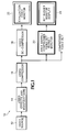
- a video compression quality chain 10 having a video source 12 containing video to be compressed.
- the video from the video source 12 is input to a video effects and modulation stage 14 where a videographer manipulates or adjusts the video to produce a desired output video.
- the desired output video is input to a standard video compressor 16 to provide a compressed video output.
- the compressed video output also is input to a standard video de-compressor 18 to recover a degraded version of the desired output video for display on an evaluation monitor display 20 . So far what has been described is a standard video compression quality chain where the videographer according to the prior art uses "guesses" in a repetitive adjustment and test sequence while observing the evaluation monitor display 20 until the video images are satisfactory.
- the present invention adds to the standard video compression video quality train an area mapped compressed image bit budget monitor 22 for processing the compressed video output, with the results being displayed on a bit budget monitor display 24 .
- the bit budget monitor 22 shows on the related monitor 24 the relative bit usage of various areas in the video image, thus giving the videographer insight into what areas of the video image are using up the bit budget in order to allow the videographer to make better "guesses” and use fewer iterations to approach an optimal solution faster.
- the video compressor 16 the video is broken down into frames or individual images, and the images are broken down into blocks of picture elements or pixels. These blocks of pixels are analyzed and a bit sequence is encoded for each block of pixels, typically using a discrete cosine transform (DCT) function with the resulting coefficients being quantized and processed by a variable length encoder (VLE).
- DCT discrete cosine transform
- VLE variable length encoder
- the bit sequence has a lot of information, such as motion vectors for moving picture images such as in the video signal, but the bit sequence is an encoding of the block of pixels.
- the bit budget monitor 22 counts the number of bits that encode each block of pixels and shows them to the videographer as an area mapped display on the bit budget monitor display 24.
- Fig. 2 shows a frame from the video as it appears on the evaluation monitor display 20
- Fig. 3 shows the same frame as it appears on the bit budget monitor display 24 .
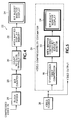
- the compressed video output is input to a block parser 26 for determining the bit sequences for each block of each frame in the compressed video output.
- Each bit sequence from the block parser 26 is input to a bit counter 28 where the number of bits for each block of pixels is counted.
- the bit count for each block from the bit counter 28 is input to a translator to map the bit count into an understandable form, such as a color and intensity.
- the colors and intensities are stored in an area mapped display memory 30 and then presented to the videographer in a corresponding area of the display 24 as the block of the frame from which it was derived.
- the number of bits encoding a particular block has been converted into a color and intensity that outlines that block.
- Each block is framed by its own color and intensity one pixel wide so shared boundaries show information from both adjacent blocks.
- the videographer then easily sees which areas of the picture are using the most bits. To point out the value of this information, note that in Fig. 3 the areas corresponding to the feather in the hat use far more bits, as shown by the red outlines, than the face which is probably more important artistically. Other forms than those depicted in Fig. 3 may be used, such as gray scales or displays where whole blocks are covered by the color and intensity.
- Gray scales or displays where whole blocks are covered by the color and intensity.
- Relative scales as well as absolute scales may be used.
- An absolute scale depiction for different file sizes by the same compressor 16 indicates the actual bit usage for each setting and so is different for each setting.
- a relative scale depiction indicates the relative bit usage in various areas of the video frame or image, and shows whether or not it is changed by the different compressor settings.
- the relative bit usage for an image may change little with different compressor settings, while the absolute bit usage changes a lot, indicating that the relative bit usage isn't being affected. In either case it is apparent that more bit usage is greater in one portion of the image than in another.
- the bit usage may or may not be what the videographer intends.
- the videographer for the image of Fig. 3 may desire more bits to go to the face as opposed to the feather since the face is artistically more important.
- a video compressibility estimator 34 is shown in Fig. 5.
- the video from a video source, such as a camera 36 is input to the standard video compressor 16 and the bit sequences for the blocks of pixels are input to the bit budget monitor 22 for presentation on the bit budget monitor display 24 .
- Such a video compressibility estimator 34 would normally be used where video is being made that is intended for subsequent compression and the videographer desires to make it as compressible as possible.
- the videographer may ask the model to remove the feather.
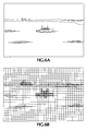
- a picture of a ship is shown as it might appear on the evaluation monitor display 20 (Fig. 6A) and on the bit budget monitor display 24 (Fig. 6B) including a scale that correlates the block outline colors to a range of bits per block.
- the evaluation monitor display 20 Fig. 6A
- the bit budget monitor display 24 Fig. 6B
- a scale that correlates the block outline colors to a range of bits per block.
- bit budget monitor 24 may be applied to just the luma component or just the chroma component. It quickly becomes apparent that most of the bits are used for luma and not for chroma, so the problem will not be solved by adjusting colors or chroma information.
- a cursor 38 shown as a grey or "flat" block on the display, and a corresponding DCT coefficient array 40 for that block may be displayed, as shown in Fig. 7.
- the DCT coefficient usage for each area is discernible.
- the videographer may see that the sea is using more DCT coefficients than the sky, and so may decide to use a spatial filter on the sea to cut down its bit usage since it isn't that artistically important.
- Fig. 8 shows the same boat scene with a demarcation line 42 that divides the scene into a region for spatial filtering (most of the sea) and a region that is not spatial filtered.
- the spatial filter may be implemented by zeroing out all coefficients, depicted as black in Fig. 9, except those in the first row and first column that are depicted as grey. This may not be optimum, but it serves for the present example because it is easy to see that this significantly decreases the information content from the sea when compared with the coefficient array 40 shown in Fig. 7. As a result the sea portion of the image may be degraded, but it is still artistically acceptable. In this particular example for a JPEG image file the original picture image may be reduced from 29K bytes to 19K bytes. If the same spatial filter is applied to the entire image, then there is severe degradation in artistic quality throughout the image, which is not acceptable. Thus the bit budget monitor enables the videographer to make the correct choices for spatial filtering.
- the present area mapped bit usage display may also be used with non-block coded compressors, such as wavelet compressors or zip compressors.
- the compression scheme is one called LZW, which is a dictionary based compression scheme.
- LZW is a dictionary based compression scheme.
- An image file to be compressed is scanned and a dictionary is generated where codes represent strings in the input file that are repeated elsewhere in the file.
- the compressed data stream consists entirely of codes that identify the strings. If the codes plus the dictionary are smaller than the original file, then the file has been compressed.
- the compressed .GIF file 40 is input to a dictionary extractor 42 and a dictionary 44 .
- Output from the dictionary 44 are decoded data that produces a decoded image 46 and code bit counts and block assignments, where the image space is divided up into blocks. Each block is assigned a separate block accumulator 48 . This is more arbitrary that in the block coded compression schemes, but a suitable block size may be selected.
- the compressed bit stream 40 is read and decompressed, i.e., the codes are read and looked up in the dictionary 44 , the number of bits used in each code read is added to the accumulator 48 for the block where the data being decoded will go.
- the accumulated block counts are sent to the count to color translator 30 , and then to the area mapped display memory 32 together with the decoded image 46 . The result is displayed on the bit budget monitor display 24 .
- the present invention provides an array mapped compressed image bit budget monitor that counts the bits of each bit sequence of a compressed image representing a block of pixels from an image, and presents the resulting bit usage information on a suitable display using color and intensity values or grey scale values for each block in the image.
Landscapes
- Engineering & Computer Science (AREA)
- Multimedia (AREA)
- Signal Processing (AREA)
- Compression Or Coding Systems Of Tv Signals (AREA)
- Compression Of Band Width Or Redundancy In Fax (AREA)
- Image Generation (AREA)
Applications Claiming Priority (1)
| Application Number | Priority Date | Filing Date | Title |
|---|---|---|---|
| US10/882,006 US20050286785A1 (en) | 2004-06-29 | 2004-06-29 | Area mapped compressed image bit budget monitor |
Publications (2)
| Publication Number | Publication Date |
|---|---|
| EP1613093A2 true EP1613093A2 (fr) | 2006-01-04 |
| EP1613093A3 EP1613093A3 (fr) | 2008-12-24 |
Family
ID=35134397
Family Applications (1)
| Application Number | Title | Priority Date | Filing Date |
|---|---|---|---|
| EP05254007A Withdrawn EP1613093A3 (fr) | 2004-06-29 | 2005-06-28 | Présentation de budget binaire selon des régions des images comprimées |
Country Status (3)
| Country | Link |
|---|---|
| US (1) | US20050286785A1 (fr) |
| EP (1) | EP1613093A3 (fr) |
| JP (1) | JP4708882B2 (fr) |
Cited By (1)
| Publication number | Priority date | Publication date | Assignee | Title |
|---|---|---|---|---|
| TWI382766B (zh) * | 2008-12-23 | 2013-01-11 | Nat Univ Tsing Hua | 一種用於超高解析度之顯示框壓縮系統及方法 |
Families Citing this family (2)
| Publication number | Priority date | Publication date | Assignee | Title |
|---|---|---|---|---|
| JP4775202B2 (ja) * | 2006-09-15 | 2011-09-21 | ソニー株式会社 | 表示制御装置、表示制御方法、およびプログラム |
| CN104660905B (zh) * | 2015-03-04 | 2018-03-16 | 广东欧珀移动通信有限公司 | 拍照处理方法及装置 |
Citations (1)
| Publication number | Priority date | Publication date | Assignee | Title |
|---|---|---|---|---|
| EP0869684A2 (fr) * | 1997-04-04 | 1998-10-07 | Hewlett-Packard Company | Analyseur de la qualité d'un train numérique |
Family Cites Families (7)
| Publication number | Priority date | Publication date | Assignee | Title |
|---|---|---|---|---|
| US5138303A (en) * | 1989-10-31 | 1992-08-11 | Microsoft Corporation | Method and apparatus for displaying color on a computer output device using dithering techniques |
| US5239625A (en) * | 1991-03-05 | 1993-08-24 | Rampage Systems, Inc. | Apparatus and method to merge images rasterized at different resolutions |
| JPH05176173A (ja) * | 1991-12-20 | 1993-07-13 | Dainippon Screen Mfg Co Ltd | 画像データ圧縮方法 |
| JPH06334988A (ja) * | 1993-05-26 | 1994-12-02 | Hitachi Ltd | 圧縮画像評価方法および画像データ圧縮表示装置 |
| US6320986B1 (en) * | 1995-08-18 | 2001-11-20 | International Business Machines Corporation | Preprocessing multiple bit per pixel sampled data for Lempel-Ziv compression |
| JPH10117346A (ja) * | 1996-10-11 | 1998-05-06 | Xing:Kk | 情報供給装置、情報再生装置及び情報供給再生システム |
| JP3733083B2 (ja) * | 2002-05-08 | 2006-01-11 | 日本放送協会 | 映像品質評価支援装置、及び映像品質評価支援プログラム |
-
2004
- 2004-06-29 US US10/882,006 patent/US20050286785A1/en not_active Abandoned
-
2005
- 2005-06-28 JP JP2005188882A patent/JP4708882B2/ja not_active Expired - Fee Related
- 2005-06-28 EP EP05254007A patent/EP1613093A3/fr not_active Withdrawn
Patent Citations (1)
| Publication number | Priority date | Publication date | Assignee | Title |
|---|---|---|---|---|
| EP0869684A2 (fr) * | 1997-04-04 | 1998-10-07 | Hewlett-Packard Company | Analyseur de la qualité d'un train numérique |
Cited By (1)
| Publication number | Priority date | Publication date | Assignee | Title |
|---|---|---|---|---|
| TWI382766B (zh) * | 2008-12-23 | 2013-01-11 | Nat Univ Tsing Hua | 一種用於超高解析度之顯示框壓縮系統及方法 |
Also Published As
| Publication number | Publication date |
|---|---|
| US20050286785A1 (en) | 2005-12-29 |
| JP4708882B2 (ja) | 2011-06-22 |
| JP2006020311A (ja) | 2006-01-19 |
| EP1613093A3 (fr) | 2008-12-24 |
Similar Documents
| Publication | Publication Date | Title |
|---|---|---|
| US6244514B1 (en) | Smart card for storage and retrieval of digitally compressed color images | |
| US10165297B2 (en) | High dynamic range codecs | |
| US9232226B2 (en) | Systems and methods for perceptually lossless video compression | |
| US6356588B1 (en) | Method for digital compression of color images | |
| EP1285399B1 (fr) | Compression amelioree d'images a niveaux de gris | |
| EP3697073B1 (fr) | Procédés et appareil de traitement d'images utilisant des définitions de gamme de couleurs localisée | |
| EP0974933A2 (fr) | Compression video adaptative par quantification variable | |
| KR100782818B1 (ko) | Yuv에서 rgb로 휘도 보존 컬러 변환 방법 및 시스템 | |
| US20070053429A1 (en) | Color video codec method and system | |
| EP1324618A2 (fr) | Méthode et dispositif pour le codage | |
| KR20080075090A (ko) | 이미지 개선 및 압축 | |
| EP1613093A2 (fr) | Présentation de budget binaire selon des régions des images comprimées | |
| US6687412B1 (en) | Method and system for generating image compression quantization matrices | |
| JP2001197318A (ja) | カラーイメージのデジタル圧縮方法 | |
| US20090202165A1 (en) | Image decoding method and image decoding apparatus | |
| HK40036367B (en) | Image processing methods and apparatus using localized gamut definitions | |
| Larabi et al. | Psychovisual evaluation of the effect of color spaces and color quantification in JPEG2000 image compression | |
| HK40036367A (en) | Image processing methods and apparatus using localized gamut definitions | |
| JPH06152971A (ja) | 画像データ符号化方法及び装置 | |
| HK1037764A (en) | Method for digital compression of color images |
Legal Events
| Date | Code | Title | Description |
|---|---|---|---|
| PUAI | Public reference made under article 153(3) epc to a published international application that has entered the european phase |
Free format text: ORIGINAL CODE: 0009012 |
|
| AK | Designated contracting states |
Kind code of ref document: A2 Designated state(s): AT BE BG CH CY CZ DE DK EE ES FI FR GB GR HU IE IS IT LI LT LU MC NL PL PT RO SE SI SK TR |
|
| AX | Request for extension of the european patent |
Extension state: AL BA HR LV MK YU |
|
| PUAL | Search report despatched |
Free format text: ORIGINAL CODE: 0009013 |
|
| AK | Designated contracting states |
Kind code of ref document: A3 Designated state(s): AT BE BG CH CY CZ DE DK EE ES FI FR GB GR HU IE IS IT LI LT LU MC NL PL PT RO SE SI SK TR |
|
| AX | Request for extension of the european patent |
Extension state: AL BA HR LV MK YU |
|
| RIC1 | Information provided on ipc code assigned before grant |
Ipc: H04N 7/50 20060101ALI20081119BHEP Ipc: H04N 7/30 20060101ALI20081119BHEP Ipc: H04N 7/26 20060101AFI20051102BHEP |
|
| 17P | Request for examination filed |
Effective date: 20090624 |
|
| AKX | Designation fees paid |
Designated state(s): AT BE BG CH CY CZ DE DK EE ES FI FR GB GR HU IE IS IT LI LT LU MC NL PL PT RO SE SI SK TR |
|
| 17Q | First examination report despatched |
Effective date: 20111223 |
|
| RAP1 | Party data changed (applicant data changed or rights of an application transferred) |
Owner name: TEKTRONIX, INC. |
|
| STAA | Information on the status of an ep patent application or granted ep patent |
Free format text: STATUS: THE APPLICATION IS DEEMED TO BE WITHDRAWN |
|
| 18D | Application deemed to be withdrawn |
Effective date: 20160615 |