EP1613435B1 - Buses - Google Patents
Buses Download PDFInfo
- Publication number
- EP1613435B1 EP1613435B1 EP04716187A EP04716187A EP1613435B1 EP 1613435 B1 EP1613435 B1 EP 1613435B1 EP 04716187 A EP04716187 A EP 04716187A EP 04716187 A EP04716187 A EP 04716187A EP 1613435 B1 EP1613435 B1 EP 1613435B1
- Authority
- EP
- European Patent Office
- Prior art keywords
- nozzle
- water
- aperture
- jet
- snowmaking
- Prior art date
- Legal status (The legal status is an assumption and is not a legal conclusion. Google has not performed a legal analysis and makes no representation as to the accuracy of the status listed.)
- Expired - Lifetime
Links
- 239000007921 spray Substances 0.000 claims abstract description 21
- 239000012530 fluid Substances 0.000 claims abstract description 20
- XLYOFNOQVPJJNP-UHFFFAOYSA-N water Substances O XLYOFNOQVPJJNP-UHFFFAOYSA-N 0.000 claims description 152
- 230000007423 decrease Effects 0.000 claims description 8
- 238000006073 displacement reaction Methods 0.000 claims description 8
- 239000003570 air Substances 0.000 description 75
- 238000010899 nucleation Methods 0.000 description 30
- 230000006911 nucleation Effects 0.000 description 29
- 239000000203 mixture Substances 0.000 description 15
- 239000002245 particle Substances 0.000 description 15
- 239000012080 ambient air Substances 0.000 description 13
- 239000013078 crystal Substances 0.000 description 12
- 230000007246 mechanism Effects 0.000 description 10
- 238000000034 method Methods 0.000 description 10
- 230000000694 effects Effects 0.000 description 7
- 210000001161 mammalian embryo Anatomy 0.000 description 7
- 238000000429 assembly Methods 0.000 description 6
- 230000000712 assembly Effects 0.000 description 6
- 230000008014 freezing Effects 0.000 description 6
- 238000007710 freezing Methods 0.000 description 6
- 239000007789 gas Substances 0.000 description 6
- 238000001816 cooling Methods 0.000 description 5
- 230000003247 decreasing effect Effects 0.000 description 5
- 239000007788 liquid Substances 0.000 description 5
- 230000008569 process Effects 0.000 description 5
- 238000005507 spraying Methods 0.000 description 5
- 230000008020 evaporation Effects 0.000 description 4
- 238000001704 evaporation Methods 0.000 description 4
- 238000004519 manufacturing process Methods 0.000 description 4
- 239000000463 material Substances 0.000 description 4
- 239000007787 solid Substances 0.000 description 4
- 230000008901 benefit Effects 0.000 description 3
- 238000006243 chemical reaction Methods 0.000 description 3
- 239000004411 aluminium Substances 0.000 description 2
- XAGFODPZIPBFFR-UHFFFAOYSA-N aluminium Chemical compound [Al] XAGFODPZIPBFFR-UHFFFAOYSA-N 0.000 description 2
- 229910052782 aluminium Inorganic materials 0.000 description 2
- 238000000889 atomisation Methods 0.000 description 2
- 230000008859 change Effects 0.000 description 2
- 230000001105 regulatory effect Effects 0.000 description 2
- 239000000126 substance Substances 0.000 description 2
- JKFYKCYQEWQPTM-UHFFFAOYSA-N 2-azaniumyl-2-(4-fluorophenyl)acetate Chemical compound OC(=O)C(N)C1=CC=C(F)C=C1 JKFYKCYQEWQPTM-UHFFFAOYSA-N 0.000 description 1
- OYPRJOBELJOOCE-UHFFFAOYSA-N Calcium Chemical compound [Ca] OYPRJOBELJOOCE-UHFFFAOYSA-N 0.000 description 1
- CURLTUGMZLYLDI-UHFFFAOYSA-N Carbon dioxide Chemical compound O=C=O CURLTUGMZLYLDI-UHFFFAOYSA-N 0.000 description 1
- FYYHWMGAXLPEAU-UHFFFAOYSA-N Magnesium Chemical compound [Mg] FYYHWMGAXLPEAU-UHFFFAOYSA-N 0.000 description 1
- 229910021612 Silver iodide Inorganic materials 0.000 description 1
- 239000000654 additive Substances 0.000 description 1
- 230000000996 additive effect Effects 0.000 description 1
- 238000007664 blowing Methods 0.000 description 1
- 229910052791 calcium Inorganic materials 0.000 description 1
- 239000011575 calcium Substances 0.000 description 1
- 235000011089 carbon dioxide Nutrition 0.000 description 1
- 238000004140 cleaning Methods 0.000 description 1
- 230000008878 coupling Effects 0.000 description 1
- 238000010168 coupling process Methods 0.000 description 1
- 238000005859 coupling reaction Methods 0.000 description 1
- 238000009826 distribution Methods 0.000 description 1
- 239000000428 dust Substances 0.000 description 1
- 210000002257 embryonic structure Anatomy 0.000 description 1
- 238000005516 engineering process Methods 0.000 description 1
- 238000001125 extrusion Methods 0.000 description 1
- 239000010419 fine particle Substances 0.000 description 1
- 230000003370 grooming effect Effects 0.000 description 1
- 239000012585 homogenous medium Substances 0.000 description 1
- 230000003993 interaction Effects 0.000 description 1
- 238000003973 irrigation Methods 0.000 description 1
- 230000002262 irrigation Effects 0.000 description 1
- 238000009533 lab test Methods 0.000 description 1
- 229910052749 magnesium Inorganic materials 0.000 description 1
- 239000011777 magnesium Substances 0.000 description 1
- 238000002156 mixing Methods 0.000 description 1
- 239000008239 natural water Substances 0.000 description 1
- 238000010422 painting Methods 0.000 description 1
- 230000001737 promoting effect Effects 0.000 description 1
- 102000004169 proteins and genes Human genes 0.000 description 1
- 108090000623 proteins and genes Proteins 0.000 description 1
- 229940045105 silver iodide Drugs 0.000 description 1
- 239000005436 troposphere Substances 0.000 description 1
- 238000004804 winding Methods 0.000 description 1
Images


Classifications
-
- B—PERFORMING OPERATIONS; TRANSPORTING
- B05—SPRAYING OR ATOMISING IN GENERAL; APPLYING FLUENT MATERIALS TO SURFACES, IN GENERAL
- B05B—SPRAYING APPARATUS; ATOMISING APPARATUS; NOZZLES
- B05B1/00—Nozzles, spray heads or other outlets, with or without auxiliary devices such as valves, heating means
- B05B1/02—Nozzles, spray heads or other outlets, with or without auxiliary devices such as valves, heating means designed to produce a jet, spray, or other discharge of particular shape or nature, e.g. in single drops, or having an outlet of particular shape
- B05B1/04—Nozzles, spray heads or other outlets, with or without auxiliary devices such as valves, heating means designed to produce a jet, spray, or other discharge of particular shape or nature, e.g. in single drops, or having an outlet of particular shape in flat form, e.g. fan-like, sheet-like
- B05B1/046—Outlets formed, e.g. cut, in the circumference of tubular or spherical elements
-
- B—PERFORMING OPERATIONS; TRANSPORTING
- B05—SPRAYING OR ATOMISING IN GENERAL; APPLYING FLUENT MATERIALS TO SURFACES, IN GENERAL
- B05B—SPRAYING APPARATUS; ATOMISING APPARATUS; NOZZLES
- B05B1/00—Nozzles, spray heads or other outlets, with or without auxiliary devices such as valves, heating means
- B05B1/30—Nozzles, spray heads or other outlets, with or without auxiliary devices such as valves, heating means designed to control volume of flow, e.g. with adjustable passages
-
- B—PERFORMING OPERATIONS; TRANSPORTING
- B05—SPRAYING OR ATOMISING IN GENERAL; APPLYING FLUENT MATERIALS TO SURFACES, IN GENERAL
- B05B—SPRAYING APPARATUS; ATOMISING APPARATUS; NOZZLES
- B05B15/00—Details of spraying plant or spraying apparatus not otherwise provided for; Accessories
- B05B15/60—Arrangements for mounting, supporting or holding spraying apparatus
- B05B15/62—Arrangements for supporting spraying apparatus, e.g. suction cups
-
- B—PERFORMING OPERATIONS; TRANSPORTING
- B05—SPRAYING OR ATOMISING IN GENERAL; APPLYING FLUENT MATERIALS TO SURFACES, IN GENERAL
- B05B—SPRAYING APPARATUS; ATOMISING APPARATUS; NOZZLES
- B05B7/00—Spraying apparatus for discharge of liquids or other fluent materials from two or more sources, e.g. of liquid and air, of powder and gas
- B05B7/02—Spray pistols; Apparatus for discharge
- B05B7/08—Spray pistols; Apparatus for discharge with separate outlet orifices, e.g. to form parallel jets, i.e. the axis of the jets being parallel, to form intersecting jets, i.e. the axis of the jets converging but not necessarily intersecting at a point
- B05B7/0807—Spray pistols; Apparatus for discharge with separate outlet orifices, e.g. to form parallel jets, i.e. the axis of the jets being parallel, to form intersecting jets, i.e. the axis of the jets converging but not necessarily intersecting at a point to form intersecting jets
-
- F—MECHANICAL ENGINEERING; LIGHTING; HEATING; WEAPONS; BLASTING
- F25—REFRIGERATION OR COOLING; COMBINED HEATING AND REFRIGERATION SYSTEMS; HEAT PUMP SYSTEMS; MANUFACTURE OR STORAGE OF ICE; LIQUEFACTION SOLIDIFICATION OF GASES
- F25C—PRODUCING, WORKING OR HANDLING ICE
- F25C3/00—Processes or apparatus specially adapted for producing ice or snow for winter sports or similar recreational purposes, e.g. for sporting installations; Producing artificial snow
- F25C3/04—Processes or apparatus specially adapted for producing ice or snow for winter sports or similar recreational purposes, e.g. for sporting installations; Producing artificial snow for sledging or ski trails; Producing artificial snow
-
- B—PERFORMING OPERATIONS; TRANSPORTING
- B05—SPRAYING OR ATOMISING IN GENERAL; APPLYING FLUENT MATERIALS TO SURFACES, IN GENERAL
- B05B—SPRAYING APPARATUS; ATOMISING APPARATUS; NOZZLES
- B05B15/00—Details of spraying plant or spraying apparatus not otherwise provided for; Accessories
- B05B15/60—Arrangements for mounting, supporting or holding spraying apparatus
- B05B15/62—Arrangements for supporting spraying apparatus, e.g. suction cups
- B05B15/622—Arrangements for supporting spraying apparatus, e.g. suction cups ground-penetrating
-
- F—MECHANICAL ENGINEERING; LIGHTING; HEATING; WEAPONS; BLASTING
- F25—REFRIGERATION OR COOLING; COMBINED HEATING AND REFRIGERATION SYSTEMS; HEAT PUMP SYSTEMS; MANUFACTURE OR STORAGE OF ICE; LIQUEFACTION SOLIDIFICATION OF GASES
- F25C—PRODUCING, WORKING OR HANDLING ICE
- F25C2303/00—Special arrangements or features for producing ice or snow for winter sports or similar recreational purposes, e.g. for sporting installations; Special arrangements or features for producing artificial snow
- F25C2303/048—Snow making by using means for spraying water
- F25C2303/0481—Snow making by using means for spraying water with the use of compressed air
Definitions
- This invention relates to nozzles and more particularly to flat jet nozzles especially, but not exclusively, for use in snowmaking equipment.
- the invention also relates to snowmaking equipment.
- Nozzles There are many types, designs and configurations of nozzles that are particularly used in industrial situations for the spraying of fluids. Nozzles of this kind are used in the irrigation, cleaning, painting and fire extinguishing industries. Spraying systems incorporating nozzles of this kind have wide ranging industrial applications. Nozzles are also used in snowmaking equipment and the nozzle that is the subject of this invention has its primary use in snowmaking equipment.
- Flat jet nozzles that produce a flat spray pattern are known. They distribute liquid as a flat or sheet type spray. Some use elliptical orifices with the axis of the spray pattern being a continuation of the axis of the inlet pipe connection. Others use a deflector, the deflecting surface diverting the spray pattern away from the axis of the inlet pipe connection. There are a number of different nozzles that provide a flat spray pattern. Variations of these nozzles provide considerable variations in the spray pattern. The adjustability of nozzles of this kind is usually confined to variation in the liquid pressure.
- US 5,090,619 discloses an apparatus including a nozzle according to the pre-characterizing portion of claim 1.
- a nozzle characterized according to claim 1.
- a tube supporting axially displaceable pins is adapted to move across the aperture to decrease or increase the cross section of the aperture.
- means is provided to control the axial displacement of the pins.
- the nozzle comprises a T-piece, the leg of which is a pipe defining a fluid passageway and the head of the T being a pipe positioned across the end of the fluid passageway, an aperture is positioned in the head of the T-piece axially aligned with the fluid passageway, and a pin terminating in a planar face is positioned at each end of the head of the T--piece to be displaceable along the T-piece so that the end faces of the pin can move across the aperture to vary the cross section of the aperture.
- the fluid passageway and cross member are circular and the diameter of the fluid passageway is the same as the diameter of the cross member. It is also preferable that in adjusting the cross section of the aperture the pins move the same distance in opposing directions.
- snowmaking equipment comprising at least one flat jet water nozzle according to the invention inclined upwardly to, in use, project a plume of water droplets, the nozzle being positioned adjacent a jet of compressed air, the nozzle having an outlet aperture, and means to vary the cross section of the aperture to adjust the characteristics of the plume to suit the ambient conditions.
- the jet of compressed air is placed downstream of the nozzle.
- the jet of compressed air preferably comprises an array of apertures. The width of which equates to the width of the plume at the air jet.
- four flat jet water nozzles are positioned spaced apart in a horizontal plane, the spacing of the nozzles equating to the maximum width of each plume.
- snowmaking equipment comprising a rotatable mast that supports a head, the head comprising at least two spaced apart flat jet water nozzles according to the invention, each nozzle having an outlet aperture, each nozzle being positioned adjacent a jet of compressed air and means to vary the cross section of each aperture to vary the output of each nozzle.
- the head is vertically adjustable whilst maintaining the angle of inclination of water and air nozzles.
- the plume of water droplets escaping from each nozzle is directed tangentially against the underside of the air jet.
- the air jet preferably has an array of a plurality of spaced outlet apertures, the width of the array being substantially the same as the width of the plume at the air jet.
- the head includes four nozzles spaced so that the plumes meet at their widest points.
- the preferred embodiments that are illustrated in the accompanying drawings relate to snowmaking equipment that incorporates an adjustable flat jet nozzle.
- the invention covers both the nozzle per se applicable to many spraying industries as well as snowmaking equipment that incorporates a nozzle, it is however understood that the snowmaking equipment has many other features that contribute to its improved design and operation.
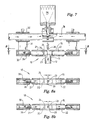
- the nozzle 10 is shown in detail in Figures 7 and 8 . Although it is shown in association with snowmaking equipment it is understood that this nozzle is applicable to many fields totally unrelated to snowmaking. The nozzle has applicability in any industrial spraying application where there is a need for a variable flat jet nozzle.
- an adjustable nozzle 10 comprises a T-piece 11, the leg 12 of which is a cylindrical fluid passageway that is secured to a rectangular mounting plate 13.
- a piece of cylindrical pipe 15 with a circular outlet aperture 20 positioned co-axially with the axis of the fluid passageway.
- the pipe 15 is hollow to accommodate a pair of cylindrical pins 21, 22.
- Each pin is cylindrical and terminates in a planar face 23 at one end.
- An O-ring 24 is located in a groove 25 on the exterior of the pin spaced from but close to the face 23.
- the other end of the pin is provided with an external thread 26 that is arranged to be a screw fit within a threaded sleeve 30 which is in turn welded to a radial flange 31 that joins a larger hollow sleeve 32 that operates as a pin guide.
- the circular cross section of the T-piece head 15 provides two converging surfaces 3 and 4 that cause water flowing towards the aperture 20 to converge towards the aperture.
- the planar ends 23 of the pins 21, 22 operate to vary the cross section of the aperture 20. As the pins move in the pipe the ends progressively close off the aperture 20 as shown in Figures 8a and 8b .
- T-piece head (not shown) could be of triangular cross section with opposed sides converging towards the aperture.
- a square tube with the aperture in one corner also provides the two converging walls.
- the head could be a rectangular block with an elongate groove with an aperture in the base of the groove.
- the pins are in block form to slide in the groove.
- the adjacent end of the pins are bevelled to define converging surfaces with the straight edges of the pins being adjacent the aperture to define an adjustable slit across the aperture.
- the nozzle described above provides a flat spray profile.
- the exact profile varies in dependence with the position of the pins 21, 22 in the aperture 20.
- Displacement of the pin guides 32 causes displacement of the pins 21, 22 to vary the cross section of the aperture 20.
- the pin guides are coupled to a suitable servo mechanism the nozzle can have a constantly variable output depending on the position of the pins. Ideally, each pin moves by the same amount in opposite directions.
- the nozzle has the advantage that its output can be varied whilst maintaining full input fluid pressure. This differs from most flat jet nozzles where the adjustability is either by variation of the input fluid pressure or by changing the nozzle aperture by replacing the end of the nozzle.
- the outlet aperture 20 of the nozzle is circular, it is understood that other shapes are envisaged.
- a larger diameter aperture provides a small spray angle whilst a smaller aperture diameter increases the spray angle.
- a wide slot provides a very wide spray angle.
- the fluid flow can be increased by increasing the width of the aperture 20 by moving the pins apart 21, 22. Conversely, a decrease in fluid flow is achieved by moving the pins 21, 22 together.
- the pressure always remains constant, namely at its maximum. Use at maximum pressure results in higher velocity and smaller spray particle size. The closer the pins are together results in small spray particles and less fluid flow which is ideal for snowmaking.
- variable flat nozzle 10 is specifically designed for use with snowmaking equipment, it is understood that this nozzle could be used in a wide range of other industrial applications.
- the adjustability of the nozzle could be manual through use of a spanner, Allen key or similar such tool to displace the pins or through more automated means by driving the pin guides as shown in Figure 7 .
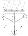
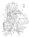
- FIGs 1 to 11 illustrate snowmaking equipment S utilising a bank of four nozzles 10 of the kind described above. As shown in Figure 3 , the nozzles 10 are mounted spaced apart so that the plumes of water particles that are ejected from the nozzles meet at their maximum width.
- the snowmaking equipment S comprises a mast M that is pivotally rotated about an adjustable base structure B that comprises three legs 51, 52, 53 mounted on adjustable skids 55 that extend outwardly by about 2 metres and are equally spaced around a common pitch circle.
- the legs 51, 52, 53 support an adjustable triangular bracing structure 60 on which the mast M is rotatably mounted.
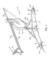
- the mast comprises a vertical column 61 that is mounted centrally of the base structure B, the vertical column 61 has a rearwardly trailing arm 62 that terminates in a mounting bracket 63 that in turn pivotally supports two closely spaced parallelogram linkages 64, 65.
- the parallelogram linkages 64, 65 pivotally supports a head assembly H that is in the form of a pair of triangular support frames 66, 67 that are rigidly secured to the spray head H.
- the spray head H is shown in Figure 5 and essentially comprises an elongate water pipe 71 referred to as a manifold that has projecting therefrom four adjustable nozzle assemblies 10 of the kind described above and shown in Figures 7 to 9 .
- Each nozzle 10 is also associated with a compressed air jet 75 as shown in Figure 5 .
- the jets 75 are interconnected by pipe 76 and fed by a common source of compressed air.
- the array of nozzles 10 and air jets 75 support a rectangular wind vane 74 shown in Figures 1 and 3 .
- the compressed air and water are supplied to the head H by flexible pipes that run down the mast M to the ground as shown in Figure 4 .
- the parallelogram linkages 64, 65 are in a parallel closely spaced configuration.
- Each parallelogram linkages 64, 65 as shown in Figure 4 comprises two elongate arms 68, 69 that are pivoted at one end to the mounting bracket 63 on the mast M and the triangular frame 66 or 67 on the spray head H at the other end.
- the parallelogram linkage has the opportunity of assuming a variety of vertical positions as shown in Figure 2 . At the highest position the arms 68, 69 extend vertically whilst at a lowest position the arms 68, 69 are slightly extended below the horizontal. In each case the triangular support for the jet assemblies remains at the same angle to the horizontal.
- the triangular frames 66, 67 can be covered in sheet material to act as a subsidiary wind vane to the primary vane 74.
- the parallelogram linkages are attached to trailing arm 80 that is coupled to a spring 81 that is in turn attached to rearwardly extending flange 82 on the base of the mast M.
- the spring 81 acts to urge the parallelogram linkages 64, 65 to assume the vertical position and the lower positions are caused by wind impinging on the vane 74 to deflect the assembly down against the spring.
- the spring could be adjustable and it is further understood that other mechanisms such as pneumatic or hydraulic dampers could replace the spring.
- the maximum height of the assembly S is approximately 6 metres.
- the spray head H incorporates four adjustable flat nozzles, each associated with a compresses air jet.
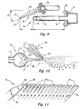
- the association of each adjustable flat nozzle 10 with the compressed air is illustrated in Figures 9 to 11 .
- the air jet 75 is in the form of a tapered jet body 76 of triangular cross section that is inclined downwardly from the horizontal by 21°.
- the jet body 75 terminates in a plurality, preferably between three and fourteen small apertures 77.
- each aperture 77 has a trailing scalloped groove 78 that is cut out of the underside of the air jet and the arrangement of the water jets 10 is such that, as shown in Figure 10 , the water first hits the underside of the air jet 75 as it tangentially passes the ends of the air jets and the apertures 77.
- the holes 77 in the end 79 of the tapered nozzle body are drilled so that they extend to the bottom surface to merge with the trailing scalloped grooves 78.
- the thin edge that is defined at the top of the apertures reduces the surface area for ice to adhere. Furthermore, the velocity of the water plume P, as it passes the apertures, clears the ice away.
- FIGs 6a to 6c illustrates the adjustability of the air nozzle 75 and water jets 10.
- the air tube 76 is mounted on a elongate shaft 101 that is axially displaceable about a sleeve 102 that is held to a support bracket via a screw 103.
- the jets 75 are in turn mounted to the shaft to be rotatable about a substantially horizontally axis as shown in Figures 6a and 6c .
- the jets 75 can also be inclined relative to the air tube 76 through a flange bracket assembly 105 shown in Figure 6c .
- the position of the water jets and water supply arm are substantially fixed to the support bracket as shown in Figures 6a, 6b and 6c .
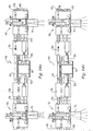
- the adjustment of the nozzle orifice size is carried out by displacement of the pins 21, 22. As shown in Figures 7 and 8 .
- the pin support sleeves 30 are connected to slides 32 via webs 39. The slides are positioned co-axial of the air pipe 76 and, as shown in Figure 7a , each sleeve 32 is arranged to be a sliding fit on the air pipe 76. All the left hand sleeves 30 of the adjustable nozzles 10 are connected to a first elongate rod 90 and all the right hand sleeves 30 are connected to a second elongate rod 91.
- the rods 90 and 91 are bolted to the respective sleeves 32 so that displacement of the rods 90, 91 has the effect of moving the sleeves 32 to in turn move the pins 21 or 22 in and out of the aperture 20 of each nozzle 10.
- the rods 90 and 91 are coupled to threaded bosses 97, 98 that support externally threaded rods 92, 93 that extend from opposite sides of a bevel gear 94.
- the bevel gear 94 meshes with a second bevel gear 95 connected to a shaft 96 that extends down the mast so that it can be driven from the base of the mast.
- rotation of the shaft 96 imparts rotation to the two rods 92, 93 extending from the beveled gear 94.
- the two shafts 92, 93 have opposite threads so that the left hand shaft has a left hand thread that has the effect of moving the boss 97 to displace the first rod 90 in one direction and the right hand shaft 93 has a right hand thread to move the boss 98 to displace the rod 91 in the opposite direction.
- fine tuning of the position of the pins 21, 22 can be done by adjusting the threaded end 26 of the pins in their sleeve by use of an Allen key.
- Figures 12 to 16 illustrate a second embodiment of a head 110 for use with snow making equipment. It is understood that the head would be supported by a mast assembly of the kind described earlier.
- the head 110 comprises four spray head assemblies 111-114 mounted across a main beam 115 that is in the form of a substantially rectangular aluminium extrusion.
- the main beam 115 provides a firm base for each spray head assembly 111-114 and also supports a centrally positioned wind mechanism 120 that facilitates the adjustment of the flat water jet nozzles 10.
- a pair of elongate drive rails 116, 117 that are also extruded in aluminium are positioned in a parallel array direction behind the main beam 115 to be driven by the wind mechanism 120 to in turn move the adjustment pins 21, 22 of the nozzles 10.
- the wind mechanism 120 is positioned centrally of the beam 115 and the four nozzle assemblies 111-114 are positioned equally spaced along the beam 115.
- the winder mechanism 120 which is shown in greater detail in Figure 15 comprises a winding shaft (not shown) that comes up from beneath the head.
- the shaft enters a wind block 121 and through bevelled gears (not shown) drives two co-axially extending shafts 123, 124 that project from either side of the wind block parallel to the rails.
- the gears provide a 7:1 ratio to introduce fine control and a mechanical advantage.
- Each shaft is in turn threadedly engaged with a drive block 125, 126 that is secured to a rectangular bracket 130, 131 that is a sliding fit on the main beam 115.
- Each block 125, 126 is reverse threaded so that rotation of the shafts 123, 124 in the same direction imparts linear movement of the blocks 125, 126 and a sliding movement of the brackets 130, 131 in opposed directions.
- Each bracket 130, 131 is in turn bolted to different drive rails so that, as shown in Figure 5 , the left hand bracket 130 drives the outer rail 117 and the right hand bracket 131 drives the inner rail 116. In this way rotation of the shaft that comes into the base of the mast has the effect of displacing the drive rails 116, 117 in opposite directions.
- the nozzle assembly 111 includes a fixed central bracket 140 that is bolted to the main beam 115.
- the central bracket 140 has a rear face 141 that is in turn welded to a flange 142 and a pair of upstanding columns 143, 144 that engage a nozzle arm support 150.
- the central bracket 140 also supports a water jet body 145 that is in the form of a rectangular block.
- the water jet body 145 includes a water inlet passage 146 coming from a water inlet pipe 147 and a head passage 148 in the manner of the earlier embodiments.
- the head passage 148 supports two adjustment pins 21, 22 that are axially displaceable across an outlet aperture 20 in a similar manner to the earlier embodiments.
- the end of each pin 21, 22 is bolted to a flange 152, 153 that is in turn supported by a pin drive 154, 155 that surrounds the main beam 115 to be slidable thereon.
- the pin drives 154, 155 are also secured to flanges 156, 157 that are respectively bolted to the drive rails 116, 117 so that movement of that drive rails imparts movement to the pin drives.
- the air nozzle 75 is coupled through a nozzle arm 160 into the nozzle arm support 150 to be coupled to an air supply pipe 161.
- the nozzle arm support 150 is adjustable vertically through a nut 163 that engages the column 143, horizontally through a screw threaded coupling 164 along the length of the arm and rotationally through two different planes due to a pivotal linkage 165 of the air nozzle to the arm.
- This universal adjustability allows fine tuning between the relationship of the air nozzle 75 and the flat jet water nozzle 10. The relationship is the same as described earlier in the specification.
- FIG. 14a and 14b illustrate the drive to displace the pins towards one another in Figure 14A and away from one another in 14b.
- the assembly has the advantage that the use of square tubing provides positive guidance to the componentry as well as a sturdy support on which the nozzle assemblies can be mounted.
- the nozzle assemblies are also secured to the main support with a degree of axial adjustability so that in setup, the position of the nozzles along the length of the main support can be altered. Since the pin movement is about a maximum of 4mm the mechanism must have a level of accuracy to provide the precise incremental changes. This is achieved by the use of the square tubing and bracket arrangement of a 2m head.
- Snowmaking is a heat exchange process. Heat is removed from snowmaking water by evaporative and convective cooling and released into the surrounding environment. This heat creates a micro-climate inside the snowmaking plume that is very different from ambient conditions.
- Wet bulb temperature the temperature of a water droplet exiting a snow gun is typically between +1°C and +6.5°C. Once a water droplet passes a nozzle and is released into the air, its temperature falls rapidly due to expansive and connective cooling and evaporative effects. The droplet's temperature will continue to fall until equilibrium is reached.
- snowmaking temperatures at -2°C and 10% humidity are equivalent to those at -7°C and 90% humidity.
- homogeneous nucleation occurs in pure water in which there is no contact with any other foreign substance or surface.
- the conversion of the liquid state to solid state is done by either lowering temperatures or by changes in pressure.
- temperature is the primary influence on the conversion of water to ice or ice to water.
- the nucleation begins when a very small volume of water molecules reaches the solid state. This small volume of molecules is called the embryo and becomes the basis for further growth until all of the water is converted. The growth process is controlled by the rate of removal of the latent heat being released. Molecules are attaching and detaching from the embryo at roughly equal and very rapid rates.
- Heterogeneous nucleation occurs when ice forms at temperatures above minus 40°C or minus 40°F due to the presence of a foreign material in the water. This foreign material acts as the embryo and grows more rapidly than embryos of pure water. The location at which an ice embryo is formed is called the ice-nucleating site.
- heterogeneous nucleation is governed by two major factors: the free energy change involved in forming the embryo and the dynamics of fluctuating embryo growth. In heterogeneous nucleation, the configuration of molecules and energy of interaction at the nucleating site become the dominating influence in the conversion of water to ice. Snowmaking involves the process of heterogeneous nucleation.
- nucleators There are many materials and substances which act as nucleators; each one promotes freezing at a specific temperature or nucleation temperature. These nucleators are generally categorised as a high-temperature (i.e. silver iodide, dry ice, ice and nucleating proteins) or low-temperature (i.e. calcium, magnesium, dust and silt) nucleators. It is low-temperature nucleators that are found in large numbers in untreated snowmaking water. The nucleation temperature of snowmaking water is between -10°C and -7°C.
- the water will continue to freeze as long as it remains at or below 32°F or 0°C, but only after it has first cooled to its nucleation temperature. Any excess energy will be dissipated into the atmosphere. Since the distribution of various nucleators in a given volume of water is totally random, the size of the water droplet or the number of high-temperature nucleators has a significant effect on the temperature at which freezing occurs (nucleation temperature). In natural water, as the size of the water droplet decreases, the likelihood that the droplet will contain a high-temperature nucleator also decreases. Conversely, larger water droplets stand a better chance of containing high-temperature nucleators. The optimum situation for snowmakers is one in which every droplet of water passing through the snow gun nozzle contains at least one high-temperature nucleators and freezes in the plume.
- nucleation temperature and droplet size The relationship between the variables of nucleation temperature and droplet size is summarised in two statistically valid conclusions. First, a 50% increase in the droplet size results in a one-degree, F increase in nucleation temperature. Second, a 50% decrease in droplet size results in a three-degree, F decrease in nucleation temperature. These conclusions are based on an average droplet size of 300 microns, and indicate that decreasing the droplet size can be counter-productive to promoting high-temperature nucleation, unless enough high-temperature nucleators are present. Looking at the relationship between droplet size and evaporation, research in cloud seeding shows that:*A 50% decrease in droplet size produces, a four-fold increase in the evaporation rate.
- the snowmaking process involves spraying water droplets into the cold ambient air, heat from the water droplets is transferred into the ambient air and the water droplets begin to freeze. If there is sufficient temperature differential between the water droplets and sufficient hang time the water droplet will freeze before hitting the ground. The volume of water that can be converted into snow depends on many factors.
- Droplet Size The size of the water droplet determines its ability to convert to snow. There are many methods to convert a water stream into water droplets of varying sises, use of water nozzles and compressed air are two of the predominant methods. Small water droplets offer more surface area to the ambient air but are prone to evaporation in low humidity and are less likely to have high temperature nucleators present. Being smaller they have less mass and are vulnerable to high winds which can carry them away - smaller particles also have a lower velocity and a greater hang time. Small water droplets are desirable at marginal snowmaking temperatures due to the larger surface area and a greater hang time which aids when there is a low temperature differential with the ambient air. The larger surface area also assists the evaporative cooling effect.
- a snowmaking gun should therefore produce a small droplet size in marginal conditions and a larger particle in colder conditions.
- High Temperature Nucleation Most snowmaking guns have a system that produces high temperature nucleators mostly in the form of ice crystals. This is usually achieved by combining water and compressed air.
- Compressed Air - Air is a gas - or more accurately, a mix of gases. Unlike liquids, gases are compressible; a given volume of air can be contained in a much smaller space. In order to fill that smaller space, however, the gas will exist at a higher pressure.
- a basic law of physics indicates that the pressure of a gas and its volume are related to its temperature; when pressure goes up, so does the temperature. But the temperature doesn't necessarily stay high - it can be decreased.
- Fan Guns consist of a large barrel with an enclosed electric fan that forces large volumes of ambient air through the barrel.
- Fan Guns usually have an outer ring that is called the nucleating ring. This ring has a small number of miniature air/water nozzles that operate in the same way as an internal mix air/water gun. An onboard compressor is used to operate this ring.
- the nucleating ring's primary role is to produce ice crystals.
- the ice crystals are carried along the outside of the bulk water plume for a distance before becoming ingested into the plume thus nucleating the bulk water plume.
- Operation of the fan gun is achieved by opening one bank of nozzles at a time and altering the water pressure to the nozzles. Once full pressure is achieved on a bank another bank is opened and the water pressure is adjusted.
- Internal Mix Air/Water Guns consist of a compressed air line and a water line converging into a common chamber with an exit orifice. Compressed air enters the common chamber and expands breaking up the water stream into smaller particles and projecting them into the ambient air. Operation of the gun is achieved by regulating the water pressure entering the common chamber.
- a common feature of the internal mix gun is that when water flow is increased air flow is decreased and visa versa. Water pressure cannot usually exceed the air pressure which is usually 80 - 125psi.
- External Mix Air/Water Guns usually consist of a configuration of fixed orifice flat jet nozzles arranged on a head that spray water into the ambient air.
- the head is usually put on a mast in order to give the water droplets more hang time due to the fact there is no compressed air to break the water droplets into smaller particles or to propel them.
- the external mix guns have nucleating nozzles that use small internal mix nozzles to produce ice crystals which are directed into the bulk water plume. Control of the gun is by changing the fixed orifice flat jet nozzles for a different size or opening banks of nozzles as with the fan gun.
- Water Only Guns Water Only Guns - Water only snow guns have no compressed air or nucleating nozzles.
- the head comprises a number of flat jet nozzles assembled on a high mast, usually a minimum of 6 metres in height. Snowguns of this type can only be used at temperatures starting at -6°C and work better with a high temperature nucleation additive.
- the snowmaking equipment that is the subject of this application differs from the existing technology by the fact that it uses the maximum efficiencies of each component involved in the process.
- the snowmaking equipment S is an external mix air/water gun utilising a bank of four variable nozzles 10 that provide a flat output pattern for the water to configure on a flat horizontal plan. Compressed air is introduced into the water plume P in a flat configuration and has the same dimensions as the water plume at the point of intersection.
- a significant feature of this snowmaking equipment is that control of the gun is by adjusting the nozzle orifice size and thus changing the water flow. This allows the maximum pressure of the water to be utilised creating a consistent droplet size with a higher velocity and throw than the conventional snowmaking guns.
- the compressed air is introduced into the water plume P directly at the point where the compressed air has the most energy.
- the maximum energy from the compressed air greatly increases the atomization of the water particles, and gives the maximum cooling and projection of the water droplets.
- the temperature directly at the exit of the air orifices can be as low as -40°C which drops the bulk water plume to around 0°C and lower, the extreme cold air also creates ice crystals, some which are carried in the bulk water plume while some are blown out of the plume and are re-ingested at a further distance. This high concentration of ice crystals ensures that there is an abundance of high temperature nucleators to seed the majority of the water droplets.
- Internal mix guns utilise the compressed air in the same way with the exception that the energy of the water pressure is not utilised as it is regulated to control the water flow.
- the maximum water pressure for most internal mix guns usually does not exceed the compressed air pressure (that is 7 bar - whereas the variable flat jet can operate at pressures exceeding 40 bar).
- the nature of a fixed chamber dictates that the more water is used the less air that can be in the chamber by volume and the same in reverse.
- the compressed air is the only means for projection and atomisation of the water; when the amount of compressed air is limited by a greater water flow efficiencies are decreased. Because the energy of the water is not utilised there has to be an increase in the volume of compressed air that is used making the gun more expensive and noisy to run.
- the snowmaking equipment of the preferred embodiments uses the same amount of compressed air no matter what the water flow giving a more linear curve and allowing greater production per gun and because it has lower consumption of compressed air applied directly into the plume using smaller air orifice size resulting in considerably quieter operation.
- the synergy of these two mediums gives the most efficiency that can be obtained creating a consistent plume of homogenous medium sized water particles that have the highest possible velocity and high temperature nucleators (ice crystals) possible.
- the droplets that are formed are much larger with a greater range of differing sizes within the plume.
- the droplets can be as large as 1000 to 4000 microns where as the preferred embodiment produces droplets in the 300 to 600 micron range.
- the preferred embodiments have a very high plume velocity and surface area which causes more ambient air to be inducted into the plum giving added cooling.
- the shape of the wind vane 74 on the head H resembles a tilted airplane wing and directs the wind from behind the head to accelerate over the nozzle outlet increasing the amount of cold air into the plume and helping to accelerate its velocity.
- the preferred embodiments utilise a portable mast arrangement that allows the head to be positioned 1 metre to 6 metres above the ground.
- the main mast members form a parallelogram to which the head is attached to the top, when the mast is lowered and raised the head maintains a constant angle giving a consistency in the trajectory of the plume.
- Other snowgun masts have a fixed mast so that when the mast is lowered the angle of the head points progressively more into the ground decreasing the snowguns efficiency.
- Most external mix guns cannot be lowered as they rely on the height of the mast to produce sufficient hang time for the water droplets to freeze.
- the apparatus of the preferred embodiment can produce snow efficiently 1 metre above the ground - the efficiency increases with height.
- Most 6 metre masts for snowguns are in permanently fixed ground positions.
- the apparatus of the preferred embodiment can be towed by a snowmobile and set up at different locations.
- the legs of the mast has skids attached so that it can be easily towed; the legs are also adjustable so that the mast can be levelled on uneven terrain, see Figure 4 .
- the flat profile of the legs reduces the hazard to skiers.
- the main mast swivels at the base which allows the head to be turned with the wind.
- the wind vane 74 on the head H catches the wind and pushes the head downwind in the same way a weather vane works. This increases the gun's efficiency as cross winds affect the efficiency of the plume by blowing the bulk water together lessening the surface area and velocity.
- the mast is counterbalanced by a spring 81 which a quick, easy raising and lowering of the mast.
- the wind vane 74 is tilted upward and in the event of high winds this automatically lowers the height by pushing the head closer to the ground. This aids in more snow being deposited on the ski run; if the mast were to remain at its maximum height in high winds the snow produced would be more likely to be carried away.
- the apparatus of the preferred embodiments has the same efficiency and production as a fan gun but produces larger water particles.
- Fan guns are more expensive to purchase and need more electrical infrastructure on the mountain therefore limiting their movement. Movement of fan guns require the use of expensive snow grooming machines because of their size and weight. Expensive permanent tower designs are necessary to raise a fan gun 6 metres into the air which introduces additional risks to the staff as the fan guns require staff to perform duties at height e.g. taking off covers, de-icing of controls.
- a wet bulb temperature sensor is incorporated with an ambient temperature sensor that also sensors the temperature of the water.
- a water pressure sensor is also included.
- a computer constantly monitors the readings of the sensors and selectors a nozzle aperture size that it is optimum to produce snow most efficiently in the set conditions.
- the use of electrically powered servo motors thus allows continual adjustment of the nozzle apertures in dependence on changes in the ambient conditions. Changes in direction and strength of the wind is accommodated by the vane on the head of the mast that causes the mast point down wind and the head to assume the appropriate height as directed by the wind.
- the parallel linkage ensures that the nozzles are inclined at the right angle to the horizontal regardless of the effective height of the mast.
Landscapes
- Engineering & Computer Science (AREA)
- Physics & Mathematics (AREA)
- Mechanical Engineering (AREA)
- Thermal Sciences (AREA)
- General Engineering & Computer Science (AREA)
- Nozzles (AREA)
- Crystals, And After-Treatments Of Crystals (AREA)
- Surgical Instruments (AREA)
- Percussion Or Vibration Massage (AREA)
- Eye Examination Apparatus (AREA)
Claims (20)
- Buse (10) destinée à produire une forme de jet plat, la buse comportant un passage de fluide (12) se terminant en une traverse (15) ayant une paroi d'extrémité ayant une ouverture de sortie (20),
caractérisée en ce que
la traverse définit aux moins deux déflecteurs (3, 4) qui convergent vers l'ouverture (20) pour dévier le fluide vers l'ouverture (20) ; et
des moyens réglables (21, 22) permettant de varier la section transversale de l'ouverture (20). - Buse (10) selon la revendication 1, caractérisée en ce que la traverse (15) supporte des goupilles (21, 22) déplaçables dans le sens axial adaptées pour se déplacer en travers de l'ouverture (20) pour réduire ou augmenter la section transversale de l'ouverture (20).
- Buse (10) selon la revendication 2, caractérisée en ce qu'un moyen (30) est mis en oeuvre pour commander le déplacement axial des goupilles (21, 22).
- Buse (10) selon la revendication 2 ou la revendication 3, caractérisée en ce que, lors du réglage de la section transversale de l'ouverture (20), les goupilles (21, 22) se déplacent sur la même distance dans des directions opposées.
- Buse (10) selon l'une quelconque des revendications 2 à 4, caractérisée en ce que le passage de fluide (12) et la traverse (15) sont circulaires.
- Buse (10) selon la revendication 5, caractérisée en ce que le diamètre du passage de fluide (12) est identique au diamètre de la traverse (15).
- Buse (10) selon l'une quelconque des revendications 2 à 6, caractérisée en ce que chaque goupille (21, 22) est accouplée à un bloc à filetage interne (32), un arbre (90, 91) étant mis en prise par filetage avec chaque bloc (32) ce par quoi la rotation de l'arbre (90, 91) entraîne le mouvement des blocs (32) pour déplacer les goupilles (21, 22) dans des directions axiales opposées.
- Buse (10) selon l'une quelconque des revendications 2 à 6, caractérisée en ce que les goupilles (21, 22) sont mises en prise par filetage à vis avec la traverse (15) de sorte que le déplacement axial des goupilles (21, 22) en travers de l'ouverture (20) est effectué par la rotation des goupilles (21, 22).
- Installation de fabrication de neige artificielle comportant au moins une buse (10) selon l'une quelconque des revendications précédentes,
caractérisée en ce que la buse (10) est inclinée vers le haut pour, lors de l'utilisation, projeter un panache de gouttelettes d'eau, la buse (10) étant positionnée de manière adjacente à un jet (75) d'air comprimé, la variation de la section transversale de l'ouverture (20) reflétant les caractéristiques du panache. - Installation de fabrication de neige artificielle selon la revendication 9, caractérisée en ce que le jet (75) d'air comprimé est placé en aval de la buse (10).
- Installation de fabrication de neige artificielle selon la revendication 10, caractérisée en ce que le jet (75) d'air comprimé comporte un ensemble d'ouvertures (77).
- Installation de fabrication de neige artificielle selon la revendication 11, caractérisée en ce que la largeur du jet (75) correspond à la largeur du panache de gouttelettes d'eau.
- Installation de fabrication de neige artificielle selon l'une quelconque des revendications 9 à 12, caractérisée en ce que le panache de gouttelettes d'eau s'échappant de la buse (10) est dirigé tangentiellement contre la partie inférieure du jet d'air (75).
- Installation de fabrication de neige artificielle selon l'une quelconque des revendications 9 à 13, caractérisée en ce que quatre buses d'eau à jet plat (10) sont positionnées de manière espacée dans un plan horizontal, l'espacement des buses (10) correspondant à la largeur maximale de chaque panache.
- Installation de fabrication de neige artificielle selon l'une quelconque des revendications 9 à 14, caractérisée en ce que la buse d'eau (10), les buses et le jet (75) ou les jet d'air comprimé sont supportés sur une tête, H, la tête, H, étant inclinée de manière pivotante sur un mât autoporteur, M.
- Installation de fabrication de neige artificielle selon la revendication 15, caractérisée en ce que le mât, M, est rotatif autour d'un axe vertical.
- Installation de fabrication de neige artificielle selon l'une ou l'autre de la revendication 15 ou de la revendication 16, caractérisée en ce que la tête, H, est réglable dans le sens vertical par rapport au mât, M, tout en maintenant l'angle d'inclinaison de la buse d'eau (10) et du jet d'air (75).
- Installation de fabrication de neige artificielle selon l'une quelconque des revendications 15 à 17, caractérisée en ce que la tête, H, comprend quatre buses (10) espacées de sorte que les panaches se rencontrent au niveau de leurs points les plus larges.
- Installation de fabrication de neige artificielle selon l'une quelconque des revendications 15 à 18, caractérisée en ce que la buse à jet plat (10) est réglable au niveau de la base du mât, M.
- Installation de fabrication de neige artificielle selon l'une quelconque des revendications 15 à 19, caractérisée en ce que des conduits (147, 161) s'étendent vers le haut le long du mât, M, jusqu'à la tête, H, pour transférer de l'eau et de l'air comprimé au niveau de la buse d'eau (10) et du jet d'air (75).
Applications Claiming Priority (2)
| Application Number | Priority Date | Filing Date | Title |
|---|---|---|---|
| AU2003901631A AU2003901631A0 (en) | 2003-04-03 | 2003-04-03 | Nozzles |
| PCT/AU2004/000433 WO2004087329A1 (fr) | 2003-04-03 | 2004-04-02 | Buses |
Publications (3)
| Publication Number | Publication Date |
|---|---|
| EP1613435A1 EP1613435A1 (fr) | 2006-01-11 |
| EP1613435A4 EP1613435A4 (fr) | 2006-09-06 |
| EP1613435B1 true EP1613435B1 (fr) | 2010-12-15 |
Family
ID=31500674
Family Applications (1)
| Application Number | Title | Priority Date | Filing Date |
|---|---|---|---|
| EP04716187A Expired - Lifetime EP1613435B1 (fr) | 2003-04-03 | 2004-04-02 | Buses |
Country Status (14)
| Country | Link |
|---|---|
| US (1) | US20060113400A1 (fr) |
| EP (1) | EP1613435B1 (fr) |
| JP (1) | JP2006521917A (fr) |
| KR (1) | KR20060015495A (fr) |
| CN (1) | CN1761527A (fr) |
| AT (1) | ATE491519T1 (fr) |
| AU (1) | AU2003901631A0 (fr) |
| BR (1) | BRPI0409231A (fr) |
| CA (1) | CA2515905A1 (fr) |
| DE (1) | DE602004030552D1 (fr) |
| MX (1) | MXPA05010301A (fr) |
| NZ (1) | NZ542154A (fr) |
| WO (1) | WO2004087329A1 (fr) |
| ZA (1) | ZA200506417B (fr) |
Cited By (1)
| Publication number | Priority date | Publication date | Assignee | Title |
|---|---|---|---|---|
| EP4375393A4 (fr) * | 2022-10-07 | 2025-03-19 | Samwooeco Co., Ltd. | Dispositif de nettoyage de lèvre externe pour lame d'air |
Families Citing this family (27)
| Publication number | Priority date | Publication date | Assignee | Title |
|---|---|---|---|---|
| CA2473345A1 (fr) * | 2004-07-08 | 2006-01-08 | Adam Stern | Appareil et methode pour la prevention de l'epuisement de la masse glaciere polaire |
| US7225999B2 (en) * | 2004-09-23 | 2007-06-05 | The United States Of America As Represented By The Secretary Of The Navy | Spray array apparatus |
| WO2009043092A1 (fr) * | 2007-10-04 | 2009-04-09 | Ballistic Australia Pty Ltd | Équipement pour fabriquer de la neige |
| EP2071258A1 (fr) | 2007-12-14 | 2009-06-17 | Bächler Top Track AG | Buse de canon à neige, utilisation d'une buse de canon à neige, canon à neige, canon à ventilateur et procédé de production de cristaux de neige et de neige artificielle |
| AU2009297034B2 (en) * | 2008-09-25 | 2016-06-16 | Sno Tek P/L | Flat jet fluid nozzles with adjustable droplet size including fixed or variable spray angle |
| US8389066B2 (en) | 2010-04-13 | 2013-03-05 | Vln Advanced Technologies, Inc. | Apparatus and method for prepping a surface using a coating particle entrained in a pulsed waterjet or airjet |
| USD693902S1 (en) | 2012-08-29 | 2013-11-19 | Mitchell Joe Dodson | Four-step snow-making gun |
| USD692982S1 (en) | 2012-08-29 | 2013-11-05 | Mitchell Joe Dodson | Single-step snow-making gun |
| USD692528S1 (en) | 2012-08-29 | 2013-10-29 | Mitchell Joe Dodson | Six-step snow-making gun |
| RU2660856C2 (ru) * | 2012-08-29 | 2018-07-10 | Сноу Лоджик, Инк. | Модульные двухвекторные распылительные сопла для текучей среды |
| CA2884035A1 (fr) * | 2012-08-29 | 2014-03-06 | Snow Logic, Inc. | Canons a neige a une seule etape et a multiples etapes |
| CN102886833B (zh) * | 2012-09-21 | 2015-09-30 | 中国电子科技集团公司第四十八研究所 | 一种用于蓝宝石切片的冷却液喷射装置 |
| WO2014146009A2 (fr) | 2013-03-15 | 2014-09-18 | Snow Logic, Inc. | Nucléateur permettant de générer des cristaux de glace afin de faire passer des gouttelettes d'eau dans des systèmes d'enneigement |
| EP2942106A1 (fr) * | 2014-05-07 | 2015-11-11 | MND Italia S.r.l. | Dispositif pour disperser de l'eau dans l'air |
| US10076712B2 (en) | 2014-09-11 | 2018-09-18 | Mediamation, Inc. | Systems and methods for fluid delivery in seat systems |
| US9307841B2 (en) | 2014-09-11 | 2016-04-12 | Mediamation, Inc. | Systems and methods for fluid delivery in seat systems |
| KR101671478B1 (ko) * | 2015-06-17 | 2016-11-01 | 동부대우전자 주식회사 | 설빙 생성이 가능한 냉장고 및 설빙 제조 방법 |
| DE102016124478A1 (de) * | 2016-12-15 | 2018-06-21 | Eisenmann Se | Vorrichtung zum Befeuchten eines Luftstroms |
| CN106694274A (zh) * | 2016-12-21 | 2017-05-24 | 重庆金华兴门业有限公司 | 一种门的喷漆装置 |
| CA2999011C (fr) | 2017-03-24 | 2020-04-21 | Vln Advanced Technologies Inc. | Buse de jet d'eau pulse de maniere ultrasonique compacte |
| CN109461671B (zh) * | 2017-09-06 | 2021-01-22 | 台湾积体电路制造股份有限公司 | 标靶燃料产生器及供应标靶燃料的方法 |
| CN117092313B (zh) * | 2019-06-21 | 2025-11-28 | 福建师范大学地理研究所 | 一种碳通量同步测量实验设备 |
| CN112274830B (zh) * | 2020-10-28 | 2022-04-01 | 湖北新东日专用汽车有限公司 | 一种冬天快速解冻的消防车消防水枪 |
| CN112460873A (zh) * | 2020-11-23 | 2021-03-09 | 常熟市雪科电器有限公司 | 带有落冰机构的雪花制冰机 |
| RU2753815C1 (ru) * | 2020-12-14 | 2021-08-23 | Федеральное государственное бюджетное научное учреждение "Всероссийский научно-исследовательский институт орошаемого земледелия" (ФГБНУ ВНИИОЗ) | Насадка короткоструйная дождевальных машин |
| CN114111144B (zh) * | 2021-10-26 | 2023-04-25 | 北京建筑大学 | 一种适应气候条件的大雪量造雪机及其喷嘴控制方法 |
| EP4493301A1 (fr) * | 2022-03-18 | 2025-01-22 | CSL Behring LLC | Appareil et procédé de nettoyage de plaques filtrantes |
Family Cites Families (2)
| Publication number | Priority date | Publication date | Assignee | Title |
|---|---|---|---|---|
| US816470A (en) * | 1905-06-21 | 1906-03-27 | James Franklin Higgins | Hydrocarbon-burner. |
| US5090619A (en) * | 1990-08-29 | 1992-02-25 | Pinnacle Innovations | Snow gun having optimized mixing of compressed air and water flows |
-
2003
- 2003-04-03 AU AU2003901631A patent/AU2003901631A0/en not_active Abandoned
-
2004
- 2004-03-02 US US10/550,769 patent/US20060113400A1/en not_active Abandoned
- 2004-03-02 CN CN200480007731.3A patent/CN1761527A/zh active Pending
- 2004-03-02 JP JP2006503996A patent/JP2006521917A/ja active Pending
- 2004-04-02 WO PCT/AU2004/000433 patent/WO2004087329A1/fr not_active Ceased
- 2004-04-02 KR KR1020057018866A patent/KR20060015495A/ko not_active Withdrawn
- 2004-04-02 AT AT04716187T patent/ATE491519T1/de active
- 2004-04-02 BR BRPI0409231-7A patent/BRPI0409231A/pt not_active IP Right Cessation
- 2004-04-02 NZ NZ542154A patent/NZ542154A/en not_active IP Right Cessation
- 2004-04-02 MX MXPA05010301A patent/MXPA05010301A/es not_active Application Discontinuation
- 2004-04-02 DE DE602004030552T patent/DE602004030552D1/de not_active Expired - Lifetime
- 2004-04-02 CA CA002515905A patent/CA2515905A1/fr not_active Abandoned
- 2004-04-02 EP EP04716187A patent/EP1613435B1/fr not_active Expired - Lifetime
-
2005
- 2005-08-11 ZA ZA200506417A patent/ZA200506417B/en unknown
Cited By (1)
| Publication number | Priority date | Publication date | Assignee | Title |
|---|---|---|---|---|
| EP4375393A4 (fr) * | 2022-10-07 | 2025-03-19 | Samwooeco Co., Ltd. | Dispositif de nettoyage de lèvre externe pour lame d'air |
Also Published As
| Publication number | Publication date |
|---|---|
| EP1613435A4 (fr) | 2006-09-06 |
| CN1761527A (zh) | 2006-04-19 |
| BRPI0409231A (pt) | 2006-03-28 |
| MXPA05010301A (es) | 2006-03-17 |
| NZ542154A (en) | 2007-04-27 |
| WO2004087329A1 (fr) | 2004-10-14 |
| DE602004030552D1 (de) | 2011-01-27 |
| ZA200506417B (en) | 2006-03-29 |
| EP1613435A1 (fr) | 2006-01-11 |
| WO2004087329A8 (fr) | 2005-11-03 |
| KR20060015495A (ko) | 2006-02-17 |
| JP2006521917A (ja) | 2006-09-28 |
| AU2003901631A0 (en) | 2003-05-01 |
| ATE491519T1 (de) | 2011-01-15 |
| US20060113400A1 (en) | 2006-06-01 |
| CA2515905A1 (fr) | 2004-10-14 |
Similar Documents
| Publication | Publication Date | Title |
|---|---|---|
| EP1613435B1 (fr) | Buses | |
| US5004151A (en) | Method and apparatus for making snow | |
| US5884841A (en) | Method and apparatus for making snow | |
| US3822825A (en) | Snow making apparatus and system | |
| EP2526355B1 (fr) | Appareil et procédé pour fabriquer de la neige et procédé associé | |
| US3952949A (en) | Method of making snow | |
| EP0250425A1 (fr) | Dispositif et procede de fabrication de neige artificielle. | |
| CA2907404C (fr) | Nucleateur permettant de generer des cristaux de glace afin de faire passer des gouttelettes d'eau dans des systemes d'enneigement | |
| US20170336122A1 (en) | Lightweight, portable, external nucleation fan gun | |
| AU2004226877B2 (en) | Nozzles | |
| CN114877578A (zh) | 多功能的雪制造系统 | |
| US5180105A (en) | Snow making apparatus | |
| RU2537992C1 (ru) | Вентиляторная градирня кочетова | |
| US5890652A (en) | Self-regulating snowmaking nozzle, system and method | |
| RU2257051C1 (ru) | Дождевальный аппарат турбинного типа | |
| CN214665414U (zh) | 一种造雪装置 | |
| CN207729885U (zh) | 一种近雪道0℃以上人工造雪与供热一体化系统 | |
| CN209674687U (zh) | 具有模拟风结构和模拟雪结构的气候仿真实验室 | |
| SU975101A1 (ru) | Дождевальна насадка | |
| KR20180035382A (ko) | 시설 하우스용 온도조절 시스템 | |
| DE19819982A1 (de) | Düsenkopf zur Erzeugung von Schneekristallen | |
| US20120074242A1 (en) | Axial rotatable snow making spray head and method for making snow | |
| CN223691359U (zh) | 一种高效制雪的飘雪机 | |
| CN112283995A (zh) | 一种造雪装置 | |
| NO346615B1 (en) | A snowmaking nozzle |
Legal Events
| Date | Code | Title | Description |
|---|---|---|---|
| PUAI | Public reference made under article 153(3) epc to a published international application that has entered the european phase |
Free format text: ORIGINAL CODE: 0009012 |
|
| 17P | Request for examination filed |
Effective date: 20051103 |
|
| AK | Designated contracting states |
Kind code of ref document: A1 Designated state(s): AT BE BG CH CY CZ DE DK EE ES FI FR GB GR HU IE IT LI LU MC NL PL PT RO SE SI SK TR |
|
| AX | Request for extension of the european patent |
Extension state: AL LT LV MK |
|
| A4 | Supplementary search report drawn up and despatched |
Effective date: 20060808 |
|
| 17Q | First examination report despatched |
Effective date: 20090206 |
|
| GRAP | Despatch of communication of intention to grant a patent |
Free format text: ORIGINAL CODE: EPIDOSNIGR1 |
|
| GRAS | Grant fee paid |
Free format text: ORIGINAL CODE: EPIDOSNIGR3 |
|
| GRAA | (expected) grant |
Free format text: ORIGINAL CODE: 0009210 |
|
| AK | Designated contracting states |
Kind code of ref document: B1 Designated state(s): AT BE BG CH CY CZ DE DK EE ES FI FR GB GR HU IE IT LI LU MC NL PL PT RO SE SI SK TR |
|
| AX | Request for extension of the european patent |
Extension state: AL LT LV MK |
|
| REG | Reference to a national code |
Ref country code: CH Ref legal event code: EP Ref country code: GB Ref legal event code: FG4D |
|
| REG | Reference to a national code |
Ref country code: IE Ref legal event code: FG4D |
|
| REF | Corresponds to: |
Ref document number: 602004030552 Country of ref document: DE Date of ref document: 20110127 Kind code of ref document: P |
|
| REG | Reference to a national code |
Ref country code: NL Ref legal event code: VDEP Effective date: 20101215 |
|
| LTIE | Lt: invalidation of european patent or patent extension |
Effective date: 20101215 |
|
| PG25 | Lapsed in a contracting state [announced via postgrant information from national office to epo] |
Ref country code: SI Free format text: LAPSE BECAUSE OF FAILURE TO SUBMIT A TRANSLATION OF THE DESCRIPTION OR TO PAY THE FEE WITHIN THE PRESCRIBED TIME-LIMIT Effective date: 20101215 Ref country code: SE Free format text: LAPSE BECAUSE OF FAILURE TO SUBMIT A TRANSLATION OF THE DESCRIPTION OR TO PAY THE FEE WITHIN THE PRESCRIBED TIME-LIMIT Effective date: 20101215 Ref country code: CY Free format text: LAPSE BECAUSE OF FAILURE TO SUBMIT A TRANSLATION OF THE DESCRIPTION OR TO PAY THE FEE WITHIN THE PRESCRIBED TIME-LIMIT Effective date: 20101215 Ref country code: NL Free format text: LAPSE BECAUSE OF FAILURE TO SUBMIT A TRANSLATION OF THE DESCRIPTION OR TO PAY THE FEE WITHIN THE PRESCRIBED TIME-LIMIT Effective date: 20101215 Ref country code: FI Free format text: LAPSE BECAUSE OF FAILURE TO SUBMIT A TRANSLATION OF THE DESCRIPTION OR TO PAY THE FEE WITHIN THE PRESCRIBED TIME-LIMIT Effective date: 20101215 Ref country code: BG Free format text: LAPSE BECAUSE OF FAILURE TO SUBMIT A TRANSLATION OF THE DESCRIPTION OR TO PAY THE FEE WITHIN THE PRESCRIBED TIME-LIMIT Effective date: 20110315 |
|
| PG25 | Lapsed in a contracting state [announced via postgrant information from national office to epo] |
Ref country code: ES Free format text: LAPSE BECAUSE OF FAILURE TO SUBMIT A TRANSLATION OF THE DESCRIPTION OR TO PAY THE FEE WITHIN THE PRESCRIBED TIME-LIMIT Effective date: 20110326 Ref country code: PT Free format text: LAPSE BECAUSE OF FAILURE TO SUBMIT A TRANSLATION OF THE DESCRIPTION OR TO PAY THE FEE WITHIN THE PRESCRIBED TIME-LIMIT Effective date: 20110415 Ref country code: EE Free format text: LAPSE BECAUSE OF FAILURE TO SUBMIT A TRANSLATION OF THE DESCRIPTION OR TO PAY THE FEE WITHIN THE PRESCRIBED TIME-LIMIT Effective date: 20101215 Ref country code: GR Free format text: LAPSE BECAUSE OF FAILURE TO SUBMIT A TRANSLATION OF THE DESCRIPTION OR TO PAY THE FEE WITHIN THE PRESCRIBED TIME-LIMIT Effective date: 20110316 Ref country code: BE Free format text: LAPSE BECAUSE OF FAILURE TO SUBMIT A TRANSLATION OF THE DESCRIPTION OR TO PAY THE FEE WITHIN THE PRESCRIBED TIME-LIMIT Effective date: 20101215 Ref country code: CZ Free format text: LAPSE BECAUSE OF FAILURE TO SUBMIT A TRANSLATION OF THE DESCRIPTION OR TO PAY THE FEE WITHIN THE PRESCRIBED TIME-LIMIT Effective date: 20101215 |
|
| PGFP | Annual fee paid to national office [announced via postgrant information from national office to epo] |
Ref country code: CH Payment date: 20110526 Year of fee payment: 8 Ref country code: FR Payment date: 20110607 Year of fee payment: 8 |
|
| PG25 | Lapsed in a contracting state [announced via postgrant information from national office to epo] |
Ref country code: RO Free format text: LAPSE BECAUSE OF FAILURE TO SUBMIT A TRANSLATION OF THE DESCRIPTION OR TO PAY THE FEE WITHIN THE PRESCRIBED TIME-LIMIT Effective date: 20101215 Ref country code: SK Free format text: LAPSE BECAUSE OF FAILURE TO SUBMIT A TRANSLATION OF THE DESCRIPTION OR TO PAY THE FEE WITHIN THE PRESCRIBED TIME-LIMIT Effective date: 20101215 Ref country code: PL Free format text: LAPSE BECAUSE OF FAILURE TO SUBMIT A TRANSLATION OF THE DESCRIPTION OR TO PAY THE FEE WITHIN THE PRESCRIBED TIME-LIMIT Effective date: 20101215 |
|
| PGFP | Annual fee paid to national office [announced via postgrant information from national office to epo] |
Ref country code: AT Payment date: 20110526 Year of fee payment: 8 |
|
| PGFP | Annual fee paid to national office [announced via postgrant information from national office to epo] |
Ref country code: IT Payment date: 20110530 Year of fee payment: 8 |
|
| REG | Reference to a national code |
Ref country code: CH Ref legal event code: NV Representative=s name: FREI PATENTANWALTSBUERO AG |
|
| PLBE | No opposition filed within time limit |
Free format text: ORIGINAL CODE: 0009261 |
|
| STAA | Information on the status of an ep patent application or granted ep patent |
Free format text: STATUS: NO OPPOSITION FILED WITHIN TIME LIMIT |
|
| PG25 | Lapsed in a contracting state [announced via postgrant information from national office to epo] |
Ref country code: DK Free format text: LAPSE BECAUSE OF FAILURE TO SUBMIT A TRANSLATION OF THE DESCRIPTION OR TO PAY THE FEE WITHIN THE PRESCRIBED TIME-LIMIT Effective date: 20101215 |
|
| 26N | No opposition filed |
Effective date: 20110916 |
|
| PG25 | Lapsed in a contracting state [announced via postgrant information from national office to epo] |
Ref country code: MC Free format text: LAPSE BECAUSE OF NON-PAYMENT OF DUE FEES Effective date: 20110430 |
|
| GBPC | Gb: european patent ceased through non-payment of renewal fee |
Effective date: 20110402 |
|
| REG | Reference to a national code |
Ref country code: DE Ref legal event code: R097 Ref document number: 602004030552 Country of ref document: DE Effective date: 20110916 |
|
| PG25 | Lapsed in a contracting state [announced via postgrant information from national office to epo] |
Ref country code: DE Free format text: LAPSE BECAUSE OF NON-PAYMENT OF DUE FEES Effective date: 20111101 |
|
| REG | Reference to a national code |
Ref country code: IE Ref legal event code: MM4A |
|
| REG | Reference to a national code |
Ref country code: DE Ref legal event code: R119 Ref document number: 602004030552 Country of ref document: DE Effective date: 20111101 |
|
| PG25 | Lapsed in a contracting state [announced via postgrant information from national office to epo] |
Ref country code: GB Free format text: LAPSE BECAUSE OF NON-PAYMENT OF DUE FEES Effective date: 20110402 |
|
| PG25 | Lapsed in a contracting state [announced via postgrant information from national office to epo] |
Ref country code: IE Free format text: LAPSE BECAUSE OF NON-PAYMENT OF DUE FEES Effective date: 20110402 |
|
| REG | Reference to a national code |
Ref country code: CH Ref legal event code: PL |
|
| REG | Reference to a national code |
Ref country code: AT Ref legal event code: MM01 Ref document number: 491519 Country of ref document: AT Kind code of ref document: T Effective date: 20120402 |
|
| REG | Reference to a national code |
Ref country code: FR Ref legal event code: ST Effective date: 20121228 |
|
| PG25 | Lapsed in a contracting state [announced via postgrant information from national office to epo] |
Ref country code: LI Free format text: LAPSE BECAUSE OF NON-PAYMENT OF DUE FEES Effective date: 20120430 Ref country code: CH Free format text: LAPSE BECAUSE OF NON-PAYMENT OF DUE FEES Effective date: 20120430 Ref country code: AT Free format text: LAPSE BECAUSE OF NON-PAYMENT OF DUE FEES Effective date: 20120402 |
|
| PG25 | Lapsed in a contracting state [announced via postgrant information from national office to epo] |
Ref country code: IT Free format text: LAPSE BECAUSE OF NON-PAYMENT OF DUE FEES Effective date: 20120402 Ref country code: FR Free format text: LAPSE BECAUSE OF NON-PAYMENT OF DUE FEES Effective date: 20120430 |
|
| PG25 | Lapsed in a contracting state [announced via postgrant information from national office to epo] |
Ref country code: LU Free format text: LAPSE BECAUSE OF NON-PAYMENT OF DUE FEES Effective date: 20110402 |
|
| PG25 | Lapsed in a contracting state [announced via postgrant information from national office to epo] |
Ref country code: TR Free format text: LAPSE BECAUSE OF FAILURE TO SUBMIT A TRANSLATION OF THE DESCRIPTION OR TO PAY THE FEE WITHIN THE PRESCRIBED TIME-LIMIT Effective date: 20101215 |
|
| PG25 | Lapsed in a contracting state [announced via postgrant information from national office to epo] |
Ref country code: HU Free format text: LAPSE BECAUSE OF FAILURE TO SUBMIT A TRANSLATION OF THE DESCRIPTION OR TO PAY THE FEE WITHIN THE PRESCRIBED TIME-LIMIT Effective date: 20101215 |