EP1613982B1 - Verfahren und vorrichtung zur bestimmung der beschaffenheit von unterwasserreservoirs - Google Patents
Verfahren und vorrichtung zur bestimmung der beschaffenheit von unterwasserreservoirs Download PDFInfo
- Publication number
- EP1613982B1 EP1613982B1 EP04721228A EP04721228A EP1613982B1 EP 1613982 B1 EP1613982 B1 EP 1613982B1 EP 04721228 A EP04721228 A EP 04721228A EP 04721228 A EP04721228 A EP 04721228A EP 1613982 B1 EP1613982 B1 EP 1613982B1
- Authority
- EP
- European Patent Office
- Prior art keywords
- field
- seismic
- receiver
- wave
- response
- Prior art date
- Legal status (The legal status is an assumption and is not a legal conclusion. Google has not performed a legal analysis and makes no representation as to the accuracy of the status listed.)
- Revoked
Links
Classifications
-
- G—PHYSICS
- G01—MEASURING; TESTING
- G01V—GEOPHYSICS; GRAVITATIONAL MEASUREMENTS; DETECTING MASSES OR OBJECTS; TAGS
- G01V1/00—Seismology; Seismic or acoustic prospecting or detecting
-
- G—PHYSICS
- G01—MEASURING; TESTING
- G01V—GEOPHYSICS; GRAVITATIONAL MEASUREMENTS; DETECTING MASSES OR OBJECTS; TAGS
- G01V11/00—Prospecting or detecting by methods combining techniques covered by two or more of main groups G01V1/00 - G01V9/00
-
- G—PHYSICS
- G01—MEASURING; TESTING
- G01V—GEOPHYSICS; GRAVITATIONAL MEASUREMENTS; DETECTING MASSES OR OBJECTS; TAGS
- G01V3/00—Electric or magnetic prospecting or detecting; Measuring magnetic field characteristics of the earth, e.g. declination, deviation
- G01V3/12—Electric or magnetic prospecting or detecting; Measuring magnetic field characteristics of the earth, e.g. declination, deviation operating with electromagnetic waves
-
- G—PHYSICS
- G01—MEASURING; TESTING
- G01V—GEOPHYSICS; GRAVITATIONAL MEASUREMENTS; DETECTING MASSES OR OBJECTS; TAGS
- G01V2210/00—Details of seismic processing or analysis
- G01V2210/60—Analysis
- G01V2210/61—Analysis by combining or comparing a seismic data set with other data
- G01V2210/616—Data from specific type of measurement
- G01V2210/6163—Electromagnetic
Definitions
- the present invention relates to a method and apparatus for detecting and determining the nature of submarine and subterranean reservoirs.
- the invention is particularly suitable for determining whether a reservoir contains hydrocarbons or water, and also for detecting reservoirs with particular characteristics.
- seismic techniques are capable of revealing the structure of the subterranean strata with some accuracy.
- a seismic survey can reveal the location and shape of a potential reservoir, it can normally not reveal the nature of the reservoir.
- the solution therefore is to drill a borehole into the reservoir.
- the costs involved in drilling an exploration well tend to be in the region of £25m and since the success rate is generally about 1 in 10, this tends to be a very costly exercise.
- It also contemplates a method for searching for a hydrocarbon containing subterranean reservoir which comprises: applying a time varying electromagnetic field to subterranean strata; detecting the electromagnetic wave field response; seeking, in the wave field response, a component representing a refracted wave; and determining the presence and/or nature of any reservoir identified based on the presence or absence of a wave component refracted by hydrocarbon layer.
- an apparatus for determining the nature of a subterranean reservoir whose approximate geometry and location are known, or for searching for a hydrocarbon containing subterranean reservoir comprising: means for applying a time varying electromagnetic field to the strata containing the reservoir; means for detecting the electromagnetic wave field response; and means for seeking, in the wave field response, a component representing a refracted wave, thereby enabling the presence and/or nature of a reservoir to be determined.
- a refracted wave behaves differently, depending on the nature of the stratum in which it is propagated. In particular, the propagation losses in hydrocarbon stratum are much lower than in a water-bearing stratum while the speed of propagation is much higher. Thus, when an oil-bearing reservoir is present, and an EM field is applied, a strong and rapidly propagated refracted wave can be detected. This may therefore indicate the presence of the reservoir or its nature if its presence is already known.
- Electromagnetic surveying techniques in themselves are known. However, they are not widely used in practice. In general, the reservoirs of interest are about 1 km or more below the seabed. In order to carry out electromagnetic surveying as a stand alone technique in these conditions, with any reasonable degree of resolution, short wavelengths are necessary. Unfortunately, such short wavelengths suffer from very high attenuation. Long wavelengths do not provide adequate resolution.
- WO 0214906 discloses a method for determining the nature of subterranean reservoirs employing EM wave fields. This technique can be used in conjunction with seismic techniques.
- a method of producing a survey report of subterranean strata which comprises: deploying an electromagnetic (EM) field transmitter; deploying a seismic source at substantially the same location as the EM field transmitter; deploying an EM field receiver at a predetermined offset distance from the transmitter; deploying a seismic receiver at substantially the same location as the EM field receiver; applying an EM field to the strata using the EM field transmitter; detecting the EM wave field response using the EM field receiver; applying a seismic event to the strata using the seismic source at substantially the same location as the EM field transmitter; detecting the seismic response using the seismic receiver at substantially the same location as the EM field receiver; analysing the EM wave field response; analysing the seismic response and reconciling the two responses, in order to produce a report on the presence and nature of the strata.
- EM electromagnetic
- the method includes extracting and using phase and/or amplitude information from the responses.
- the method includes identifying the refracted wave component of the EM wave field response, identifying the refracted wave component of the seismic response, and using the two refracted wave components to produce the survey report.
- phase and/or amplitude information from the two refracted wave components is used.
- the EM field transmitter comprises an electric dipole antenna
- the EM field receiver comprises an electric dipole antenna
- Seismic surveying techniques can detect the boundaries of subterranean strata with some accuracy, but cannot readily identify the nature of strata located. Thus by using both techniques, the results can be combined and potential hydrocarbon bearing reservoirs can be identified with greater certainty.
- Electromagnetic and seismic waves obey similar basic wave equations.
- the time harmonic wave response of a buried layer in a uniform background (overburden) is obtained from the same basic theory in the two cases.
- the main difference is that, in the electromagnetic case, there is a complex wave number (propagation constant) giving rise to attenuation and dispersion (i.e. pulse distortion in the time domain).
- the refracted signal is caused by a leaky wave-guide mode that is excited in the layer and, in the limit of an infinitely thick layer, it is transformed into a lateral wave or head-wave that is propagated along the upper interface but inside the layer.
- the refracted wave is strongly excited only with the transmitter and receiver dipole antennae in-line .
- both the phase delay and exponential damping of this wave will only depend on the properties of the layer, i.e. the layer-thickness and the resistivity contrast relative to the overburden.
- the direct wave is quite weak and, with a low-resistivity overburden, both the direct wave and the reflected wave are strongly damped for large offsets.
- a parallel or broadside dipole antenna arrangement there is a stronger direct and a much weaker refracted wave, so that contributions are mainly seen from the direct and the reflected waves.
- phase and the amplitude of the refracted wave depend on the thickness and relative resistivity of the layer, and these dependencies are expressed by simple mathematical formulae that can be utilized for quantitative measurements.
- the amplitude also has an additional offset dependence caused by the geometrical wave spreading in the layer. Therefore, phase measurements combined with amplitude measurements will yield maximum information about the nature of the layer. Additional information can be obtained by recording at different frequencies and utilizing the known frequency dependence of the phase and amplitude of the refracted wave.
- electromagnetic waves As with electromagnetic waves, large offsets are needed in order to record the refracted seismic waves.
- the two techniques can therefore be conveniently combined in a common survey in which electromagnetic and seismic recordings are performed simultaneously. If the electromagnetic recording antennae are in contact with the seabed, they can be combined with 4C seismic recording systems that enable recording of both P and S waves.
- the receiver antenna and the seismic receiver are mounted on the same structure, eg. within 5 to 25 seconds of each other, and the EM field and the seismic event are applied simultaneously.
- the EM field and the seismic event are applied closely sequentially for example 5 to 25 seconds.
- the EM wave field response and/or the seismic response is analysed to identify the respective refracted wave component. Then, the two refracted wave components are used to determine the presence and nature of the strata.
- the system additionally includes extracting and using phase and/or amplitude information from the responses, more preferably from the refracted wave responses.
- the reflected wave is identified in the seismic response, and the reflected wave component is used to identify subterranean strata.
- the method may include deploying a magnetic receiver at the same location as the other receivers; detecting a magnetic field response; and using the magnetic field response in combination with the EM wave field response and the seismic response.
- the magnetic field response is caused both by the EM transmission and the magnetotelluric signal that is always present as a noise background.
- the resistivity of seawater is about 0.3 ohm-m and that of the overburden beneath the seabed would typically be from 0.5 to 4 ohm-m, for example about 2 ohm-m.
- the resistivity of a hydrocarbon reservoir is likely to be about 20-300 ohm-m.
- the resistivity of a hydrocarbon-bearing formation will be 20 to 300 times greater than that of a water-bearing formation. This large difference can be exploited using EM techniques.
- the electrical resistivity of a hydrocarbon reservoir normally is far higher than the surrounding material (overburden). EM-waves attenuate more rapidly, and travel slower inside a low resistivity medium, compared to a high resistivity medium. Consequently, hydrocarbon reservoir will attenuate EM-waves less, compared to a lower resistivity overburden. Furthermore, the EM-wave speed will be higher inside the reservoir.
- an electric dipole transmitter antenna on or close to the sea floor induces electromagnetic EM fields and currents in the sea water and in the subsurface strata.
- the EM-fields are strongly attenuated due to the high conductivity in the saline environment, whereas the subsurface strata with less conductivity causes less attenuation.
- the frequency is low enough (in the order of 1 Hz)
- the EM energy is able to penetrate deep into the subsurface, and deeply buried geological layers having higher electrical resistivity than the overburden (as e.g. a hydrocarbon filled reservoir) will affect the EM-waves.
- an EM wave incident upon a high resistive layer may excite a ducted (guided) wave mode in the layer.
- the ducted mode is propagated laterally along the layer and leaks energy back to the overburden and receivers positioned on the sea floor.
- a wave mode is referred to as a "refracted wave”.
- the distance between the EM source and a receiver is referred to as the offset.
- the offset Due to the fact that a refracted wave in a hydrocarbon-bearing formation will be less attenuated than a direct wave in seawater (or in the overburden), for any given H/C bearing formation, there will be a critical offset at which the refracted wave and the direct wave will have the same signal strength. This may typically be about two to three times greater than the shortest distance from the source or receiver to the H/C bearing formation.
- the offset is greater than the critical offset, the radial EM waves that are refracted into, and guided through the reservoir, will pay a major contribution to the received signal.
- the received signal will be of greater magnitude and arrive earlier (i.e.
- the phase change and/or magnitude change recorded at distances greater than the critical offset may be directly used for calculation of the reservoir resistivity.
- the reservoir depth may be inferred from the critical offset and/or the slope of a curve representing recorded signal phase shift or recorded signal magnitude as a function of transmitter - receiver offset.
- the most useful EM source-receiver offset is typically larger than the "critical offset”. At offsets larger than the critical offset, a change in the slope of a curve representing recorded signal phase shift or recorded signal magnitude as a function of the source-receiver offset may indicate the reservoir boundary.
- the offset can be varied by moving the receivers; or the transmitter and seismic source, or even both. Alternatively, the offset can be kept constant by moving both the receiver and the transmitter and seismic source.
- Electromagnetic and seismic waves obey similar basic equations.
- the time harmonic wave response of a buried layer in a uniform background (overburden) is obtained from the same basic theory in the two cases.
- the main difference is that, in the electromagnetic case, there is a complex wave number (propagation constant) giving rise to attenuation and dispersion (i.e. pulse distortion in the time domain).
- the offset between the EM transmitter and EM receiver is significantly greater than three times the depth of a reservoir from the seabed (i.e. the thickness of the overburden), it will be appreciated that the attenuation of the refracted wave from the reservoir will often be less than that of the direct wave and the reflected wave.
- the reason for this is the fact that the path of the refracted wave will be effectively the distance from the transmitter down to the reservoir i.e. the thickness of the overburden, plus the offset along the reservoir, plus the distance from the reservoir up to the receivers i.e. once again the thickness of the overburden.
- the detected wave response will consist of a direct wave and possibly a reflected wave. It will therefore be strongly attenuated and its phase will change rapidly with increasing offset.
- the phase of the refracted wave will change almost linearly and much slower than the phases of the direct and reflected waves and, since the latter waves are also much more strongly attenuated with increasing offset, there will be a transition from a rapid phase variation to a slow phase variation with nearly constant slope, indicating the presence of the H/C reservoir. If the edge of the reservoir is crossed, this slow phase variation will change to a rapid phase variation and strong attenuation. Thus, for large offsets, a change from a slow, linear phase variation to a rapid one, or vice versa, will indicate the boundary of an H/C reservoir.
- the recorded phase shift should be constant as long as the resistivity of the subsurface strata below and between the source and receiver is constant. If a change in phase shift is detected while moving the transmitter and/or receiver at constant offset, this would indicate that one of the instruments is in the vicinity of the boundary of a H/C reservoir.
- the polarization of the source transmission will determine how much energy is transmitted into the oil-bearing layer in the direction of the receiver.
- a dipole antenna is therefore the selected transmitter.
- the current moment ie. the product of the current and the effective length
- the transmitter dipole may therefore be 100 to 1000 meters in length and may be towed in two different directions, which may be orthogonal.
- the receiver dipole optimum length is determined by the current moment of the source dipole and the thickness of the overburden.
- the technique of the invention can be applicable in exploring land-based subterranean reservoirs but is especially applicable to submarine, in particular sub-sea, subterranean reservoirs.
- the EM field is applied using one or more transmitters located on the earth's surface, and the detection is carried out by one or more receivers located on the earth's surface.
- the transmitter(s) and/or receivers are located on or close to the seabed or the bed of some other area of water.
- the transmitted EM field may be pulsed, however, a coherent continuous wave optionally with stepped frequencies is preferred. It may be transmitted for a significant period of time, during which the transmitter should preferably be stationary (although it could be moving slowly), and the transmission stable. Thus, the field may be transmitted for a period of time from 3 seconds to 60 minutes, preferably from 10 seconds to 5 minutes, for example about 1 minute.
- the EM receivers may also be arranged to detect a direct and a reflected wave as well as the refracted wave from the reservoir, and the analysis may include distinguishing phase and amplitude data of the refracted wave from corresponding data from the direct wave.
- the wavelength of the transmission should be in the range 0.1 ⁇ s ⁇ ⁇ ⁇ 5 ⁇ s ; where ⁇ is the wavelength of the transmission through the overburden and s is the distance from the seabed to the reservoir. More preferably ⁇ is from about 0.5s to 2s.
- the transmission frequency may be from 0.01 Hz to 1 kHz, preferably from 0.1 to 20 Hz, for example 1 Hz.
- the distance between the transmitter and a receiver should be in the range 0.5 ⁇ ⁇ ⁇ L ⁇ 10 ⁇ ⁇ ; where ⁇ is the wavelength of the transmission through the overburden and L is the distance between the transmitter and the first receiver.
- the present invention may be used to determine the position, the extent, the nature and the volume of a particular stratum, and may also be used to detect changes in these parameters over a period of time eg. by leaving the receivers (and possibly also the EM field transmitter and the seismic source) in situ.
- the electromagnetic signals are sensitive to the electrical resistivity of subterranean layers and, therefore, electromagnetic methods are well suited for the detection of high resistive layers such as H/C reservoirs.
- layers without hydrocarbons may also have high electrical resistivities, eg. layers consisting of salt, basalt, calcite strings, or other dense rocks with low porosities and low water contents.
- High-resistive layers of this type will generally have higher seismic velocities than the low-resistive overburden, whereas high-resistive H/C reservoirs generally have lower seismic velocities than the low-resistive overburden. Seismic methods can therefore be used to distinguish high resistive H/C reservoirs from other high resistive layers.
- H/C reservoirs and other high-resistive layers can be made on the basis of available seismic reflection data for the prospect in question. However, a more reliable distinction will be obtained from seismic refraction data recorded with large offsets between the seismic source and the seismic receiver. This can preferably be carried out in combination with the electromagnetic data collection.
- Electromagnetic receiver antennae that are located at the sea bed will preferably be combined with seismic receivers that are also in contact with the sea bed. This means that only one survey will be required to record both the electromagnetic and seismic data, and it will be possible to perform a full four component (three components of the displacement vector in addition to the pressure) - 4C - seismic recording of both the P- and S-wave components of the refracted seismic signals.
- the absence of any refracted wave component in either the EM wave field response or the seismic response will indicate no formations with a differing resistivity or differing acoustic properties present.
- the presence of a refracted wave component in both the EM field response and the seismic response will indicate the presence of a formation with high resistivity and high acoustic velocity (low porosity) which would suggest eg. basalt or a salt dome.
- the presence of a refracted EM wave component and the absence of a refracted seismic wave component will indicate high resistivity together with low acoustic velocity and so low porosity, which would suggest an H/C (hydrocarbon) reservoir in perhaps a porous rock formation such as sandstone.
- a high-resistive layer with hydrocarbons is characterised by the presence of a refracted electromagnetic wave without any refracted seismic wave.
- a high-resistive layer that is without hydrocarbons is characterised by the presence of both a refracted electromagnetic wave and a refracted seismic wave.
- the seismic equipment including the source and receiver may be conventional both in its design and its use.
- the invention enables operators to avoid the effort and expense of a 3D survey by carrying out what amounts to an initial 2D seismic survey and then carrying a method in accordance with the invention in relation to areas of potential interest revealed by the initial survey.
- the present invention extends to a receiver assembly comprising: a support structure; an electric dipole receiver antenna mounted on the support structure; a three axis seismic receiver mounted on the support structure; a geophone arrangement mounted on the support structure; a hydrophone mounted on the support structure; and an anchor arranged to attach the support structure to the sea bed.
- the invention also extends to a method of investigating subsea strata as described above in relation to producing a survey report, and also to a survey report produced by the methods of the invention.
Landscapes
- Physics & Mathematics (AREA)
- Life Sciences & Earth Sciences (AREA)
- General Life Sciences & Earth Sciences (AREA)
- General Physics & Mathematics (AREA)
- Geophysics (AREA)
- Engineering & Computer Science (AREA)
- Remote Sensing (AREA)
- Environmental & Geological Engineering (AREA)
- Geology (AREA)
- Electromagnetism (AREA)
- Acoustics & Sound (AREA)
- Geophysics And Detection Of Objects (AREA)
Claims (27)
- Verfahren zum Erzeugen eines Untersuchungsberichts über unterirdische Schichten, welches aufweist: Anordnen eines elektromagnetischen (EM) Feldtransmitters; Anordnen einer seismischen Quelle im Wesentlichen an der selben Stelle wie der EM-Feldtransmitter; Anordnen eines EM-Feldempfängers in einer vorbestimmten versetzen Entfernung von dem Transmitter; Anordnen eines seismischen Empfängers im Wesentlichen an der selben Stelle wie der EM-Feldempfänger; Aufbringen eines EM-Feldes auf die Schichten unter Verwendung des EM-Feldtransmitters, Detektieren der EM-Wellenfeld-Antwort unter Verwendung des EM-Feldempfängers; Aufbringen eines seismischen Ereignisses auf die Schichten unter Verwendung der seismischen Quelle im Wesentlichen an der selben Stelle, wie der EM-Feldtransmitter; Detektieren der seismischen Antwort unter Verwendung des seismischen Empfängers im Wesentlichen an der selben Stelle wie der EM-Feldempfänger; Analysieren der EM-Wellenfeld-Antwort; Analysieren der seismischen Antwort und Abgleichen der zwei Antworten, um einen Bericht über die Anwesenheit und die Beschaffenheit der Schichten zu erstellen.
- Verfahren nach Anspruch 1, gekennzeichnet durch das Extrahieren und Verwenden von Phasen- und/oder Amplitudeninformation von den Antworten.
- Verfahren nach einem der vorhergehenden Ansprüche, gekennzeichnet durch das Identifizieren der abgelenkten Wellenkomponente der EM-Wellenfeld-Antwort, Identifizieren der abgelenkten Wellenkomponente der seismischen Antwort, und Verwenden der zwei abgelenkten Wellenkomponenten, um den Bericht zu erstellen.
- Verfahren nach Anspruch 3, dadurch gekennzeichnet, dass die Phasen- und/oder Amplitudeninformation von den zwei abgelenkten Wellenkomponenten verwendet wird.
- Verfahren nach einem der vorhergehenden Ansprüche, dadurch gekennzeichnet, dass der EM-Feldtransmitter, die seismischen Quelle und die zwei Empfänger sich alle in der selben Ebene befinden.
- Verfahren nach einem der vorhergehenden Ansprüche, wobei der EM-Feldtransmitter eine elektrische Dipolantenne aufweist.
- Verfahren nach einem der vorhergehenden Ansprüche, dadurch gekennzeichnet, dass der EM-Feldempfänger eine elektrische Dipolantenne aufweist.
- Verfahren nach einem der vorhergehenden Ansprüche, dadurch gekennzeichnet, dass der EM-Feldempfänger und der seismische Empfänger auf der selben Struktur montiert sind.
- Verfahren nach einem der vorhergehenden Ansprüche, dadurch gekennzeichnet, dass das EM-Feld und das seismische Ereignis gleichzeitig aufgebracht werden.
- Verfahren nach einem der Ansprüche 1 bis 8, dadurch gekennzeichnet, dass das EM-Feld und das seismische Ereignis in knapper Abfolge, beispielsweise 5 bis 25 Sekunden, aufgebracht werden.
- Verfahren nach einem der vorhergehenden Ansprüche, dadurch gekennzeichnet, dass die reflektierte Wellenkomponente der seismischen Antwort identifiziert wird, und die reflektierte Wellenkomponente verwendet wird, um unterirdische Schichten zu identifizieren.
- Verfahren nach einem der vorhergehenden Ansprüche, gekennzeichnet durch: zusätzlich Anordnen eines magnetischen Empfängers im Wesentlichen an der selben Stelle wie der EM-Feldempfänger; Detektieren einer magnetischen Feldantwort; und Verwenden der magnetischen Feldantwort in Kombination mit der EM-Wellenfeld-Antwort und der seismischen Antwort.
- Verfahren nach einem der vorhergehenden Ansprüche, gekennzeichnet durch das Wiederholen des Verfahrens mit dem EM-Feldtransmitter und der seismischen Quelle, und/oder dem EM-Feldempfänger und dem seismischen Empfänger an unterschiedlichen Stellen für eine Vielzahl von EM-Transmissionen und seismischen Ereignissen.
- Verfahren nach einem der vorhergehenden Ansprüche, dadurch gekennzeichnet, dass das Verfahren mit unterschiedlichem Abständen wiederholt wird.
- Verfahren nach einem der vorhergehenden Ansprüche, gekennzeichnet durch den Einsatz und die Verwendung einer Vielzahl von EM-Feldempfängern und/oder einer Vielzahl von seismischen Empfängern.
- Verfahren nach Anspruch 15, dadurch gekennzeichnet, dass die EM-Feldempfänger und die seismischen Empfänger an einem Kabel montiert sind.
- Verfahren nach einem der vorhergehenden Ansprüche, dadurch gekennzeichnet, dass der EM-Feldtransmitter und/oder die seismische Quelle und/oder der EM-Empfänger und/oder der seismische Empfänger auf dem oder nahe dem Meeresboden oder dem Grund eines anderen Wassergebietes angeordnet sind.
- Verfahren nach Anspruch 17, dadurch gekennzeichnet, dass die seismische Quelle an der oder nahe der Oberfläche des Wassergebietes angeordnet ist.
- Verfahren nach einem der vorhergehenden Ansprüche, dadurch gekennzeichnet, dass die Frequenz des EM-Felds über die Übermittlungsperiode kontinuierlich variiert wird.
- Verfahren nach einem der vorhergehenden Ansprüche, dadurch gekennzeichnet, dass das EM-Feldes für eine Zeitdauer von 3 Sekunden bis 60 Minuten übermittelt wird.
- Verfahren nach Anspruch 20, wobei Übermittlungszeit von 10 Sekunden bis 5 Minuten reicht.
- Verfahren nach einem der vorhergehenden Ansprüche, dadurch gekennzeichnet, dass die Wellenlänge der Transmission durch die Formel

wobei λ die Wellenlänge der Übermittlung durch das Deckgestein ist, und s die Entfernung vom Meeresboden zur Lagerstätte ist. - Verfahren nach einem der vorhergehenden Ansprüche, dadurch gekennzeichnet, dass die Entfernung zwischen dem EM-Feldtransmitter und dem EM-Feldempfänger durch die Formel:
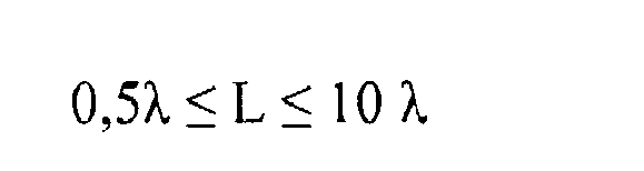
wobei λ die Wellenlänge der Übermittlung durch das Deckgestein ist, und L die Entfernung zwischen dem Transmitter und dem Empfänger ist. - Verfahren nach einem der Ansprüche 19 bis 23, dadurch gekennzeichnet, dass die Transmissionsfrequenz im Bereich von 0,01 Hz bis 1 kHz ist.
- Verfahren nach Anspruch 24, dadurch gekennzeichnet, dass die Transmissionsfrequenz im Bereich von 0,1 bis 20 Hz ist.
- Verfahren nach einem der vorhergehenden Ansprüche, dadurch gekennzeichnet, dass der seismische Empfänger eine komplette seismische Aufzeichnung der Ablaufkomponenten aufzeichnet, welche drei Verlagerungsvektor-Komponenten und eine Druckkomponente aufweist.
- Vorrichtung zur Verwendung bei der Durchführung des Verfahrens nach einem der vorhergehenden Ansprüche, welche eine Empfängereinheit enthält, mit: einer Tragestruktur; einer auf die Tragestruktur montierten elektrischen Dipol-Empfangsantenne; einem auf die Tragestruktur montierten dreiachsigen seismischen Empfänger; einer auf die Tragestruktur montierten Geophoneinheit; einem auf die Tragestruktur montierten Hydrophon; und einem Anker, der ausgebildet ist, um die Tragestruktur am Meeresboden zu befestigen.
Applications Claiming Priority (2)
| Application Number | Priority Date | Filing Date | Title |
|---|---|---|---|
| GB0306059A GB2399640B (en) | 2003-03-17 | 2003-03-17 | Method and apparatus for determining the nature of submarine reservoirs |
| PCT/GB2004/001144 WO2004083898A1 (en) | 2003-03-17 | 2004-03-17 | Method and apparatus for determining the nature of submarine reservoirs |
Publications (2)
| Publication Number | Publication Date |
|---|---|
| EP1613982A1 EP1613982A1 (de) | 2006-01-11 |
| EP1613982B1 true EP1613982B1 (de) | 2007-01-17 |
Family
ID=9954916
Family Applications (1)
| Application Number | Title | Priority Date | Filing Date |
|---|---|---|---|
| EP04721228A Revoked EP1613982B1 (de) | 2003-03-17 | 2004-03-17 | Verfahren und vorrichtung zur bestimmung der beschaffenheit von unterwasserreservoirs |
Country Status (23)
| Country | Link |
|---|---|
| US (1) | US7567084B2 (de) |
| EP (1) | EP1613982B1 (de) |
| CN (1) | CN100335917C (de) |
| AP (1) | AP1946A (de) |
| AT (1) | ATE352047T1 (de) |
| AU (1) | AU2004221305B2 (de) |
| BR (1) | BRPI0408383A (de) |
| CA (1) | CA2518939A1 (de) |
| CO (1) | CO5660316A2 (de) |
| CY (1) | CY1105946T1 (de) |
| DE (1) | DE602004004386T2 (de) |
| DK (1) | DK1613982T3 (de) |
| EG (1) | EG23543A (de) |
| ES (1) | ES2277246T3 (de) |
| GB (1) | GB2399640B (de) |
| MA (1) | MA27755A1 (de) |
| MX (1) | MXPA05009984A (de) |
| MY (1) | MY137895A (de) |
| NO (1) | NO20054736L (de) |
| OA (1) | OA13110A (de) |
| RU (1) | RU2361248C2 (de) |
| WO (1) | WO2004083898A1 (de) |
| ZA (1) | ZA200507358B (de) |
Families Citing this family (48)
| Publication number | Priority date | Publication date | Assignee | Title |
|---|---|---|---|---|
| NO326506B1 (no) * | 2003-07-10 | 2008-12-15 | Norsk Hydro As | Et maringeofysisk innsamlingssystem med en kabel med seismiske kilder og mottakere og elektromagnteiske kilder og mottakere |
| US8995224B2 (en) | 2003-08-22 | 2015-03-31 | Schlumberger Technology Corporation | Real-time velocity and pore-pressure prediction ahead of drill bit |
| US7782709B2 (en) | 2003-08-22 | 2010-08-24 | Schlumberger Technology Corporation | Multi-physics inversion processing to predict pore pressure ahead of the drill bit |
| GB2409900B (en) | 2004-01-09 | 2006-05-24 | Statoil Asa | Processing seismic data representing a physical system |
| GB2420855B (en) | 2004-12-02 | 2009-08-26 | Electromagnetic Geoservices As | Source for electromagnetic surveying |
| NO323490B1 (no) * | 2005-01-10 | 2007-05-29 | Norsk Hydro As | Elektromagnetisk hydrokarbonprospektering i grunne havomrader |
| US7383132B2 (en) | 2005-03-07 | 2008-06-03 | Exxonmobil Upstream Research Co. | Method for identifying resistivity anomalies in electromagnetic survey data |
| US7643942B2 (en) | 2005-06-10 | 2010-01-05 | Exxonmobil Upstream Research Company | Method for controlled source electromagnetic reconnaissance surveying |
| US7330790B2 (en) * | 2005-10-03 | 2008-02-12 | Seismic Sciences, Inc. | Method of seismo electromagnetic detecting of hydrocarbon deposits |
| GB2434868B (en) | 2006-02-06 | 2010-05-12 | Statoil Asa | Method of conducting a seismic survey |
| GB2435693A (en) | 2006-02-09 | 2007-09-05 | Electromagnetic Geoservices As | Seabed electromagnetic surveying |
| GB2439378B (en) | 2006-06-09 | 2011-03-16 | Electromagnetic Geoservices As | Instrument for measuring electromagnetic signals |
| GB2441786A (en) * | 2006-09-15 | 2008-03-19 | Electromagnetic Geoservices As | Combined electromagnetic and seismic surveying |
| GB2442749B (en) | 2006-10-12 | 2010-05-19 | Electromagnetic Geoservices As | Positioning system |
| US7813219B2 (en) * | 2006-11-29 | 2010-10-12 | Baker Hughes Incorporated | Electro-magnetic acoustic measurements combined with acoustic wave analysis |
| GB2445582A (en) | 2007-01-09 | 2008-07-16 | Statoil Asa | Method for analysing data from an electromagnetic survey |
| NO330103B1 (no) | 2007-02-09 | 2011-02-21 | Statoil Asa | Sammenstilling for boring og logging, fremgangsmate for elektropulsboring og logging |
| US7872477B2 (en) * | 2007-04-30 | 2011-01-18 | Kjt Enterprises, Inc. | Multi-component marine electromagnetic signal acquisition cable and system |
| US8026723B2 (en) * | 2007-04-30 | 2011-09-27 | Kjt Enterprises, Inc. | Multi-component marine electromagnetic signal acquisition method |
| US7746077B2 (en) | 2007-04-30 | 2010-06-29 | Kjt Enterprises, Inc. | Method for measuring the magnetotelluric response to the earth's subsurface |
| US7863901B2 (en) * | 2007-05-25 | 2011-01-04 | Schlumberger Technology Corporation | Applications of wideband EM measurements for determining reservoir formation properties |
| US7705599B2 (en) * | 2007-07-09 | 2010-04-27 | Kjt Enterprises, Inc. | Buoy-based marine electromagnetic signal acquisition system |
| US8612194B2 (en) | 2007-08-08 | 2013-12-17 | Westerngeco L.L.C. | Updating a subterranean model using at least electromagnetic data |
| US20090265111A1 (en) * | 2008-04-16 | 2009-10-22 | Kjt Enterprises, Inc. | Signal processing method for marine electromagnetic signals |
| US8055730B2 (en) * | 2008-07-16 | 2011-11-08 | Westerngeco L. L. C. | System having a network connected to multiple different types of survey sensors |
| BRPI0918084A2 (pt) | 2008-09-24 | 2015-12-01 | Exxonmobil Upstream Res Co | método, e, sistema |
| GB2466764B (en) | 2008-10-02 | 2013-03-27 | Electromagnetic Geoservices As | Method for enhanced subsurface electromagnetic sensitivity |
| US8364442B2 (en) | 2009-02-17 | 2013-01-29 | Schlumberger Technology Corporation | Automated structural interpretation |
| US8340912B2 (en) * | 2009-02-17 | 2012-12-25 | Schlumberger Technology Corporation | Seismic attributes for structural analysis |
| US8729903B2 (en) | 2009-11-09 | 2014-05-20 | Exxonmobil Upstream Research Company | Method for remote identification and characterization of hydrocarbon source rocks using seismic and electromagnetic geophysical data |
| GB2481845B (en) | 2010-07-08 | 2014-04-30 | Electromagnetic Geoservices As | Low noise marine electric field sensor system |
| CA2828564C (en) * | 2011-03-02 | 2018-08-28 | Multi-Phase Technologies, Llc | Method and apparatus for measuring the electrical impedance properties of geological formations using multiple simultaneous current sources |
| US20120323541A1 (en) * | 2011-06-14 | 2012-12-20 | Seoul National University R&Db Foundation | Seismic imaging method considering a contour of the sea bottom |
| WO2012174516A1 (en) * | 2011-06-16 | 2012-12-20 | Schlumberger Canada Limited | Method of mapping a subterranean formation based upon wellbore position and seismic data and related system |
| RU2486550C1 (ru) * | 2012-01-10 | 2013-06-27 | Учреждение Российской академии наук Институт проблем нефти и газа РАН | Способ поиска залежей углеводородов в осадочной толще |
| US10310123B2 (en) * | 2012-03-09 | 2019-06-04 | Cgg Services Sas | Seismic reflection full waveform inversion for reflected seismic data |
| US9753167B2 (en) * | 2012-07-23 | 2017-09-05 | Westerngeco L.L.C. | Calibrating rotation data and translational data |
| RU2559046C2 (ru) * | 2013-02-14 | 2015-08-10 | Общество с ограниченной ответственностью научно-производственная фирма "Мезон" | Способ поиска углеводородов |
| RU2527322C1 (ru) * | 2013-04-12 | 2014-08-27 | Федеральное Государственное Унитарное Предприятие "Сибирский Научно-Исследовательский Институт Геологии, Геофизики И Минерального Сырья" | Способ геофизической разведки залежей углеводородов |
| US11092710B2 (en) | 2013-06-27 | 2021-08-17 | Pgs Geophysical As | Inversion techniques using streamers at different depths |
| US10459100B2 (en) | 2013-06-27 | 2019-10-29 | Pgs Geophysical As | Survey techniques using streamers at different depths |
| US9651707B2 (en) | 2013-06-28 | 2017-05-16 | Cgg Services Sas | Methods and systems for joint seismic and electromagnetic data recording |
| RU2615515C2 (ru) * | 2013-10-29 | 2017-04-05 | Учреждение Российской академии наук Институт космофизических исследований и распространения радиоволн Дальневосточного отделения РАН | Способ дистанционного измерения напряжений в недрах сквозь толщу поглощающей породы в условиях сильных помех |
| CN104879126B (zh) * | 2015-05-14 | 2017-09-26 | 中国石油天然气集团公司 | 一种基于阵列感应测井的碎屑岩储层流体识别方法 |
| US10379256B2 (en) | 2015-12-16 | 2019-08-13 | Pgs Geophysical As | Combined seismic and electromagnetic survey configurations |
| RU2657128C2 (ru) * | 2016-06-30 | 2018-06-08 | Федеральное государственное бюджетное учреждение "Всероссийский научно-исследовательский институт геологии и минеральных ресурсов Мирового океана имени академика И.С. Грамберга" | Способ комплексной системы поиска и разведки месторождений углеводородов сейсмическими и электромагнитными методами в шельфовой зоне |
| RU2680262C1 (ru) * | 2017-12-07 | 2019-02-19 | Федеральное государственное бюджетное учреждение науки Институт земного магнетизма, ионосферы и распространения радиоволн им. Н.В. Пушкова Российской академии наук (ИЗМИРАН) | Способ определения глубины залегания изотермы Кюри |
| GB2642188A (en) * | 2024-06-25 | 2026-01-07 | Univ Oxford Innovation Ltd | Sub-surface detection |
Family Cites Families (134)
| Publication number | Priority date | Publication date | Assignee | Title |
|---|---|---|---|---|
| US2077707A (en) | 1933-08-01 | 1937-04-20 | Melton Benjamin Starr | Electromagnetic prospecting method |
| US2531088A (en) | 1947-10-16 | 1950-11-21 | Standard Oil Dev Co | Electrical prospecting method |
| US2907389A (en) | 1956-06-18 | 1959-10-06 | Phillips Petroleum Co | Recovery of oil from oil sands and the like |
| US3052836A (en) | 1957-12-24 | 1962-09-04 | Shell Oil Co | Method for marine electrical prospecting |
| FR1313189A (fr) * | 1961-11-07 | 1962-12-28 | Cie Generale De Geophysique Et | Perfectionnements aux procédés de prospection sismique |
| US3332487A (en) | 1963-09-30 | 1967-07-25 | Pan American Petroleum Corp | Aerobic bacteria in oil recovery |
| US3398356A (en) | 1964-02-10 | 1968-08-20 | Westinghouse Electric Corp | Method utilizing a pair of subsurface antennas for determining the physical properties effecting radio energy propagation through earth |
| GB1239953A (en) | 1967-06-06 | 1971-07-21 | Rech S Geol Et Minieres Bureau | Improvements in or relating to methods and apparatus for determining the electrical resistance of the sub-soil |
| US3836960A (en) | 1970-03-12 | 1974-09-17 | Gen Dynamics Corp | Sensor system |
| US4010413A (en) | 1971-08-23 | 1977-03-01 | Geo-Nav, Inc. | Plural frequency geological exploration system and method with phase comparison |
| US3806795A (en) | 1972-01-03 | 1974-04-23 | Geophysical Survey Sys Inc | Geophysical surveying system employing electromagnetic impulses |
| US3975674A (en) * | 1972-09-29 | 1976-08-17 | Mceuen Robert B | Geothermal exploration method utilizing electrical resistivity and seismic velocity |
| US4168484A (en) | 1972-10-16 | 1979-09-18 | Bolt Beranek And Newman Inc. | Method of and apparatus for radiant energy measurement of impedance transitions in media, for identification and related purposes |
| GB1456009A (en) | 1973-06-25 | 1976-11-17 | Central Geophysics Ltd | Method for exciting and detecing resonant oscillations from electronic conductors in the earth |
| FR2288988A1 (fr) | 1974-07-30 | 1976-05-21 | Duroux Jean | Procede et appareil de prospection en mer par mesure de champs electromagnetiques |
| US4079309A (en) | 1976-09-03 | 1978-03-14 | The United States Of America As Represented By The Secretary Of The Navy | Method for determining changes in earth resistivity by measuring phase difference between magnetic field components |
| FR2390743A1 (fr) | 1977-05-09 | 1978-12-08 | Geophysique Cie Gle | Prospection electromagnetique du sous-sol par induction, associee a une prospection par sondage electrique |
| US4296379A (en) | 1977-08-25 | 1981-10-20 | Eizaburo Yoshizumi | Ground prospecting method utilizing electrical resistivity measurements for measuring the resistivity of unit blocks of the ground |
| US4258321A (en) | 1978-03-09 | 1981-03-24 | Neale Jr Dory J | Radio geophysical surveying method and apparatus |
| US4308499A (en) | 1978-05-26 | 1981-12-29 | Kali Und Salz A.G. | Method utilizing electromagnetic wave pulses for determining the locations of boundary surfaces of underground mineral deposits |
| US4446434A (en) | 1978-12-20 | 1984-05-01 | Conoco Inc. | Hydrocarbon prospecting method with changing of electrode spacing for the indirect detection of hydrocarbon reservoirs |
| US5025218A (en) | 1979-04-23 | 1991-06-18 | The United States Of America As Represented By The Secretary Of The Navy | Pulsed field system for detecting the presence of a target in a subsurface environment |
| MA18895A1 (fr) | 1979-07-09 | 1981-04-01 | Cie Generale De Geophysique Sa | Procede et dispositif de prospection geophysique a courants transitoires |
| SE419269B (sv) | 1979-11-29 | 1981-07-20 | Boliden Ab | Forfarande och anordning for bestemning av markens elektriska ledningsformaga |
| FR2479992A1 (fr) | 1980-04-03 | 1981-10-09 | Duroux Jean | Procede de prospection geophysique par reflexion electromagnetique par mesure du champ electrique reflechi et moyen de mise en oeuvre par emetteur et recepteur rapproches |
| FR2497360A1 (fr) | 1980-12-31 | 1982-07-02 | Schlumberger Prospection | Mesure de phase et d'amplitude pour un systeme de diagraphie des proprietes dielectriques |
| US4456067A (en) | 1981-04-03 | 1984-06-26 | Marathon Oil Company | Process for inhibiting hydrate formation in producing gas wells |
| US4451789A (en) | 1981-09-28 | 1984-05-29 | Nl Industries, Inc. | Logging tool and method for measuring resistivity of different radial zones at a common depth of measurement |
| US4506225A (en) | 1981-12-28 | 1985-03-19 | Barringer Research Limited | Method for remote measurement of anomalous complex variations of a predetermined electrical parameter in a target zone |
| US4489276A (en) | 1982-01-20 | 1984-12-18 | The United States Of America As Represented By The United States Department Of Energy | Dual-cone double-helical downhole logging device |
| CA1133058A (en) | 1982-02-18 | 1982-10-05 | Geonics Limited | Electromagnetic geophysical surveying system |
| SU1053044A1 (ru) * | 1982-07-28 | 1983-11-07 | Baluev Sergej K | Способ волнового электромагнитного каротажа |
| PL141895B1 (en) | 1983-03-03 | 1987-09-30 | Instytut Gornictwa Naftowego Gaz | Method of and system for direct prospecting of hydrocarbon accumulations |
| US4594551A (en) | 1983-03-31 | 1986-06-10 | Texaco Inc. | Method of deep penetration well logging using three receivers |
| US4583095A (en) | 1983-08-22 | 1986-04-15 | Glen Peterson | Radar seismograph improvement |
| US4617518A (en) | 1983-11-21 | 1986-10-14 | Exxon Production Research Co. | Method and apparatus for offshore electromagnetic sounding utilizing wavelength effects to determine optimum source and detector positions |
| GB8331546D0 (en) | 1983-11-25 | 1984-01-04 | Exxon Research Engineering Co | Polymeric compositions |
| US4616184A (en) | 1984-06-27 | 1986-10-07 | The United States Of America As Represented By The United States Department Of Energy | CSAMT method for determining depth and shape of a sub-surface conductive object |
| JPS61107181A (ja) | 1984-10-31 | 1986-05-26 | Hitachi Ltd | 物体探査装置及び探査方法 |
| US4652829A (en) | 1984-12-28 | 1987-03-24 | Schlumberger Technology Corp. | Electromagnetic logging apparatus with button antennas for measuring the dielectric constant of formation surrounding a borehole |
| US4670166A (en) | 1985-02-27 | 1987-06-02 | Exxon Chemical Patents Inc. | Polymer article and its use for controlled introduction of reagent into a fluid |
| AU608503B2 (en) | 1985-07-15 | 1991-04-11 | Chevron Research And Technology Company | Method of avoiding stuck drilling equipment |
| DE3529466A1 (de) | 1985-08-16 | 1987-04-09 | Pipeline Engineering Ges Fuer | Verfahren zur bestimmung der grenzen von unterirdischen erdgas-lagerstaetten |
| US4686477A (en) | 1985-09-30 | 1987-08-11 | Mobil Oil Corporation | Multiple frequency electric excitation method and identifying complex lithologies of subsurface formations |
| US5570024A (en) | 1986-11-04 | 1996-10-29 | Paramagnetic Logging, Inc. | Determining resistivity of a formation adjacent to a borehole having casing using multiple electrodes and with resistances being defined between the electrodes |
| US5633590A (en) | 1986-11-04 | 1997-05-27 | Paramagnetic Logging, Inc. | Formation resistivity measurements from within a cased well used to quantitatively determine the amount of oil and gas present |
| US4835474A (en) | 1986-11-24 | 1989-05-30 | Southwest Research Institute | Method and apparatus for detecting subsurface anomalies |
| US4906575A (en) | 1987-03-06 | 1990-03-06 | Chevron Research Company | Phosphate compound that is used in a microbial profile modification process |
| US4971151A (en) | 1988-04-19 | 1990-11-20 | B.W.N. Live-Oil Pty. Ltd. | Recovery of oil from oil reservoirs |
| SU1594469A1 (ru) * | 1988-05-10 | 1990-09-23 | Южное Отделение Всесоюзного Научно-Исследовательского Института Геофизических Методов Разведки | Способ многоволновой сейсмической разведки |
| JPH03505781A (ja) | 1988-07-08 | 1991-12-12 | ゼテチック・インターナショナル・リミテッド | 金属及び他の物質の検出 |
| US4986354A (en) | 1988-09-14 | 1991-01-22 | Conoco Inc. | Composition and placement process for oil field chemicals |
| GB8825435D0 (en) | 1988-10-31 | 1988-12-29 | Cross T E | Detection of non metallic material |
| US5103920A (en) | 1989-03-01 | 1992-04-14 | Patton Consulting Inc. | Surveying system and method for locating target subterranean bodies |
| US4957172A (en) | 1989-03-01 | 1990-09-18 | Patton Consulting, Inc. | Surveying method for locating target subterranean bodies |
| US5043667A (en) | 1989-04-21 | 1991-08-27 | Amoco Corporation | Method of magnetotelluric exploration using areal arrays |
| US4992995A (en) | 1989-10-24 | 1991-02-12 | Amoco Corporation | Methods for attenuating noise in seismic data |
| US5066916A (en) | 1990-01-10 | 1991-11-19 | Halliburton Logging Services, Inc. | Technique for separating electromagnetic refracted signals from reflected signals in down hole electromagnetic tools |
| US5185578A (en) | 1990-01-17 | 1993-02-09 | Stolar, Inc. | Method for detecting anomalous geological zones by transmitting electromagnetic energy between spaced drillholes using different frequency ranges |
| US5044435A (en) | 1990-07-16 | 1991-09-03 | Injectech, Inc. | Enhanced oil recovery using denitrifying microorganisms |
| US5083611A (en) | 1991-01-18 | 1992-01-28 | Phillips Petroleum Company | Nutrient injection method for subterranean microbial processes |
| GB2252342B (en) | 1991-01-29 | 1995-01-11 | Norske Stats Oljeselskap | Method of microbial enhanced oil recovery |
| GB9104491D0 (en) | 1991-03-04 | 1991-04-17 | Archaeus Tech Group | Stimulation of oil production |
| DK42491D0 (da) | 1991-03-11 | 1991-03-11 | Kristen Nielsen | Apparat og fremgangsmaade til detektering af nedgravede roer og kabler |
| US5877995A (en) | 1991-05-06 | 1999-03-02 | Exxon Production Research Company | Geophysical prospecting |
| US5280284A (en) | 1991-06-11 | 1994-01-18 | Johler J Ralph | Method of determining the electrical properties of the earth by processing electromagnetic signals propagated through the earth from a capacitor |
| US5192952A (en) | 1991-06-11 | 1993-03-09 | Johler J Ralph | Method and apparatus for transmitting electromagnetic signals into the earth from a capacitor |
| US5230386A (en) | 1991-06-14 | 1993-07-27 | Baker Hughes Incorporated | Method for drilling directional wells |
| USH1490H (en) | 1992-09-28 | 1995-09-05 | Exxon Production Research Company | Marine geophysical prospecting system |
| USH1524H (en) | 1993-01-15 | 1996-04-02 | Exxon Production Research Company | Method for using electromagnetic grounded antennas as directional geophones |
| US5486764A (en) | 1993-01-15 | 1996-01-23 | Exxon Production Research Company | Method for determining subsurface electrical resistance using electroseismic measurements |
| US5373443A (en) | 1993-10-06 | 1994-12-13 | The Regents, University Of California | Method for imaging with low frequency electromagnetic fields |
| US6060885A (en) | 1993-10-14 | 2000-05-09 | Western Atlas International, Inc. | Method and apparatus for determining the resistivity and conductivity of geological formations surrounding a borehole |
| US5563513A (en) | 1993-12-09 | 1996-10-08 | Stratasearch Corp. | Electromagnetic imaging device and method for delineating anomalous resistivity patterns associated with oil and gas traps |
| US5400030A (en) | 1994-02-09 | 1995-03-21 | Exxon Production Research Company | Detection and mapping of hydrocarbon reservoirs with radar waves |
| RU2066466C1 (ru) * | 1994-02-14 | 1996-09-10 | Дальневосточный государственный технический университет | Способ измерения параметров физических полей |
| US5892361A (en) | 1994-03-14 | 1999-04-06 | Baker Hughes Incorporated | Use of raw amplitude and phase in propagation resistivity measurements to measure borehole environmental parameters |
| US5811973A (en) | 1994-03-14 | 1998-09-22 | Baker Hughes Incorporated | Determination of dielectric properties with propagation resistivity tools using both real and imaginary components of measurements |
| US6060884A (en) | 1994-03-14 | 2000-05-09 | Meyer, Jr.; Wallace Harold | Method and apparatus for measuring electromagnetic properties of materials in borehole environs and simultaneously determining the quality of the measurements |
| NO314646B1 (no) | 1994-08-15 | 2003-04-22 | Western Atlas Int Inc | Transient-elektromagnetisk måleverktöy og fremgangsmåte for bruk i en brönn |
| JP3423948B2 (ja) | 1994-08-25 | 2003-07-07 | ジオ・サーチ株式会社 | 地中探査方法及び地中探査装置 |
| USH1561H (en) | 1994-09-22 | 1996-07-02 | Exxon Production Research Company | Method and apparatus for detection of seismic and electromagnetic waves |
| US5581024A (en) | 1994-10-20 | 1996-12-03 | Baker Hughes Incorporated | Downhole depth correlation and computation apparatus and methods for combining multiple borehole measurements |
| AU1336695A (en) * | 1994-12-06 | 1996-06-26 | David F. Farnsworth | Method for forecasting an earthquake from precusor signals |
| GB2296567A (en) | 1994-12-24 | 1996-07-03 | Geco As | Source signature determination and multiple reflection reduction |
| JPH08186098A (ja) | 1994-12-27 | 1996-07-16 | Ryoden Semiconductor Syst Eng Kk | 感光性樹脂の除去方法および除去装置 |
| FR2729222A1 (fr) | 1995-01-10 | 1996-07-12 | Commissariat Energie Atomique | Determination de la porosite et de la permeabilite d'une formation geologique a partir du phenomene d'electrofiltration |
| RU2100829C1 (ru) | 1995-03-06 | 1997-12-27 | Акционерное общество "Новокуйбышевский нефтеперерабатывающий завод" | Способ поиска нефтепродуктов в земле |
| WO1996033426A1 (en) | 1995-04-21 | 1996-10-24 | Soerensen Kurt I | A method and measurement equipment for mapping the geology in a subterranean formation |
| DE19518420C2 (de) | 1995-05-19 | 1998-01-02 | Diether Alfred Schroeder | Schaltungsanordnung zur Verwendung in einem geophysikalischen Prospektionsverfahren |
| GB2301902A (en) | 1995-06-08 | 1996-12-18 | Baker Hughes Inc | Detecting boundaries between strata while drilling a borehole |
| US5553407A (en) | 1995-06-19 | 1996-09-10 | Vermeer Manufacturing Company | Excavator data acquisition and control system and method of use |
| GB2304483B (en) | 1995-08-18 | 2000-03-29 | London Electricity Plc | System for and method of determining the location of an object in a medium |
| US6023168A (en) | 1995-08-21 | 2000-02-08 | Schlumberger Technology Corporation | Apparatus and method for measuring the resistivity of underground formations |
| GB2304895B (en) | 1995-08-25 | 1999-05-19 | Geco Prakla | Method of and apparatus for controlling the quality of processed seismic data |
| FR2738920B1 (fr) | 1995-09-19 | 1997-11-14 | Elf Aquitaine | Methode de reconnaissance automatique de facies sismiques |
| FR2738871B1 (fr) | 1995-09-19 | 1997-11-14 | Elf Aquitaine | Procede pour realiser une representation des textures d'une structure geologique |
| GB9521171D0 (en) | 1995-10-17 | 1995-12-20 | Millar John W A | Detection method |
| US5831935A (en) | 1996-03-05 | 1998-11-03 | Chevron U.S.A. Inc. | Method for geophysical processing and interpretation using seismic trace difference for analysis and display |
| US5886526A (en) | 1996-06-19 | 1999-03-23 | Schlumberger Technology Corporation | Apparatus and method for determining properties of anisotropic earth formations |
| US5901795A (en) | 1996-06-25 | 1999-05-11 | Exxon Production Research Company | Well collision avoidance |
| US5777478A (en) | 1996-08-27 | 1998-07-07 | John R. Jackson | Passive geophysical prospecting apparatus and method based upon detection of discontinuities associated with extremely low frequency electromagnetic fields |
| US5825188A (en) | 1996-11-27 | 1998-10-20 | Montgomery; Jerry R. | Method of mapping and monitoring groundwater and subsurface aqueous systems |
| US5841280A (en) | 1997-06-24 | 1998-11-24 | Western Atlas International, Inc. | Apparatus and method for combined acoustic and seismoelectric logging measurements |
| AU9087398A (en) | 1997-09-15 | 1999-04-05 | Den Norske Stats Oljeselskap A.S. | Fluid separation system |
| US6188222B1 (en) | 1997-09-19 | 2001-02-13 | Schlumberger Technology Corporation | Method and apparatus for measuring resistivity of an earth formation |
| US6026913A (en) | 1997-09-30 | 2000-02-22 | Halliburton Energy Services, Inc. | Acoustic method of connecting boreholes for multi-lateral completion |
| US5987388A (en) | 1997-12-26 | 1999-11-16 | Atlantic Richfield Company | Automated extraction of fault surfaces from 3-D seismic prospecting data |
| GB9800741D0 (en) | 1998-01-15 | 1998-03-11 | Geco As | Multiple attenuation of multi-component sea-bottom data |
| US6114972A (en) | 1998-01-20 | 2000-09-05 | Halliburton Energy Services, Inc. | Electromagnetic resistivity tool and method for use of same |
| NO315725B1 (no) | 1998-06-18 | 2003-10-13 | Norges Geotekniske Inst | Anordning for måling og overvåking av resistivitet utenfor et brönnrör i etpetroleumsreservoar |
| US6236212B1 (en) | 1998-06-22 | 2001-05-22 | The United States Of America As Represented By The Secretary Of The Interior | Induced polarization system using towed cable carrying transmitters and receivers for identifying minerals on the ocean floor |
| WO2000004701A1 (en) * | 1998-07-16 | 2000-01-27 | Intervoice Limited Partnership | System and method for managing prepaid wireless service |
| US6188221B1 (en) | 1998-08-07 | 2001-02-13 | Van De Kop Franz | Method and apparatus for transmitting electromagnetic waves and analyzing returns to locate underground fluid deposits |
| GB9818875D0 (en) | 1998-08-28 | 1998-10-21 | Norske Stats Oljeselskap | Method and apparatus for determining the nature of subterranean reservoirs |
| US6573855B1 (en) | 1998-08-31 | 2003-06-03 | Osaka Gas Co., Ltd. | Three-dimensional questing method, three-dimensional voxel data displaying method, and device therefor |
| DE60006647T2 (de) | 1999-01-13 | 2004-09-30 | Vermeer Mfg. Co., Pella | Automatisiertes bohrplanungsverfahren und vorrichtung zum horizontalen richtungsbohren |
| US6163155A (en) | 1999-01-28 | 2000-12-19 | Dresser Industries, Inc. | Electromagnetic wave resistivity tool having a tilted antenna for determining the horizontal and vertical resistivities and relative dip angle in anisotropic earth formations |
| US6184685B1 (en) | 1999-02-22 | 2001-02-06 | Halliburton Energy Services, Inc. | Mulitiple spacing resistivity measurements with receiver arrays |
| US6181138B1 (en) | 1999-02-22 | 2001-01-30 | Halliburton Energy Services, Inc. | Directional resistivity measurements for azimuthal proximity detection of bed boundaries |
| US6339333B1 (en) | 1999-03-12 | 2002-01-15 | Profile Technologies, Inc. | Dynamic electromagnetic methods for direct prospecting for oil |
| GB9909040D0 (en) | 1999-04-20 | 1999-06-16 | Flight Refueling Ltd | Systems and methods for locating subsurface objects |
| GB2349222B (en) * | 1999-04-21 | 2001-10-31 | Geco Prakla | Method and system for electroseismic monitoring of microseismicity |
| US6294917B1 (en) | 1999-09-13 | 2001-09-25 | Electromagnetic Instruments, Inc. | Electromagnetic induction method and apparatus for the measurement of the electrical resistivity of geologic formations surrounding boreholes cased with a conductive liner |
| US6353321B1 (en) | 2000-01-27 | 2002-03-05 | Halliburton Energy Services, Inc. | Uncompensated electromagnetic wave resistivity tool for bed boundary detection and invasion profiling |
| GB0002422D0 (en) * | 2000-02-02 | 2000-03-22 | Norske Stats Oljeselskap | Method and apparatus for determining the nature of subterranean reservoirs |
| CN1246706C (zh) | 2000-08-14 | 2006-03-22 | 电磁地形服务公司 | 确定地下储层性质的方法和设备 |
| DE10117730A1 (de) | 2001-04-09 | 2002-10-10 | Basf Ag | Umsetzung von (Di)Aminen in Gegenwart einer Lysinoxidase und eines Reduktionsmittels |
| GB2378511B (en) | 2001-08-07 | 2005-12-28 | Statoil Asa | Method and apparatus for determining the nature of subterranean reservoirs |
| GB2383133A (en) | 2001-08-07 | 2003-06-18 | Statoil Asa | Investigation of subterranean reservoirs |
| US6541975B2 (en) * | 2001-08-23 | 2003-04-01 | Kjt Enterprises, Inc. | Integrated borehole system for reservoir detection and monitoring |
| GB2381137B (en) | 2001-10-15 | 2004-03-03 | Univ Southampton | Signal generation apparatus and method for seafloor electromagnetic exploration |
| GB2382875B (en) | 2001-12-07 | 2004-03-03 | Univ Southampton | Electromagnetic surveying for hydrocarbon reservoirs |
| US6842006B2 (en) | 2002-06-27 | 2005-01-11 | Schlumberger Technology Corporation | Marine electromagnetic measurement system |
-
2003
- 2003-03-17 GB GB0306059A patent/GB2399640B/en not_active Expired - Lifetime
-
2004
- 2004-03-17 DK DK04721228T patent/DK1613982T3/da active
- 2004-03-17 AT AT04721228T patent/ATE352047T1/de not_active IP Right Cessation
- 2004-03-17 RU RU2005131965/28A patent/RU2361248C2/ru not_active IP Right Cessation
- 2004-03-17 DE DE602004004386T patent/DE602004004386T2/de not_active Revoked
- 2004-03-17 MY MYPI20040932A patent/MY137895A/en unknown
- 2004-03-17 ES ES04721228T patent/ES2277246T3/es not_active Expired - Lifetime
- 2004-03-17 CA CA002518939A patent/CA2518939A1/en not_active Abandoned
- 2004-03-17 MX MXPA05009984A patent/MXPA05009984A/es active IP Right Grant
- 2004-03-17 WO PCT/GB2004/001144 patent/WO2004083898A1/en not_active Ceased
- 2004-03-17 CN CNB2004800071270A patent/CN100335917C/zh not_active Expired - Fee Related
- 2004-03-17 BR BRPI0408383-0A patent/BRPI0408383A/pt not_active IP Right Cessation
- 2004-03-17 OA OA1200500263A patent/OA13110A/en unknown
- 2004-03-17 AU AU2004221305A patent/AU2004221305B2/en not_active Ceased
- 2004-03-17 AP AP2005003398A patent/AP1946A/xx active
- 2004-03-17 EG EG2004030124A patent/EG23543A/xx active
- 2004-03-17 EP EP04721228A patent/EP1613982B1/de not_active Revoked
- 2004-03-17 US US10/549,660 patent/US7567084B2/en not_active Expired - Fee Related
-
2005
- 2005-09-13 ZA ZA200507358A patent/ZA200507358B/en unknown
- 2005-10-03 MA MA28532A patent/MA27755A1/fr unknown
- 2005-10-12 CO CO05104371A patent/CO5660316A2/es not_active Application Discontinuation
- 2005-10-14 NO NO20054736A patent/NO20054736L/no unknown
-
2007
- 2007-01-25 CY CY20071100086T patent/CY1105946T1/el unknown
Also Published As
| Publication number | Publication date |
|---|---|
| NO20054736D0 (no) | 2005-10-14 |
| WO2004083898A1 (en) | 2004-09-30 |
| US7567084B2 (en) | 2009-07-28 |
| US20060197532A1 (en) | 2006-09-07 |
| CN100335917C (zh) | 2007-09-05 |
| DE602004004386D1 (de) | 2007-03-08 |
| DK1613982T3 (da) | 2007-03-19 |
| EG23543A (en) | 2006-05-07 |
| RU2361248C2 (ru) | 2009-07-10 |
| RU2005131965A (ru) | 2006-05-27 |
| ZA200507358B (en) | 2006-11-29 |
| CN1761889A (zh) | 2006-04-19 |
| GB2399640A (en) | 2004-09-22 |
| ATE352047T1 (de) | 2007-02-15 |
| MA27755A1 (fr) | 2006-02-01 |
| CO5660316A2 (es) | 2006-07-31 |
| AP1946A (en) | 2009-02-04 |
| MXPA05009984A (es) | 2006-03-09 |
| EP1613982A1 (de) | 2006-01-11 |
| DE602004004386T2 (de) | 2007-10-18 |
| AU2004221305B2 (en) | 2009-12-10 |
| CA2518939A1 (en) | 2004-09-30 |
| NO20054736L (no) | 2005-12-15 |
| AU2004221305A1 (en) | 2004-09-30 |
| MY137895A (en) | 2009-03-31 |
| GB2399640B (en) | 2007-02-21 |
| BRPI0408383A (pt) | 2006-03-21 |
| AP2005003398A0 (en) | 2005-12-31 |
| ES2277246T3 (es) | 2007-07-01 |
| CY1105946T1 (el) | 2011-04-06 |
| OA13110A (en) | 2006-11-10 |
| GB0306059D0 (en) | 2003-04-23 |
Similar Documents
| Publication | Publication Date | Title |
|---|---|---|
| EP1613982B1 (de) | Verfahren und vorrichtung zur bestimmung der beschaffenheit von unterwasserreservoirs | |
| US6717411B2 (en) | Electromagnetic method and apparatus for determining the nature of subterranean reservoirs using refracted electromagnetic waves | |
| US6696839B2 (en) | Electromagnetic methods and apparatus for determining the content of subterranean reservoirs | |
| EP1256019B2 (de) | Methode zur bestimmung der natur eines unterirdischen reservoirs | |
| US20100045295A1 (en) | Method and apparatus for determining the nature of submarine reservoirs | |
| US8188748B2 (en) | Electromagnetic surveying |
Legal Events
| Date | Code | Title | Description |
|---|---|---|---|
| PUAI | Public reference made under article 153(3) epc to a published international application that has entered the european phase |
Free format text: ORIGINAL CODE: 0009012 |
|
| 17P | Request for examination filed |
Effective date: 20051017 |
|
| AK | Designated contracting states |
Kind code of ref document: A1 Designated state(s): AT BE BG CH CY CZ DE DK EE ES FI FR GB GR HU IE IT LI LU MC NL PL PT RO SE SI SK TR |
|
| AX | Request for extension of the european patent |
Extension state: AL LT LV MK |
|
| DAX | Request for extension of the european patent (deleted) | ||
| GRAP | Despatch of communication of intention to grant a patent |
Free format text: ORIGINAL CODE: EPIDOSNIGR1 |
|
| GRAS | Grant fee paid |
Free format text: ORIGINAL CODE: EPIDOSNIGR3 |
|
| GRAA | (expected) grant |
Free format text: ORIGINAL CODE: 0009210 |
|
| AK | Designated contracting states |
Kind code of ref document: B1 Designated state(s): AT BE BG CH CY CZ DE DK EE ES FI FR GB GR HU IE IT LI LU MC NL PL PT RO SE SI SK TR |
|
| PG25 | Lapsed in a contracting state [announced via postgrant information from national office to epo] |
Ref country code: CH Free format text: LAPSE BECAUSE OF FAILURE TO SUBMIT A TRANSLATION OF THE DESCRIPTION OR TO PAY THE FEE WITHIN THE PRESCRIBED TIME-LIMIT Effective date: 20070117 Ref country code: LI Free format text: LAPSE BECAUSE OF FAILURE TO SUBMIT A TRANSLATION OF THE DESCRIPTION OR TO PAY THE FEE WITHIN THE PRESCRIBED TIME-LIMIT Effective date: 20070117 Ref country code: SI Free format text: LAPSE BECAUSE OF FAILURE TO SUBMIT A TRANSLATION OF THE DESCRIPTION OR TO PAY THE FEE WITHIN THE PRESCRIBED TIME-LIMIT Effective date: 20070117 Ref country code: FI Free format text: LAPSE BECAUSE OF FAILURE TO SUBMIT A TRANSLATION OF THE DESCRIPTION OR TO PAY THE FEE WITHIN THE PRESCRIBED TIME-LIMIT Effective date: 20070117 Ref country code: AT Free format text: LAPSE BECAUSE OF FAILURE TO SUBMIT A TRANSLATION OF THE DESCRIPTION OR TO PAY THE FEE WITHIN THE PRESCRIBED TIME-LIMIT Effective date: 20070117 Ref country code: PL Free format text: LAPSE BECAUSE OF FAILURE TO SUBMIT A TRANSLATION OF THE DESCRIPTION OR TO PAY THE FEE WITHIN THE PRESCRIBED TIME-LIMIT Effective date: 20070117 |
|
| REG | Reference to a national code |
Ref country code: GB Ref legal event code: FG4D |
|
| REG | Reference to a national code |
Ref country code: GR Ref legal event code: EP Ref document number: 20070400323 Country of ref document: GR Ref country code: CH Ref legal event code: EP |
|
| REG | Reference to a national code |
Ref country code: IE Ref legal event code: FG4D |
|
| REF | Corresponds to: |
Ref document number: 602004004386 Country of ref document: DE Date of ref document: 20070308 Kind code of ref document: P |
|
| REG | Reference to a national code |
Ref country code: DK Ref legal event code: T3 |
|
| PG25 | Lapsed in a contracting state [announced via postgrant information from national office to epo] |
Ref country code: BG Free format text: LAPSE BECAUSE OF FAILURE TO SUBMIT A TRANSLATION OF THE DESCRIPTION OR TO PAY THE FEE WITHIN THE PRESCRIBED TIME-LIMIT Effective date: 20070417 Ref country code: SE Free format text: LAPSE BECAUSE OF FAILURE TO SUBMIT A TRANSLATION OF THE DESCRIPTION OR TO PAY THE FEE WITHIN THE PRESCRIBED TIME-LIMIT Effective date: 20070417 |
|
| PLBI | Opposition filed |
Free format text: ORIGINAL CODE: 0009260 |
|
| PG25 | Lapsed in a contracting state [announced via postgrant information from national office to epo] |
Ref country code: PT Free format text: LAPSE BECAUSE OF FAILURE TO SUBMIT A TRANSLATION OF THE DESCRIPTION OR TO PAY THE FEE WITHIN THE PRESCRIBED TIME-LIMIT Effective date: 20070618 |
|
| REG | Reference to a national code |
Ref country code: ES Ref legal event code: FG2A Ref document number: 2277246 Country of ref document: ES Kind code of ref document: T3 |
|
| 26 | Opposition filed |
Opponent name: SCHLUMBERGER HOLDINGS LIMITED Effective date: 20070606 |
|
| ET | Fr: translation filed | ||
| REG | Reference to a national code |
Ref country code: CH Ref legal event code: PL |
|
| REG | Reference to a national code |
Ref country code: GB Ref legal event code: 729U |
|
| NLR1 | Nl: opposition has been filed with the epo |
Opponent name: SCHLUMBERGER HOLDINGS LIMITED |
|
| PLBI | Opposition filed |
Free format text: ORIGINAL CODE: 0009260 |
|
| PLAX | Notice of opposition and request to file observation + time limit sent |
Free format text: ORIGINAL CODE: EPIDOSNOBS2 |
|
| 26 | Opposition filed |
Opponent name: SCHLUMBERGER HOLDINGS LIMITED Effective date: 20070606 Opponent name: OHM LIMITED Effective date: 20071016 |
|
| PG25 | Lapsed in a contracting state [announced via postgrant information from national office to epo] |
Ref country code: GB Free format text: LAPSE BECAUSE OF THE APPLICANT RENOUNCES Effective date: 20070822 Ref country code: SK Free format text: LAPSE BECAUSE OF FAILURE TO SUBMIT A TRANSLATION OF THE DESCRIPTION OR TO PAY THE FEE WITHIN THE PRESCRIBED TIME-LIMIT Effective date: 20070117 |
|
| NLR1 | Nl: opposition has been filed with the epo |
Opponent name: OHM LIMITED Opponent name: SCHLUMBERGER HOLDINGS LIMITED |
|
| PG25 | Lapsed in a contracting state [announced via postgrant information from national office to epo] |
Ref country code: BE Free format text: LAPSE BECAUSE OF FAILURE TO SUBMIT A TRANSLATION OF THE DESCRIPTION OR TO PAY THE FEE WITHIN THE PRESCRIBED TIME-LIMIT Effective date: 20070117 Ref country code: RO Free format text: LAPSE BECAUSE OF FAILURE TO SUBMIT A TRANSLATION OF THE DESCRIPTION OR TO PAY THE FEE WITHIN THE PRESCRIBED TIME-LIMIT Effective date: 20070117 Ref country code: CZ Free format text: LAPSE BECAUSE OF FAILURE TO SUBMIT A TRANSLATION OF THE DESCRIPTION OR TO PAY THE FEE WITHIN THE PRESCRIBED TIME-LIMIT Effective date: 20070117 |
|
| PG25 | Lapsed in a contracting state [announced via postgrant information from national office to epo] |
Ref country code: MC Free format text: LAPSE BECAUSE OF NON-PAYMENT OF DUE FEES Effective date: 20070331 |
|
| PLAF | Information modified related to communication of a notice of opposition and request to file observations + time limit |
Free format text: ORIGINAL CODE: EPIDOSCOBS2 |
|
| PLBB | Reply of patent proprietor to notice(s) of opposition received |
Free format text: ORIGINAL CODE: EPIDOSNOBS3 |
|
| PLAB | Opposition data, opponent's data or that of the opponent's representative modified |
Free format text: ORIGINAL CODE: 0009299OPPO |
|
| PG25 | Lapsed in a contracting state [announced via postgrant information from national office to epo] |
Ref country code: EE Free format text: LAPSE BECAUSE OF FAILURE TO SUBMIT A TRANSLATION OF THE DESCRIPTION OR TO PAY THE FEE WITHIN THE PRESCRIBED TIME-LIMIT Effective date: 20070117 |
|
| PG25 | Lapsed in a contracting state [announced via postgrant information from national office to epo] |
Ref country code: LU Free format text: LAPSE BECAUSE OF NON-PAYMENT OF DUE FEES Effective date: 20070317 |
|
| PG25 | Lapsed in a contracting state [announced via postgrant information from national office to epo] |
Ref country code: HU Free format text: LAPSE BECAUSE OF FAILURE TO SUBMIT A TRANSLATION OF THE DESCRIPTION OR TO PAY THE FEE WITHIN THE PRESCRIBED TIME-LIMIT Effective date: 20070718 |
|
| PGFP | Annual fee paid to national office [announced via postgrant information from national office to epo] |
Ref country code: DK Payment date: 20100310 Year of fee payment: 7 Ref country code: ES Payment date: 20100324 Year of fee payment: 7 Ref country code: IE Payment date: 20100325 Year of fee payment: 7 |
|
| PGFP | Annual fee paid to national office [announced via postgrant information from national office to epo] |
Ref country code: FR Payment date: 20100402 Year of fee payment: 7 |
|
| PGFP | Annual fee paid to national office [announced via postgrant information from national office to epo] |
Ref country code: TR Payment date: 20100223 Year of fee payment: 7 |
|
| PGFP | Annual fee paid to national office [announced via postgrant information from national office to epo] |
Ref country code: DE Payment date: 20100419 Year of fee payment: 7 Ref country code: IT Payment date: 20100326 Year of fee payment: 7 Ref country code: NL Payment date: 20100315 Year of fee payment: 7 |
|
| RDAF | Communication despatched that patent is revoked |
Free format text: ORIGINAL CODE: EPIDOSNREV1 |
|
| PGFP | Annual fee paid to national office [announced via postgrant information from national office to epo] |
Ref country code: CY Payment date: 20100301 Year of fee payment: 7 |
|
| PGFP | Annual fee paid to national office [announced via postgrant information from national office to epo] |
Ref country code: GR Payment date: 20100319 Year of fee payment: 7 |
|
| RDAG | Patent revoked |
Free format text: ORIGINAL CODE: 0009271 |
|
| STAA | Information on the status of an ep patent application or granted ep patent |
Free format text: STATUS: PATENT REVOKED |
|
| 27W | Patent revoked |
Effective date: 20101014 |