EP1614181B1 - Ensemble electrode a membrane avec joint integre - Google Patents
Ensemble electrode a membrane avec joint integre Download PDFInfo
- Publication number
- EP1614181B1 EP1614181B1 EP04760761A EP04760761A EP1614181B1 EP 1614181 B1 EP1614181 B1 EP 1614181B1 EP 04760761 A EP04760761 A EP 04760761A EP 04760761 A EP04760761 A EP 04760761A EP 1614181 B1 EP1614181 B1 EP 1614181B1
- Authority
- EP
- European Patent Office
- Prior art keywords
- membrane electrode
- pad
- compressed
- sealing element
- seal
- Prior art date
- Legal status (The legal status is an assumption and is not a legal conclusion. Google has not performed a legal analysis and makes no representation as to the accuracy of the status listed.)
- Expired - Lifetime
Links
- 239000012528 membrane Substances 0.000 title claims abstract description 64
- 238000007789 sealing Methods 0.000 claims abstract description 78
- 230000008878 coupling Effects 0.000 claims abstract description 23
- 238000010168 coupling process Methods 0.000 claims abstract description 23
- 238000005859 coupling reaction Methods 0.000 claims abstract description 23
- 239000000446 fuel Substances 0.000 claims description 59
- 239000000463 material Substances 0.000 claims description 32
- 239000003792 electrolyte Substances 0.000 claims description 13
- 239000011148 porous material Substances 0.000 claims description 13
- 229920001971 elastomer Polymers 0.000 claims description 12
- 239000000806 elastomer Substances 0.000 claims description 12
- 239000007787 solid Substances 0.000 claims description 11
- 239000005518 polymer electrolyte Substances 0.000 claims description 10
- 229920000049 Carbon (fiber) Polymers 0.000 claims description 6
- 239000004917 carbon fiber Substances 0.000 claims description 6
- VNWKTOKETHGBQD-UHFFFAOYSA-N methane Chemical compound C VNWKTOKETHGBQD-UHFFFAOYSA-N 0.000 claims description 6
- 229920001296 polysiloxane Polymers 0.000 claims description 6
- 229920002943 EPDM rubber Polymers 0.000 claims description 4
- 230000000694 effects Effects 0.000 claims description 4
- 238000000034 method Methods 0.000 claims description 4
- 229920006395 saturated elastomer Polymers 0.000 claims description 2
- 238000004519 manufacturing process Methods 0.000 claims 1
- 238000007906 compression Methods 0.000 abstract description 33
- 230000006835 compression Effects 0.000 abstract description 33
- 210000004027 cell Anatomy 0.000 description 43
- 239000012530 fluid Substances 0.000 description 17
- 238000013461 design Methods 0.000 description 11
- 239000000376 reactant Substances 0.000 description 10
- 239000003054 catalyst Substances 0.000 description 9
- 239000007800 oxidant agent Substances 0.000 description 8
- 230000001590 oxidative effect Effects 0.000 description 8
- 230000000052 comparative effect Effects 0.000 description 7
- 238000009792 diffusion process Methods 0.000 description 7
- OKKJLVBELUTLKV-UHFFFAOYSA-N Methanol Chemical compound OC OKKJLVBELUTLKV-UHFFFAOYSA-N 0.000 description 6
- 210000003850 cellular structure Anatomy 0.000 description 5
- 239000007788 liquid Substances 0.000 description 5
- 230000000712 assembly Effects 0.000 description 4
- 238000000429 assembly Methods 0.000 description 4
- 239000007789 gas Substances 0.000 description 3
- 238000000465 moulding Methods 0.000 description 3
- UFHFLCQGNIYNRP-UHFFFAOYSA-N Hydrogen Chemical compound [H][H] UFHFLCQGNIYNRP-UHFFFAOYSA-N 0.000 description 2
- 239000007795 chemical reaction product Substances 0.000 description 2
- 238000010276 construction Methods 0.000 description 2
- 125000004122 cyclic group Chemical group 0.000 description 2
- 230000001351 cycling effect Effects 0.000 description 2
- 229920001973 fluoroelastomer Polymers 0.000 description 2
- 229910052751 metal Inorganic materials 0.000 description 2
- 239000002184 metal Substances 0.000 description 2
- 238000011084 recovery Methods 0.000 description 2
- 230000004044 response Effects 0.000 description 2
- 239000012812 sealant material Substances 0.000 description 2
- 229920002379 silicone rubber Polymers 0.000 description 2
- 239000000758 substrate Substances 0.000 description 2
- 238000012360 testing method Methods 0.000 description 2
- MYMOFIZGZYHOMD-UHFFFAOYSA-N Dioxygen Chemical compound O=O MYMOFIZGZYHOMD-UHFFFAOYSA-N 0.000 description 1
- 229920000557 Nafion® Polymers 0.000 description 1
- 239000000956 alloy Substances 0.000 description 1
- 229910045601 alloy Inorganic materials 0.000 description 1
- QVGXLLKOCUKJST-UHFFFAOYSA-N atomic oxygen Chemical compound [O] QVGXLLKOCUKJST-UHFFFAOYSA-N 0.000 description 1
- 230000015572 biosynthetic process Effects 0.000 description 1
- 238000007664 blowing Methods 0.000 description 1
- 230000015556 catabolic process Effects 0.000 description 1
- 238000006243 chemical reaction Methods 0.000 description 1
- 239000002826 coolant Substances 0.000 description 1
- 238000006731 degradation reaction Methods 0.000 description 1
- 238000011161 development Methods 0.000 description 1
- 230000018109 developmental process Effects 0.000 description 1
- 229910001882 dioxygen Inorganic materials 0.000 description 1
- 238000003487 electrochemical reaction Methods 0.000 description 1
- 230000007613 environmental effect Effects 0.000 description 1
- 239000001257 hydrogen Substances 0.000 description 1
- 229910052739 hydrogen Inorganic materials 0.000 description 1
- 238000001746 injection moulding Methods 0.000 description 1
- 239000003014 ion exchange membrane Substances 0.000 description 1
- 239000000203 mixture Substances 0.000 description 1
- 238000012986 modification Methods 0.000 description 1
- 230000004048 modification Effects 0.000 description 1
- 238000012354 overpressurization Methods 0.000 description 1
- 239000001301 oxygen Substances 0.000 description 1
- 229910052760 oxygen Inorganic materials 0.000 description 1
- 230000002093 peripheral effect Effects 0.000 description 1
- BASFCYQUMIYNBI-UHFFFAOYSA-N platinum Chemical compound [Pt] BASFCYQUMIYNBI-UHFFFAOYSA-N 0.000 description 1
- 230000008569 process Effects 0.000 description 1
- 239000000047 product Substances 0.000 description 1
- 230000009467 reduction Effects 0.000 description 1
- 229910052709 silver Inorganic materials 0.000 description 1
- 239000004332 silver Substances 0.000 description 1
- 238000012546 transfer Methods 0.000 description 1
Images


Classifications
-
- H—ELECTRICITY
- H01—ELECTRIC ELEMENTS
- H01M—PROCESSES OR MEANS, e.g. BATTERIES, FOR THE DIRECT CONVERSION OF CHEMICAL ENERGY INTO ELECTRICAL ENERGY
- H01M8/00—Fuel cells; Manufacture thereof
- H01M8/10—Fuel cells with solid electrolytes
- H01M8/1004—Fuel cells with solid electrolytes characterised by membrane-electrode assemblies [MEA]
-
- H—ELECTRICITY
- H01—ELECTRIC ELEMENTS
- H01M—PROCESSES OR MEANS, e.g. BATTERIES, FOR THE DIRECT CONVERSION OF CHEMICAL ENERGY INTO ELECTRICAL ENERGY
- H01M8/00—Fuel cells; Manufacture thereof
- H01M8/02—Details
- H01M8/0271—Sealing or supporting means around electrodes, matrices or membranes
- H01M8/0273—Sealing or supporting means around electrodes, matrices or membranes with sealing or supporting means in the form of a frame
-
- H—ELECTRICITY
- H01—ELECTRIC ELEMENTS
- H01M—PROCESSES OR MEANS, e.g. BATTERIES, FOR THE DIRECT CONVERSION OF CHEMICAL ENERGY INTO ELECTRICAL ENERGY
- H01M8/00—Fuel cells; Manufacture thereof
- H01M8/02—Details
- H01M8/0271—Sealing or supporting means around electrodes, matrices or membranes
- H01M8/0276—Sealing means characterised by their form
-
- H—ELECTRICITY
- H01—ELECTRIC ELEMENTS
- H01M—PROCESSES OR MEANS, e.g. BATTERIES, FOR THE DIRECT CONVERSION OF CHEMICAL ENERGY INTO ELECTRICAL ENERGY
- H01M8/00—Fuel cells; Manufacture thereof
- H01M8/02—Details
- H01M8/0271—Sealing or supporting means around electrodes, matrices or membranes
- H01M8/028—Sealing means characterised by their material
- H01M8/0284—Organic resins; Organic polymers
-
- H—ELECTRICITY
- H01—ELECTRIC ELEMENTS
- H01M—PROCESSES OR MEANS, e.g. BATTERIES, FOR THE DIRECT CONVERSION OF CHEMICAL ENERGY INTO ELECTRICAL ENERGY
- H01M4/00—Electrodes
- H01M4/86—Inert electrodes with catalytic activity, e.g. for fuel cells
- H01M4/8605—Porous electrodes
-
- H—ELECTRICITY
- H01—ELECTRIC ELEMENTS
- H01M—PROCESSES OR MEANS, e.g. BATTERIES, FOR THE DIRECT CONVERSION OF CHEMICAL ENERGY INTO ELECTRICAL ENERGY
- H01M8/00—Fuel cells; Manufacture thereof
- H01M8/24—Grouping of fuel cells, e.g. stacking of fuel cells
- H01M8/2465—Details of groupings of fuel cells
- H01M8/247—Arrangements for tightening a stack, for accommodation of a stack in a tank or for assembling different tanks
- H01M8/248—Means for compression of the fuel cell stacks
-
- Y—GENERAL TAGGING OF NEW TECHNOLOGICAL DEVELOPMENTS; GENERAL TAGGING OF CROSS-SECTIONAL TECHNOLOGIES SPANNING OVER SEVERAL SECTIONS OF THE IPC; TECHNICAL SUBJECTS COVERED BY FORMER USPC CROSS-REFERENCE ART COLLECTIONS [XRACs] AND DIGESTS
- Y02—TECHNOLOGIES OR APPLICATIONS FOR MITIGATION OR ADAPTATION AGAINST CLIMATE CHANGE
- Y02E—REDUCTION OF GREENHOUSE GAS [GHG] EMISSIONS, RELATED TO ENERGY GENERATION, TRANSMISSION OR DISTRIBUTION
- Y02E60/00—Enabling technologies; Technologies with a potential or indirect contribution to GHG emissions mitigation
- Y02E60/30—Hydrogen technology
- Y02E60/50—Fuel cells
-
- Y—GENERAL TAGGING OF NEW TECHNOLOGICAL DEVELOPMENTS; GENERAL TAGGING OF CROSS-SECTIONAL TECHNOLOGIES SPANNING OVER SEVERAL SECTIONS OF THE IPC; TECHNICAL SUBJECTS COVERED BY FORMER USPC CROSS-REFERENCE ART COLLECTIONS [XRACs] AND DIGESTS
- Y10—TECHNICAL SUBJECTS COVERED BY FORMER USPC
- Y10T—TECHNICAL SUBJECTS COVERED BY FORMER US CLASSIFICATION
- Y10T428/00—Stock material or miscellaneous articles
- Y10T428/31504—Composite [nonstructural laminate]
- Y10T428/31786—Of polyester [e.g., alkyd, etc.]
- Y10T428/31797—Next to addition polymer from unsaturated monomers
Definitions
- the present invention relates to a membrane electrode assembly having a seal integrated at an edge of the assembly, as well as a solid polymer electrolyte fuel cell containing such an assembly.
- Fuel cell systems are currently being developed for use as power supplies in numerous applications, such as automobiles and stationary power plants. Such systems offer promise of efficiently providing power with environmental and other benefits. Fuel cells convert reactants, namely fuel and oxidant, to generate electric power and reaction products. Fuel cells generally employ an electrolyte disposed between two electrodes, namely a cathode and an anode. A catalyst typically induces the desired electrochemical reactions at the electrodes.
- Preferred fuel cell types include solid polymer electrolyte (SPE) fuel cells that contain a solid polymer electrolyte and operate at relatively low temperatures.
- SPE solid polymer electrolyte
- fuel is electrochemically oxidized at the anode catalyst, typically resulting in the generation of protons, electrons, and possibly other species depending on the fuel employed.
- the protons are conducted from the reaction sites at which they are generated, through the electrolyte, to electrochemically react with the oxidant at the cathode catalyst.
- the catalysts are preferably located at the interfaces between each electrode and the adjacent electrolyte.
- a broad range of fluid reactants can be used in SPE fuel cells and may be supplied in either gaseous or liquid form.
- the oxidant stream may be substantially pure oxygen gas or a dilute oxygen stream such as air.
- the fuel may be substantially pure hydrogen gas, a gaseous hydrogen-containing reformate stream, or an aqueous liquid methanol mixture in a direct methanol fuel cell.
- Reactants are directed to the fuel cell electrodes and are distributed to catalyst therein by means of fluid diffusion layers.
- SPE fuel cells employ a membrane electrode assembly (MEA) which contains the solid polymer electrolyte or ion-exchange membrane disposed between the two electrodes.
- MEA membrane electrode assembly
- Each electrode contains a catalyst layer, comprising an appropriate catalyst, located next to the solid polymer electrolyte.
- the catalyst may, for example, be a metal black, an alloy or a supported metal catalyst, for example, platinum on carbon.
- the electrodes typically also contain a porous substrate (e.g ., a porous electrically conductive sheet material) that may be employed for purposes of mechanical support and/or reactant distribution, thus serving as a fluid diffusion layer.
- a gas diffusion layer GDL
- GDL gas diffusion layer
- the MEA is typically disposed between two plates to form a fuel cell assembly.
- the plates act as current collectors and provide support for the adjacent electrodes.
- the assembly is typically compressed ( e.g ., of order of 70 psi overall) to ensure good electrical contact between the plates and the electrodes, as well as to effect sealing between fuel cell components.
- a plurality of fuel cell assemblies may be combined in series or in parallel to form a fuel cell stack.
- a plate is usually shared between two adjacent MEAs, and thus also serves as a separator to fluidly isolate the fluid streams of the two adjacent MEAs.
- Flow fields are typically incorporated into both surfaces of such plates in order to direct reactants across the electrochemically active surfaces of the fluid diffusion electrodes or electrode substrates.
- the flow fields typically comprise fluid distribution channels separated by landings.
- the channels provide passages for the distribution of reactant to the electrode surfaces and also for the removal of reaction products and depleted reactant streams.
- the landings act as mechanical supports for the fluid diffusion layers in the MEA and provide electrical contact thereto.
- Ports and other fluid distribution features are typically formed in the surfaces at the periphery of such flow field plates. When assembled into a fuel cell stack, the stacked ports can form internal manifolds for distribution of the fluids throughout the stack. The other distribution features typically are provided to distribute fluids from the ports to the appropriate flow fields.
- seals are required in a typical SPE fuel cell stack.
- seals are typically required around the edges of the various ports, MEAs, and flow field plates in order to appropriately isolate the different fluids within the stack and in order to prevent external leaks.
- Large cell stacks can comprise hundreds of cells and consequently many hundreds of seals. It is important therefore to employ highly reliable seal designs.
- obtaining highly reliable seals is a continuing challenge.
- the trend is to employ the thinnest cells possible in the fuel cell stacks.
- the seals employed become thinner, thereby aggravating tolerance stack-up issues. That is, the thinner the seal becomes, the wider the range of compression experienced for any given stack-up tolerances.
- either seals must be capable of tolerating greater ranges of compression (e.g. , by using multiple seals designed to accommodate different ranges of compression) or ever tighter tolerances are required on the thickness of the cell components.
- seals required in a SPE fuel cell stack can conveniently be integrated into the MEA assemblies as disclosed in U.S. patent number 6,057,054.
- seals are integrated at the edge of the MEAs by impregnating the porous electrode layers on either side. The seal extends laterally beyond the edge of the MEA and envelops its periphery. Such a seal can prevent fluid transfer around the edge of the MEA and can also be used to effect fluid tight seals to both adjacent flow field plates. Additional seals for internal ports or manifolds may also be incorporated at the same time as the edge seal for the MEA using an appropriate molding operation.
- a membrane electrode assembly with an improved integrated seal is disclosed that is more tolerant to thickness variations in the manufactured components.
- the stack-up of components having typical tolerances could lead to excessive stress experienced in the region where the seal attaches to the MEA (i.e., where the seal is impregnated into the porous electrodes).
- the seal could then be damaged and delaminate from the electrode, thereby providing leak paths around the edge of the MEA.
- Such excessive stress might occur directly from overly compressing this region or indirectly from stress transferred through the seal material when the peripheral region of the seal is overly compressed.
- the MEA with improved integrated seal includes a membrane electrode subassembly comprising a membrane electrolyte, a porous cathode electrode and a porous anode electrode.
- the subassembly is planar and has two major surfaces.
- the MEA is designed to be compressed to a nominal thickness by a compressing surface (typically the compressing surface is a flow field plate).
- the MEA also includes an improved edge seal made of a seal material, wherein the seal comprises a) an inboard pad adjacent to the two major surfaces at the edges of the membrane electrode subassembly, b) a flexible coupling adjacent the inboard pad and the edge of the membrane electrode subassembly, and c) a sealing element adjacent the flexible coupling.
- the pad saturates the pores at the edges of the electrodes around the periphery of the membrane electrode subassembly and is thicker than the membrane electrode subassembly at least at the edges.
- the pad thickness is such that the stress on the pad is less than the electrode interface stress limit for the seal material when the assembly is compressed to the nominal thickness. In this way, the stress on the pad is insufficient to shear the pad from the saturated membrane electrode subassembly when compressed to the nominal thickness.
- the geometry of the inboard pad is such that the stress at the electrode interface does not exceed its failure stress. Thus, the pad is not directly compressed to an extent that could cause damage.
- the thickness of the flexible coupling is less than that of the inboard pad and is such that a gap remains between the compressing surface and the coupling when the assembly is compressed to the nominal thickness. In this way, the flexible coupling isolates the inboard pad from any stress experienced by the sealing element when the assembly is compressed to the nominal thickness.
- the thickness of the sealing element is significantly greater than that of the inboard pad such that the compression on the sealing element is greater than that on the inboard pad when the assembly is compressed to the nominal thickness. (When compressed between the same plates, in order for the thicker sealing element to be compressed more than the thinner pad, the sealing element is substantially thicker than the pad. Unlike in the inboard pad, the resulting stress on the sealing element may exceed the electrode interface stress limit for the seal material.) Thus, even with relatively large variations in the thickness of the cell components, the sealing element can be sufficiently compressed to effect a seal when the assembly is compressed to the nominal thickness.
- the inboard pad when the assembly is compressed to the nominal thickness, the inboard pad may be compressed less than about 25%, while the sealing element on the other hand may be compressed greater than 30%.
- Suitable seal materials include certain elastomers such as a silicone characterized by a Shore A hardness of about 40 and a simple tension modulus of about 0.2 MPa at 40% strain.
- the electrode interface stress limit for such an elastomer when used in combination with conventional membrane electrode subassemblies can be about 1.2 MPa.
- Other suitable elastomers include an ethylene-propylene-diene terpolymer or a fluoroelastomer.
- the integrated edge seal may also comprise additional advantageous features.
- the shape of the sealing element may be described by two offset circles perpendicular to the major surfaces of the membrane electrode subassembly. Such a shape allows for the application of a small amount of precompression on the sealing element without affecting its stability under load.
- Another useful feature is a chamfer on the inboard pad adjacent the electrode surface in order to reduce shear stress concentration at this interface and thereby reduce the risk of seal failure at this interface. Such chamfers can also serve to align and center an adjacent flow field plate when initially assembling a fuel cell stack.
- Yet another useful feature to include is an insulating tab adjacent the sealing element to help electrically isolate the cathode and anode flow field plates from each other at their edges.
- a membrane electrode assembly having an improved integrated seal.
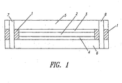
- FIG 1 a schematic cross-sectional representative view of a fuel cell assembly in a SPE fuel cell stack is presented. For simplicity, only one MEA is shown along with its adjacent flow field plates. A typical stack would comprise many such MEAs separated by shared bipolar flow field plates in which the fuel and oxidant flow fields would appear on opposite surfaces of each shared plate.
- the MEA includes solid polymer electrolyte membrane 2 sandwiched between and bonded to cathode 3 and anode 4.
- Flow field plates 5 and 6 are positioned adjacent cathode 3 and anode 4 and provide oxidant and fuel thereto, respectively.
- Internal manifolds 7 and 8 are direct fuel and oxidant to and from flow field plates 5 and 6.
- Seal 1 represents a set of seals that prevent mixing of the fuel and oxidant on either side of the MEA, that help form and isolate internal manifolds 7 and 8, and that prevent leaks to the external environment. (Fluid distribution features connecting the manifolds to the respective flow fields in plates 5 and 6 are not shown in this schematic.) Seal 1 is typically compressed between plates 5 and 6.
- the set of seals represented by seal 1 can conveniently be combined and attached to the subassembly consisting of membrane 2 bonded to cathode 3 and anode 4 in order to form a unitary MEA with integrated seal.
- Figure 2a shows a plan view of a representative MEA comprising an improved integrated seal.
- surface 10 of the cathode of the MEA is visible.
- the integrated seal is formed in a single molding operation and includes edge seal 11 (which is impregnated into the pores at the edge of the cathode around the entire periphery of the cathode) and internal manifold seals 12 at each end of the MEA.
- edge seal 11 which is impregnated into the pores at the edge of the cathode around the entire periphery of the cathode
- internal manifold seals 12 at each end of the MEA.
- there are three internal manifolds 13 (for fuel, oxidant, and coolant) at each end of the MEA one set for fluid supply and one set for fluid exhaust).
- edge seal 11 A cross-sectional view of edge seal 11 is visible in Figure 2b which shows the profile along section A-A of Figure 2a. The design and features of edge seal 11 are described in more detail below.
- a cross-sectional view of internal manifold seals 12 is visible in Figure 2c which shows the profile along section B-B of Figure 2a. As shown, manifold seals 12 have a similar cross-sectional shape as the sealing element in edge seal 11. However, other alternative shapes may be employed if desired.
- Figure 3c shows a magnified cross-sectional view of the edge seal of Figure 2b along with portions of flow field plates 25 and 26 that would be employed adjacent the MEA in the construction of a cell stack.
- edge seal 21c is shown prior to compression between plates 25 and 26.
- two prior art edge seal designs for a MEA with integrated seal are shown in Figures 3a and 3b respectively.
- the MEA subassemblies in each of Figures 3a, b; and c are the same and comprise a laminate of electrolyte membrane 22, cathode electrode 23; and anode electrode 24.
- the material used to form the edge seal is impregnated into the pores of both electrodes 23 and 24 in regions 27.
- the impregnated material saturates the pores thereby preventing gas from leaking around electrolyte membrane 22 at the edge of electrodes 23 and 24.
- the impregnated material serves to anchor edge seals 21a, b, and c to their respective MEA subassemblies.
- it is advantageous for the molded edge seal to extend outside the pores of the electrode and to encapsulate the entire end of the MEA subassembly as shown in each of these Figures.
- a sealing element 28a is located on either side of the MEA subassembly and is connected to the material impregnated into the pores in regions 27. (The impregnating of the pores and the formation of sealing element 28a are accomplished at the same time in a single molding step.) When compressed between two flow field plates (not shown), sealing element 28 is pinched between electrolyte membrane 22 and the flow field plates, thereby effecting a seal. While a satisfactory seal may be made in this fashion, sealing element 28a typically cannot be overly compressed ( e.g. , more than about 30%) without the resulting stress causing material failure at the interfaces with the electrodes.
- sealing element 28a detaches from the electrodes 23, 24 and creates a leak path around the electrolyte membrane 22.
- the second prior art edge seal 21b. in Figure 3b has two sealing elements 28b and 29b.
- Sealing element 28b is formed similarly to sealing element 28a in Figure 3a and functions in a like manner.
- Sealing element 29b is formed adjacent to the edge of the MEA subassembly and, as shown, is about as thick as sealing element 28b.
- sealing element 29b When compressed between two flow field plates (not shown), sealing element 29b provides a secondary seal between the two flow field plates thereby preventing external leaks from the fuel cell. If properly restrained, sealing element 29b may be able to maintain a suitable secondary seal even if substantially compressed. Again, however, if sealing element 28a is overly compressed, failure may occur at the interface with electrodes 23 and 24, resulting in a leak path around the electrolyte membrane.
- sealing element 28b and 29b are nominally the same (i.e., same reduction in thickness)
- the relative compression (i.e., % decrease in thickness) of each of the two separate sides of sealing element 28b is much greater than that of sealing element 29b.
- edge seal 21c shown in Figure 3c is designed such that sealing element 29c can be substantially compressed without there being undue strain at the interface with the impregnated electrodes.
- Edge seal 21c has an inboard pad 28c that, like the preceding prior art designs, is connected to the material impregnated into the electrode pores (regions 27) and is part of the material encapsulating the end of the MEA subassembly. Inboard pad 28c does not function as a seal but does strengthen the bond between edge seal 21c and the MEA subassembly. Inboard pad 28c also serves to limit the compression on sealing element 29c in the event that the assembly is compressed beyond nominal.
- inboard pad 28c is thus greater than the MEA subassembly, but is such that, when the whole assembly is compressed between flow field plates 25 and 26 to its nominal thickness, the stress within pad 28c is less than that which would cause it to detach from the electrodes, i.e., is less than its shear stress limit at the electrode interface.
- This can be accomplished, for instance, by having inboard pad 28c just contact adjacent flow field plates 25 and 26 ( i.e. , zero compression) when the assembly is at its nominal thickness. Should the assembly be compressed to less than this nominal thickness however, inboard pad 28c serves to limit the compression on sealing element 29c but of course then starts to be subjected to some compressive stress.
- inboard pad 28c can take some significant compressive stress (and hence the assembly can tolerate some significant variation in component thickness) without exceeding the shear stress limit at the electrode interface.
- Sealing element 29c is substantially thicker than inboard pad 28c and is significantly compressed (e.g ., >30% compression, more than typical industrial seals) when the whole assembly is compressed to its nominal thickness in a fuel cell stack.
- the stress within sealing element 29c may be significantly greater than that which would cause inboard pad 28c to detach from electrodes 23 and 24. However, as long as this stress is not transmitted through to inboard pad 28c, such interface damage should not occur.
- Flexible coupling 30c is thus provided between inboard pad 28c and sealing element 29c in order to isolate the former from stress in the latter.
- the thickness of flexible coupling 28c is chosen such that there will a gap between it and adjacent flow field plates 25 and 26 when the whole assembly is compressed to its nominal thickness. As such, in the event that the assembly is compressed to less than its nominal thickness, the material forming flexible coupling 28c could be deformed further and there would be some empty space around for it to flow into, instead of transferring stress therethrough to inboard pad 28c.
- edge seal 21c in Figure 3c allows for greater tolerances to be accepted in the associated fuel cell components without compromising reliability of the seals.
- typical MEA subassemblies may nominally be about 400-500 micrometers in thickness.
- the thickness of the flow field plates and hence also the sealing elements is gradually being reduced.
- the sealing elements are typically seated in a groove in a flow field plate and of course the possible depth of this groove gets reduced along with the thickness of the plate.
- A. typical prior art sealing element like element 29b may now nominally be about 900 micrometers in thickness when compressed.
- sealing elements 28a or 28b may only be about 250 micrometers thick (from electrode interface to flow field plate) when compressed. Consequently, component thickness tolerances of as little as ⁇ 50 micrometers can be unacceptable in such a situation.
- sealing element 28b is about 400 and 250 micrometers thick when uncompressed and compressed respectively (about 38% compression).
- the possible range of compression in sealing element 28b would be about 14-56%. At the upper limit, sealing element 28b may detach from the MEA subassembly and thus would be unacceptable.
- the total possible variation would be ⁇ 200 micrometer for sealing element 29b ( ⁇ 50 micrometers for each seal groove, molded seal and MEA thickness), with a resulting possible wide range of compression of about 9-40%.
- a sealing element 29c of about 1850 micrometers when uncompressed (about 42% compression) and an inboard pad 28c thickness of about 340 micrometers (0% compression).
- the possible range of compression in inboard pad 28c would then be about 0-25% while in sealing element 29c it would be about 32-51%.
- the embodiment of Figure 3c includes several other advantageous features.
- Chamfers 31c are provided on the edges of inboard pad 28c at the interfaces with electrodes 23 and 24. This reduces the shear stress concentration at this interface thereby reducing the risk of material failure.
- Inboard pad 28c also may be used as an alignment feature when assembling a cell stack. For instance, pad 28c can be aligned against surfaces 32 and 33 of flow field plates 25 and 26 during assembly, thereby centering the MEA assembly between the plates.
- sealing element 29c in Figure 3c is not a simple circle but instead is described by two, slightly vertically offset circles, thereby increasing its height/width aspect ratio. As the shape changes under a small amount of compression, the circles effectively become concentric. Thus, when compared to a sealing element with a circular cross-section, this offset effectively allows for a small amount of applied "precompressive" load without affecting the stability of the seal. In turn, the volume occupied by the seal can be reduced.
- Edge seal 21c may also include insulating tab 34 which is useful for electrically insulating flow field plate 25 from adjacent plate 26 and also for protecting sealing element 29c from damage during stack assembly. Like inboard pad 28c, insulating tab 34 also can serve to limit the compression applied to sealing element 29c.
- flow field plates 25 and 26 desirably include retaining walls 35 which can be used to prevent edge seal 21 c from blowing out in the event of an overpressurization within the fuel cell stack. When pressure conditions return to normal within the stack, edge seal 21 c may then reseat, thereby resealing the cell.
- Edge seal 21c may be cast in place, in one step, on a suitably sized, flush-cut MEA subassembly using liquid injection molding (LIM) techniques and a suitable polymerizable liquid sealant material.
- LIM liquid injection molding
- the presence of inboard pad 28c in the edge seal design assists in the LIM process since the cavity it occupies in the mold initially provides an easy path for the liquid sealant material to access and fill regions 27 in electrodes 23 and 24.
- Elastomer materials that are suitable for sealing functions when under significant compression, e.g ., >30%, are generally suitable as materials for edge seal 21c.
- the materials must also be chemically compatible with the environment within the SPE fuel cell.
- a low viscosity liquid silicone elastomer may have suitable mechanical properties for this application. When polymerized, certain such silicones are characterized by a Shore A hardness of about 40 and a simple tension modulus of about 0.2 MPa at 40% strain.
- Other elastomers which are chemically compatible and have similar mechanical characteristics may however be contemplated for use instead.
- certain grades of EPDM (ethylene-propylene-diene terpolymer) or fluoroelastomers may be suitable as well.
- an important parameter to determine is the interface stress limit for the seal material and electrode combination to be employed.
- This interface stress limit is a function of the pore and surface structure of the electrodes as well as the type of seal material employed.
- appropriate dimensions can be readily calculated for the various structures making up the edge seal in order to suit the given MEA subassembly.
- the inboard pad should be sized such that the interface stress limit is not exceeded when the whole MEA assembly is at the upper compression limit.
- the sealing element is sized to remain significantly compressed, and hence to seal reliably, over the entire possible compression range.
- the interface stress limit is readily determined empirically.
- a simple method involves preparing an elastomer/electrode sample where an elastomer "pad” with a square profile of known size is cast onto an electrode similar to that employed in the desired MEA subassembly.
- the cast elastomer "pad” additionally impregnates and fully saturates the pores of the electrode.
- the sample "pad” is then compressed between flat plates until it visually shears from the electrode. (In the case of a low viscosity silicone on a carbon fiber paper electrode, the appearance of the interface changes from black to silver when it shears off.)
- the values from this empirical test can then be used to calculate the interface stress limit and the compression limit for a pad of any shape.
- the interface shear stress limit for this seal material/electrode combination was determined empirically as described above.
- a silicone sample (4mm square in section and 2 mm high) was cast into/onto a TGP-60 carbon fiber paper layer. Under load, the sample sheared at the interface with the carbon fiber paper at 25% compression. This corresponded to a maximum stress at the interface (or interface shear stress limit) of 1.2 MPa.
- a comparative embodiment was similar to that depicted in Figure 3b.
- the MEA subassembly was about 440 micrometers thick when compressed.
- the height of sealing element 28b on each side of the MEA subassembly outside of the electrodes was about 390 micrometers.
- Sealing element 29b was about 1220 micrometers thick.
- An inventive embodiment was similar to that depicted in Figure 3b.
- the MEA subassembly was also about 440 micrometers thick.
- the height of each side of inboard pad 28c outside of the electrodes was 340 micrometers thick.
- Sealing element 29c was about 1850 micrometers thick and had a cross-sectional shape described by two circles vertically offset by 0.35 mm.
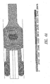
- FIGS 4a and 4b show the strain profiles of the comparative and inventive edge seals, respectively, when nominally compressed.
- the nominal compressed thickness of edge seal 21b was about 920 micrometers.
- the nominal compressed thickness of edge seal 21c was about 1120 micrometers.
- the bar chart at the bottom indicates the amount of strain (for instance, the dark solid fill indicates the lowest strain).
- sealing element 28b is under substantial strain while sealing element 29b is only moderately strained.
- inboard pad 28c is virtually unstrained while sealing element 29c is under substantial strain.
- a MEA with integrated edge seal I shows significant improvements over a MEA with edge seal C.
Landscapes
- Life Sciences & Earth Sciences (AREA)
- Engineering & Computer Science (AREA)
- Manufacturing & Machinery (AREA)
- Sustainable Development (AREA)
- Sustainable Energy (AREA)
- Chemical & Material Sciences (AREA)
- Chemical Kinetics & Catalysis (AREA)
- Electrochemistry (AREA)
- General Chemical & Material Sciences (AREA)
- Fuel Cell (AREA)
- Wire Bonding (AREA)
- Measurement Of Radiation (AREA)
- Hybrid Cells (AREA)
Claims (17)
- Pile à combustible à électrolyte polymère solide comprenant deux plaques et un assemblage d'électrodes à membrane comprenant un joint intégré, dans laquelle l'assemblage d'électrodes à membrane est comprimé à une épaisseur nominale entre les deux plaques, et dans laquelle l'assemblage d'électrodes à membrane comprend :un sous-assemblage d'électrodes à membrane comprimé entre les deux plaques, le sous-assemblage d'électrodes à membrane comprenant un électrolyte à membrane, une électrode de type cathode poreuse et une électrode de type anode poreuse, dans lequel ledit sous-assemblage d'électrodes à membrane est plan et comprend deux surfaces majeures ; etun joint de bord constitué d'un matériau d'étanchéité et comprimé entre les deux plaques, le joint de bord comprenant :a) un tampon intérieur adjacent aux deux surfaces majeures aux bords du sous-assemblage d'électrodes à membrane dans lequel le tampon sature les pores aux bords des électrodes à la périphérie du sous-assemblage d'électrodes à membrane, et dans lequel le tampon est plus épais que le sous-assemblage d'électrodes à membrane au moins aux bords et l'épaisseur du tampon est telle que la contrainte sur le tampon est inférieure à la limite de contrainte à l'interface des électrodes pour le matériau d'étanchéité ;b) un élément de couplage flexible adjacent au tampon intérieur et au bord du sous-assemblage d'électrodes à membrane dans lequel l'épaisseur de l'élément de couplage est inférieure à celle du tampon intérieur et est telle qu'il existe un espace entre chacune des deux plaques et l'élément de couplage ; etc) un élément d'étanchéité adjacent à l'élément de couplage flexible et comprimé entre les deux plaques pour former un joint, dans lequel l'épaisseur de l'élément d'étanchéité est supérieure à celle du tampon intérieur et est telle que l'élément d'étanchéité est plus comprimé que le tampon intérieur.
- Pile à combustible selon la revendication 1, dans laquelle le tampon intérieur est comprimé à moins d'environ 25 %.
- Pile à combustible selon la revendication 1, dans laquelle l'élément d'étanchéité est comprimé à plus de 30 %.
- Pile à combustible selon la revendication 1, dans laquelle le matériau d'étanchéité est un élastomère.
- Pile à combustible selon la revendication 4, dans laquelle l'élastomère est une silicone caractérisée par une dureté Shore A d'environ 40 et par un module de tension simple d'environ 0,2 MPa sous une contrainte de 40 %.
- Pile à combustible selon la revendication 5, dans laquelle la limite de contrainte à l'interface des électrodes est de 1,2 MPa.
- Pile à combustible selon la revendication 4, dans laquelle l'élastomère est un terpolymère éthylène-propylène-diène.
- Pile à combustible selon la revendication 4, dans laquelle l'élastomère est un élastomère fluoré.
- Pile à combustible selon la revendication 1, dans laquelle les électrodes de type cathode poreuse et anode poreuse comprennent un papier de fibres de carbone.
- Pile à combustible selon la revendication 1, dans laquelle la forme de l'élément d'étanchéité est décrite par deux cercles décalés perpendiculaires aux surfaces majeures du sous-assemblage d'électrodes à membrane.
- Pile à combustible selon la revendication 1, dans laquelle le tampon intérieur comprend un chanfrein adjacent à chaque surface majeure de l'assemblage d'électrodes à membrane.
- Pile à combustible selon la revendication 1, comprenant un tampon isolant adjacent à l'élément d'étanchéité.
- Pile à combustible à électrolyte polymère solide comprenant deux plaques et un assemblage d'électrodes à membrane comprenant un joint intégré, dans laquelle l'assemblage d'électrodes à membrane est comprimé à une épaisseur nominale entre les deux plaques, et dans laquelle l'assemblage d'électrodes à membrane comprend :un sous-assemblage d'électrodes à membrane comprimé entre les deux plaques, le sous-assemblage d'électrodes à membrane comprenant un électrolyte à membrane, une électrode de type cathode poreuse et une électrode de type anode poreuse, dans lequel le sous-assemblage d'électrodes à membrane est plan et comprend deux surfaces majeures ; etun joint de bord constitué d'un matériau d'étanchéité et comprimé entre les deux plaques, le joint de bord comprenant :dans laquelle l'élément de couplage flexible isole le tampon intérieur d'une contrainte provenant de l'élément d'étanchéité.a) un tampon intérieur adjacent aux deux surfaces majeures aux bords du sous-assemblage d'électrodes à membrane dans lequel le tampon sature les pores aux bords des électrodes à la périphérie du sous-assemblage d'électrodes à membrane, et dans lequel le tampon est plus épais que le sous-assemblage d'électrodes à membrane au moins aux bords et l'épaisseur du tampon est telle que la contrainte sur le tampon est insuffisante pour cisailler le tampon du sous-assemblage d'électrodes à membrane saturé ;b) un élément de couplage flexible adjacent au tampon intérieur et au bord du sous-assemblage d'électrodes à membrane dans lequel l'épaisseur de l'élément de couplage est inférieure à celle du tampon intérieur ; etc) un élément d'étanchéité adjacent à l'élément de couplage flexible et comprimé entre les deux plaques, dans lequel l'épaisseur de l'élément d'étanchéité est supérieure à celle du tampon intérieur et est telle que l'élément d'étanchéité est suffisamment comprimé pour réaliser un joint,
- Pile à combustible selon la revendication 11, dans laquelle les plaques sont des plaques de champ d'écoulement.
- Pile à combustible selon la revendication 14, dans laquelle chaque plaque de champ d'écoulement comprend une caractéristique d'alignement pour un alignement avec les chanfreins sur le tampon intérieur.
- Pile à combustible selon la revendication 14, dans laquelle chaque plaque de champ d'écoulement comprend une paroi de maintien pour maintenir l'élément d'étanchéité.
- Procédé de fabrication d'une pile à combustible à électrolyte polymère solide comprenant deux plaques et un assemblage d'électrodes à membrane comprenant un joint intégré, dans laquelle l'assemblage d'électrodes à membrane est comprimé à une épaisseur nominale entre les deux plaques, le procédé comprenant :la fourniture d'un sous-assemblage d'électrodes à membrane comprenant un électrolyte à membrane, une électrode de type cathode poreuse et une électrode de type anode poreuse, dans lequel le sous-assemblage d'électrodes à membrane est plan et comprend deux surfaces majeures ;la formation d'un joint de bord constitué d'un matériau d'étanchéité sur le bord du sous-assemblage d'électrodes à membrane pour former l'assemblage d'électrodes à membrane, dans lequel le joint de bord comprend :a) un tampon intérieur adjacent aux deux surfaces majeures aux bords du sous-assemblage d'électrodes à membrane dans lequel le tampon sature les pores aux bords des électrodes à la périphérie du sous-assemblage d'électrodes à membrane, et dans lequel le tampon est plus épais que le sous-assemblage d'électrodes à membrane au moins aux bords et l'épaisseur du tampon est telle que la contrainte sur le tampon est inférieure à la limite de contrainte à l'interface des électrodes pour le matériau d'étanchéité lorsque l'assemblage d'électrodes à membrane est comprimé à une épaisseur nominale ;b) un élément de couplage flexible adjacent au tampon intérieur et au bord du sous-assemblage d'électrodes à membrane dans lequel l'épaisseur de l'élément de couplage est inférieure à celle du tampon intérieur et est telle qu'il existe un espace entre chacune des deux plaques et l'élément de couplage lorsque l'assemblage d'électrodes à membrane est comprimé à une épaisseur nominale ; etc) un élément d'étanchéité adjacent à l'élément de couplage flexible, dans lequel l'épaisseur de l'élément d'étanchéité est supérieure à celle du tampon intérieur et est telle que l'élément d'étanchéité est plus comprimé que le tampon intérieur lorsque l'assemblage d'électrodes à membrane est comprimé à une épaisseur nominale ; etla compression de l'assemblage d'électrodes à membrane à une épaisseur nominale entre les deux plaques de telle sorte que l'élément d'étanchéité est comprimé entre les deux plaques pour former un joint.
Applications Claiming Priority (2)
| Application Number | Priority Date | Filing Date | Title |
|---|---|---|---|
| US10/395,874 US7070876B2 (en) | 2003-03-24 | 2003-03-24 | Membrane electrode assembly with integrated seal |
| PCT/CA2004/000388 WO2004102721A2 (fr) | 2003-03-24 | 2004-03-15 | Ensemble electrode a membrane avec joint integre |
Publications (2)
| Publication Number | Publication Date |
|---|---|
| EP1614181A2 EP1614181A2 (fr) | 2006-01-11 |
| EP1614181B1 true EP1614181B1 (fr) | 2006-07-12 |
Family
ID=32988670
Family Applications (1)
| Application Number | Title | Priority Date | Filing Date |
|---|---|---|---|
| EP04760761A Expired - Lifetime EP1614181B1 (fr) | 2003-03-24 | 2004-03-15 | Ensemble electrode a membrane avec joint integre |
Country Status (7)
| Country | Link |
|---|---|
| US (2) | US7070876B2 (fr) |
| EP (1) | EP1614181B1 (fr) |
| JP (1) | JP4742043B2 (fr) |
| AT (1) | ATE333150T1 (fr) |
| CA (1) | CA2519951A1 (fr) |
| DE (1) | DE602004001520T2 (fr) |
| WO (1) | WO2004102721A2 (fr) |
Cited By (2)
| Publication number | Priority date | Publication date | Assignee | Title |
|---|---|---|---|---|
| WO2010115605A1 (fr) | 2009-04-08 | 2010-10-14 | Daimler Ag | Pile à combustible, empilement de piles à combustible et procédé d'étanchéification d'une pile à combustible |
| CN111129539A (zh) * | 2019-12-28 | 2020-05-08 | 一汽解放汽车有限公司 | 一种燃料电池膜电极密封装置及其制备方法 |
Families Citing this family (55)
| Publication number | Priority date | Publication date | Assignee | Title |
|---|---|---|---|---|
| US7645543B2 (en) * | 2002-10-15 | 2010-01-12 | Polyplus Battery Company | Active metal/aqueous electrochemical cells and systems |
| US7670709B2 (en) * | 2002-12-31 | 2010-03-02 | Freudenberg-Nok General Partnership | Fuel cell seal with integral bridge |
| CA2464204C (fr) * | 2003-04-14 | 2009-08-11 | Matsushita Electric Industrial Co., Ltd. | Pile a combustible a electrolyte polymere et separateur conducteur connexe |
| US7655339B1 (en) * | 2003-06-06 | 2010-02-02 | Dana Automotive Systems Group, Llc | Molded fuel cell plates with seals |
| US7282295B2 (en) | 2004-02-06 | 2007-10-16 | Polyplus Battery Company | Protected active metal electrode and battery cell structures with non-aqueous interlayer architecture |
| US7687180B2 (en) * | 2004-06-30 | 2010-03-30 | Freudenberg-Nok General Partnership | Overmolded support plate for fuel cell |
| WO2006071234A1 (fr) * | 2004-12-28 | 2006-07-06 | Utc Fuel Cells, Llc | Structure d'ensemble membrane / electrodes (mea) contenant une couche catalysee |
| JP2006236957A (ja) * | 2005-01-31 | 2006-09-07 | Uchiyama Mfg Corp | 燃料電池用構成部材 |
| US7582378B2 (en) * | 2005-06-30 | 2009-09-01 | Freudenberg-Nok General Partnership | Fuel cell seal and plate features |
| US20070003821A1 (en) | 2005-06-30 | 2007-01-04 | Freudenberg-Nok General Partnership | Integrally molded gasket for a fuel cell assembly |
| US8003273B2 (en) * | 2005-07-13 | 2011-08-23 | Panasonic Corporation | Polymer electrolyte fuel cell and fuel cell sealing member for the same |
| JP5062389B2 (ja) * | 2005-07-15 | 2012-10-31 | Nok株式会社 | 燃料電池およびその製造方法 |
| EP1917689B1 (fr) * | 2005-08-09 | 2017-11-08 | Polyplus Battery Company | Structures de scellement élastiques pour anodes à métal actif protégées |
| US8404388B2 (en) | 2005-08-09 | 2013-03-26 | Polyplus Battery Company | Compliant seal structures for protected active metal anodes |
| US8048570B2 (en) * | 2005-08-09 | 2011-11-01 | Polyplus Battery Company | Compliant seal structures for protected active metal anodes |
| US8129052B2 (en) | 2005-09-02 | 2012-03-06 | Polyplus Battery Company | Polymer adhesive seals for protected anode architectures |
| US20070042255A1 (en) * | 2005-08-19 | 2007-02-22 | Seungsoo Jung | Seal for fuel cell |
| EP1923943B1 (fr) * | 2005-09-06 | 2013-07-17 | NOK Corporation | Composant de constitution d'une pile a combustible |
| US8546045B2 (en) * | 2005-09-19 | 2013-10-01 | 3M Innovative Properties Company | Gasketed subassembly for use in fuel cells including replicated structures |
| US8497046B2 (en) * | 2005-12-22 | 2013-07-30 | Nissan Motor Co., Ltd. | Sealing structure for fuel cell |
| EP1826849A1 (fr) * | 2006-02-24 | 2007-08-29 | Auto-Juntas, S.A. Unipersonal | Assemblage membrane-électrode ayant une structure d'étanchéité renforcée |
| JP5011764B2 (ja) * | 2006-03-14 | 2012-08-29 | トヨタ自動車株式会社 | シール一体型膜電極接合体製造技術 |
| FI20060319A7 (fi) * | 2006-03-31 | 2007-10-01 | Stora Enso Oyj | Menetelmä pakkausten sulkemiseksi ja pakkaus |
| JP5087863B2 (ja) * | 2006-06-09 | 2012-12-05 | トヨタ自動車株式会社 | 燃料電池 |
| US20080050639A1 (en) * | 2006-08-23 | 2008-02-28 | Michael Medina | Bipolar flow field plate assembly and method of making the same |
| US20080076005A1 (en) * | 2006-09-22 | 2008-03-27 | Michel Bitton | Fuel cell fluid distribution system |
| US9496578B2 (en) * | 2007-02-20 | 2016-11-15 | Freudenberg-Nok General Partnership | Gas diffusion layer with integrated seal for use in a fuel cell |
| EE05447B1 (et) * | 2007-04-30 | 2011-08-15 | Ilt�enko Valeri | Kahekambrilise koaksiaalse elektrolseri protsessiseadis |
| US20090004543A1 (en) * | 2007-06-27 | 2009-01-01 | Seungsoo Jung | Membrane electrode assemblies for fuel cells and methods of making |
| JP5396029B2 (ja) * | 2008-02-21 | 2014-01-22 | 東海ゴム工業株式会社 | 燃料電池用セルおよび燃料電池および燃料電池用セルの製造方法 |
| JP4416038B2 (ja) | 2008-02-21 | 2010-02-17 | トヨタ自動車株式会社 | 燃料電池 |
| DE102008013038A1 (de) * | 2008-03-06 | 2009-09-10 | Carl Freudenberg Kg | Dichtung für eine Brennstoffzelle |
| CN101673833B (zh) * | 2009-09-23 | 2011-08-24 | 新源动力股份有限公司 | 一种带密封框的膜电极一体化组件及其制备方法 |
| US10044047B2 (en) * | 2010-01-05 | 2018-08-07 | Panasonic Intellectual Property Management Co., Ltd. | Electrode-membrane-frame assembly, method for producing the same, and fuel cell |
| GB201012980D0 (en) * | 2010-08-03 | 2010-09-15 | Johnson Matthey Plc | Membrane |
| EP2668689B1 (fr) | 2011-01-28 | 2017-06-14 | Audi AG | Joint de pile à combustible |
| DE102011051309B4 (de) * | 2011-06-24 | 2013-01-17 | Eisenhuth Gmbh & Co. Kg | Membranelektrodeneinheit für eine Brennstoffzelle, Gießform und Verfahren zum Herstellen der Membranelektrodeneinheit |
| DE102012102750B4 (de) * | 2012-03-29 | 2021-04-22 | Deutsches Zentrum für Luft- und Raumfahrt e.V. | Brennstoffzellenelement und Brennstoffzellenvorrichtung |
| US8921009B2 (en) | 2012-07-30 | 2014-12-30 | Zephyros, Inc. | Process for fuel cell formation |
| CN104520397B (zh) | 2012-07-30 | 2017-06-13 | 泽费罗斯股份有限公司 | 粘合剂沉积用方法和设备 |
| US9905860B2 (en) | 2013-06-28 | 2018-02-27 | Polyplus Battery Company | Water activated battery system having enhanced start-up behavior |
| DE102013014077A1 (de) | 2013-08-27 | 2015-03-05 | Elcomax Gmbh | Verfahren zur Herstellung einer Membran-Elektroden-Einheit mit umlaufender Dichtung sowie Membran-Elektroden-Einheit |
| DE102013014083A1 (de) | 2013-08-27 | 2015-03-05 | Elcomax Gmbh | Verfahren zur Herstellung einer Membran-Elektroden-Einheit mit umlaufender Dichtung sowie Membran-Elektroden-Einheit |
| KR101520345B1 (ko) * | 2013-12-03 | 2015-05-15 | (주)오렌지파워 | 입체형 전극 어셈블리 및 이의 제조 방법 |
| US9789682B2 (en) * | 2014-05-19 | 2017-10-17 | Nissan Motor Co., Ltd. | Metal mask and screen printing apparatus |
| JP6383203B2 (ja) * | 2014-07-25 | 2018-08-29 | Nok株式会社 | プレート一体ガスケットの製造方法 |
| WO2016114426A1 (fr) * | 2015-01-15 | 2016-07-21 | (주)오렌지파워 | Ensemble électrode tridimentionnel et son procédé de fabrication |
| CN107710482B (zh) * | 2015-06-15 | 2020-11-17 | 森村索福克科技股份有限公司 | 燃料电池堆和燃料电池堆的制造方法 |
| DE102015218757B4 (de) * | 2015-09-29 | 2025-06-12 | Audi Ag | Brennstoffzellenstapel und Brennstoffzellensystem |
| DE102015221158A1 (de) * | 2015-10-29 | 2017-05-04 | Volkswagen Aktiengesellschaft | Verfahren zum Herstellen einer Membran-Elektroden-Einheit und Membran-Elektroden-Einheit |
| JP7128812B2 (ja) * | 2016-11-09 | 2022-08-31 | 大連融科儲能技術発展有限公司 | フロー電池の電極構造、フロー電池電堆及びフロー電池電堆の密封構造 |
| DE102017101954A1 (de) * | 2017-02-01 | 2018-08-02 | Audi Ag | Membran-Elektroden-Anordnung und Brennstoffzellenstapel |
| DE102017214983A1 (de) | 2017-08-28 | 2019-02-28 | Audi Ag | Membran-Elektroden-Einheit mit einer Dichtungsanordnung, Brennstoffzelle sowie Brennstoffzellenstapel |
| CN117813708A (zh) | 2021-12-23 | 2024-04-02 | 住友理工株式会社 | 燃料电池单元组件及其制造方法 |
| CN119252966A (zh) * | 2024-09-14 | 2025-01-03 | 鸿基创能科技(佛山)有限公司 | 一种单边框膜电极的封装方法及封装结构 |
Family Cites Families (13)
| Publication number | Priority date | Publication date | Assignee | Title |
|---|---|---|---|---|
| DE19703214C2 (de) | 1997-01-29 | 2003-10-30 | Proton Motor Fuel Cell Gmbh | Membran-Elektrodeneinheit mit integriertem Dichtrand und Verfahren zu ihrer Herstellung |
| ATE216138T1 (de) * | 1997-07-16 | 2002-04-15 | Ballard Power Systems | Elastische dichtung für eine membranelektrodenanordnung in einer elektrochemischen brennstoffzelle und herstellungsverfahren dafür |
| JPH11219714A (ja) * | 1998-02-03 | 1999-08-10 | Matsushita Electric Ind Co Ltd | 燃料電池 |
| US6020083A (en) | 1998-10-30 | 2000-02-01 | International Fuel Cells Llc | Membrane electrode assembly for PEM fuel cell |
| AU3234200A (en) | 1999-03-10 | 2000-09-28 | Flexfab Horizons International, Inc. | Fuel cell gasket assembly and method of assembling fuel cells |
| WO2000064995A1 (fr) * | 1999-04-27 | 2000-11-02 | Nok Corporation | Joint d'etancheite |
| US6231053B1 (en) | 1999-06-11 | 2001-05-15 | Nok Corporation | Gasket for fuel cell |
| WO2001017048A1 (fr) * | 1999-09-01 | 2001-03-08 | Nok Corporation | Cellule electrochimique |
| JP3866050B2 (ja) * | 2000-05-02 | 2007-01-10 | 本田技研工業株式会社 | 燃料電池 |
| JP3542550B2 (ja) | 2000-07-19 | 2004-07-14 | 本田技研工業株式会社 | 燃料電池用シールの成形方法 |
| GB0112021D0 (en) | 2001-05-17 | 2001-07-11 | Johnson Matthey Plc | Substrate |
| US20030224237A1 (en) | 2002-05-30 | 2003-12-04 | Vanderleeden Olen R. | Membrane electrode assembly for an electrochemical fuel cell |
| US6989214B2 (en) * | 2002-11-15 | 2006-01-24 | 3M Innovative Properties Company | Unitized fuel cell assembly |
-
2003
- 2003-03-24 US US10/395,874 patent/US7070876B2/en not_active Expired - Lifetime
-
2004
- 2004-03-15 DE DE602004001520T patent/DE602004001520T2/de not_active Expired - Lifetime
- 2004-03-15 AT AT04760761T patent/ATE333150T1/de not_active IP Right Cessation
- 2004-03-15 EP EP04760761A patent/EP1614181B1/fr not_active Expired - Lifetime
- 2004-03-15 WO PCT/CA2004/000388 patent/WO2004102721A2/fr not_active Ceased
- 2004-03-15 JP JP2006529481A patent/JP4742043B2/ja not_active Expired - Lifetime
- 2004-03-15 CA CA002519951A patent/CA2519951A1/fr not_active Abandoned
-
2006
- 2006-05-17 US US11/436,122 patent/US7722978B2/en not_active Expired - Lifetime
Cited By (4)
| Publication number | Priority date | Publication date | Assignee | Title |
|---|---|---|---|---|
| WO2010115605A1 (fr) | 2009-04-08 | 2010-10-14 | Daimler Ag | Pile à combustible, empilement de piles à combustible et procédé d'étanchéification d'une pile à combustible |
| DE102009016934A1 (de) | 2009-04-08 | 2010-10-14 | Daimler Ag | Brennstoffzelle, Brennstoffzellenstapel und Verfahren zum Abdichten einer Brennstoffzelle |
| CN111129539A (zh) * | 2019-12-28 | 2020-05-08 | 一汽解放汽车有限公司 | 一种燃料电池膜电极密封装置及其制备方法 |
| CN111129539B (zh) * | 2019-12-28 | 2021-05-28 | 一汽解放汽车有限公司 | 一种燃料电池膜电极密封装置及其制备方法 |
Also Published As
| Publication number | Publication date |
|---|---|
| EP1614181A2 (fr) | 2006-01-11 |
| WO2004102721A2 (fr) | 2004-11-25 |
| US7070876B2 (en) | 2006-07-04 |
| US20040191604A1 (en) | 2004-09-30 |
| DE602004001520D1 (de) | 2006-08-24 |
| US20060269819A1 (en) | 2006-11-30 |
| JP2006529049A (ja) | 2006-12-28 |
| WO2004102721A3 (fr) | 2005-02-03 |
| DE602004001520T2 (de) | 2007-02-22 |
| ATE333150T1 (de) | 2006-08-15 |
| US7722978B2 (en) | 2010-05-25 |
| CA2519951A1 (fr) | 2004-11-25 |
| JP4742043B2 (ja) | 2011-08-10 |
Similar Documents
| Publication | Publication Date | Title |
|---|---|---|
| EP1614181B1 (fr) | Ensemble electrode a membrane avec joint integre | |
| KR100876262B1 (ko) | 고체 고분자 전해질형 연료전지 | |
| EP2371020B1 (fr) | Joint pour pile à combustible à électrolyte polymère solide | |
| US6872485B2 (en) | Sealing structure for fuel cell | |
| US6261711B1 (en) | Sealing system for fuel cells | |
| EP2341573B1 (fr) | Structure d'étanchéité de pile à combustible | |
| US20110236786A1 (en) | Fuel cell | |
| US6844101B2 (en) | Separator with fluid distribution features for use with a membrane electrode assembly in a fuel cell | |
| US20090130519A1 (en) | Fuel cell | |
| EP1792359B1 (fr) | Ensemble electrode a membrane | |
| KR20180115266A (ko) | 비대칭 밀봉 섹션을 포함한 양극판, 그리고 상기 양극판을 포함한 연료 전지 스택 | |
| JP2009021217A (ja) | 燃料電池用の電極−膜−枠接合体およびその製造方法、並びに高分子電解質型燃料電池およびその製造方法 | |
| WO2006022758A1 (fr) | Support de diffusion enrobé de catalyseur à protection périphérique et assemblages électrode-membrane | |
| US20190252693A1 (en) | Fuel cell microseal and a method of manufacture thereof | |
| EP1932199B1 (fr) | Joint integre pour ensemble pile a combustible et assemblage de piles a combustible | |
| KR100572087B1 (ko) | 고분자 전해질형 연료전지 | |
| WO2007022464A2 (fr) | Joint pour pile à combustible | |
| US8911916B2 (en) | Fuel cell | |
| WO2009067617A1 (fr) | Ensemble de plaques de champ d'écoulement pour pile à combustible | |
| JP2012084468A (ja) | 固体電解質形燃料電池 | |
| CN116895780A (zh) | 增强型密封的燃料电池组件 | |
| JP2004363093A (ja) | 燃料電池およびその分解方法 | |
| US20070141438A1 (en) | Fuel cell stack |
Legal Events
| Date | Code | Title | Description |
|---|---|---|---|
| PUAI | Public reference made under article 153(3) epc to a published international application that has entered the european phase |
Free format text: ORIGINAL CODE: 0009012 |
|
| 17P | Request for examination filed |
Effective date: 20051010 |
|
| AK | Designated contracting states |
Kind code of ref document: A2 Designated state(s): AT BE BG CH CY CZ DE DK EE ES FI FR GB GR HU IE IT LI LU MC NL PL PT RO SE SI SK TR |
|
| AX | Request for extension of the european patent |
Extension state: AL LT LV MK |
|
| GRAP | Despatch of communication of intention to grant a patent |
Free format text: ORIGINAL CODE: EPIDOSNIGR1 |
|
| GRAS | Grant fee paid |
Free format text: ORIGINAL CODE: EPIDOSNIGR3 |
|
| GRAA | (expected) grant |
Free format text: ORIGINAL CODE: 0009210 |
|
| DAX | Request for extension of the european patent (deleted) | ||
| AK | Designated contracting states |
Kind code of ref document: B1 Designated state(s): AT BE BG CH CY CZ DE DK EE ES FI FR GB GR HU IE IT LI LU MC NL PL PT RO SE SI SK TR |
|
| PG25 | Lapsed in a contracting state [announced via postgrant information from national office to epo] |
Ref country code: IT Free format text: LAPSE BECAUSE OF FAILURE TO SUBMIT A TRANSLATION OF THE DESCRIPTION OR TO PAY THE FEE WITHIN THE PRESCRIBED TIME-LIMIT;WARNING: LAPSES OF ITALIAN PATENTS WITH EFFECTIVE DATE BEFORE 2007 MAY HAVE OCCURRED AT ANY TIME BEFORE 2007. THE CORRECT EFFECTIVE DATE MAY BE DIFFERENT FROM THE ONE RECORDED. Effective date: 20060712 Ref country code: RO Free format text: LAPSE BECAUSE OF FAILURE TO SUBMIT A TRANSLATION OF THE DESCRIPTION OR TO PAY THE FEE WITHIN THE PRESCRIBED TIME-LIMIT Effective date: 20060712 Ref country code: LI Free format text: LAPSE BECAUSE OF FAILURE TO SUBMIT A TRANSLATION OF THE DESCRIPTION OR TO PAY THE FEE WITHIN THE PRESCRIBED TIME-LIMIT Effective date: 20060712 Ref country code: BE Free format text: LAPSE BECAUSE OF FAILURE TO SUBMIT A TRANSLATION OF THE DESCRIPTION OR TO PAY THE FEE WITHIN THE PRESCRIBED TIME-LIMIT Effective date: 20060712 Ref country code: FI Free format text: LAPSE BECAUSE OF FAILURE TO SUBMIT A TRANSLATION OF THE DESCRIPTION OR TO PAY THE FEE WITHIN THE PRESCRIBED TIME-LIMIT Effective date: 20060712 Ref country code: CZ Free format text: LAPSE BECAUSE OF FAILURE TO SUBMIT A TRANSLATION OF THE DESCRIPTION OR TO PAY THE FEE WITHIN THE PRESCRIBED TIME-LIMIT Effective date: 20060712 Ref country code: AT Free format text: LAPSE BECAUSE OF FAILURE TO SUBMIT A TRANSLATION OF THE DESCRIPTION OR TO PAY THE FEE WITHIN THE PRESCRIBED TIME-LIMIT Effective date: 20060712 Ref country code: SI Free format text: LAPSE BECAUSE OF FAILURE TO SUBMIT A TRANSLATION OF THE DESCRIPTION OR TO PAY THE FEE WITHIN THE PRESCRIBED TIME-LIMIT Effective date: 20060712 Ref country code: CH Free format text: LAPSE BECAUSE OF FAILURE TO SUBMIT A TRANSLATION OF THE DESCRIPTION OR TO PAY THE FEE WITHIN THE PRESCRIBED TIME-LIMIT Effective date: 20060712 Ref country code: NL Free format text: LAPSE BECAUSE OF FAILURE TO SUBMIT A TRANSLATION OF THE DESCRIPTION OR TO PAY THE FEE WITHIN THE PRESCRIBED TIME-LIMIT Effective date: 20060712 Ref country code: PL Free format text: LAPSE BECAUSE OF FAILURE TO SUBMIT A TRANSLATION OF THE DESCRIPTION OR TO PAY THE FEE WITHIN THE PRESCRIBED TIME-LIMIT Effective date: 20060712 Ref country code: SK Free format text: LAPSE BECAUSE OF FAILURE TO SUBMIT A TRANSLATION OF THE DESCRIPTION OR TO PAY THE FEE WITHIN THE PRESCRIBED TIME-LIMIT Effective date: 20060712 |
|
| REG | Reference to a national code |
Ref country code: GB Ref legal event code: FG4D |
|
| REG | Reference to a national code |
Ref country code: CH Ref legal event code: EP |
|
| REG | Reference to a national code |
Ref country code: IE Ref legal event code: FG4D |
|
| REF | Corresponds to: |
Ref document number: 602004001520 Country of ref document: DE Date of ref document: 20060824 Kind code of ref document: P |
|
| PG25 | Lapsed in a contracting state [announced via postgrant information from national office to epo] |
Ref country code: SE Free format text: LAPSE BECAUSE OF FAILURE TO SUBMIT A TRANSLATION OF THE DESCRIPTION OR TO PAY THE FEE WITHIN THE PRESCRIBED TIME-LIMIT Effective date: 20061012 Ref country code: DK Free format text: LAPSE BECAUSE OF FAILURE TO SUBMIT A TRANSLATION OF THE DESCRIPTION OR TO PAY THE FEE WITHIN THE PRESCRIBED TIME-LIMIT Effective date: 20061012 Ref country code: BG Free format text: LAPSE BECAUSE OF FAILURE TO SUBMIT A TRANSLATION OF THE DESCRIPTION OR TO PAY THE FEE WITHIN THE PRESCRIBED TIME-LIMIT Effective date: 20061012 |
|
| PG25 | Lapsed in a contracting state [announced via postgrant information from national office to epo] |
Ref country code: ES Free format text: LAPSE BECAUSE OF FAILURE TO SUBMIT A TRANSLATION OF THE DESCRIPTION OR TO PAY THE FEE WITHIN THE PRESCRIBED TIME-LIMIT Effective date: 20061023 |
|
| RAP2 | Party data changed (patent owner data changed or rights of a patent transferred) |
Owner name: BALLARD POWER SYSTEMS INC. |
|
| PG25 | Lapsed in a contracting state [announced via postgrant information from national office to epo] |
Ref country code: PT Free format text: LAPSE BECAUSE OF FAILURE TO SUBMIT A TRANSLATION OF THE DESCRIPTION OR TO PAY THE FEE WITHIN THE PRESCRIBED TIME-LIMIT Effective date: 20061212 |
|
| NLV1 | Nl: lapsed or annulled due to failure to fulfill the requirements of art. 29p and 29m of the patents act | ||
| ET | Fr: translation filed | ||
| PLBE | No opposition filed within time limit |
Free format text: ORIGINAL CODE: 0009261 |
|
| STAA | Information on the status of an ep patent application or granted ep patent |
Free format text: STATUS: NO OPPOSITION FILED WITHIN TIME LIMIT |
|
| 26N | No opposition filed |
Effective date: 20070413 |
|
| REG | Reference to a national code |
Ref country code: FR Ref legal event code: ST Effective date: 20071130 |
|
| PG25 | Lapsed in a contracting state [announced via postgrant information from national office to epo] |
Ref country code: IE Free format text: LAPSE BECAUSE OF NON-PAYMENT OF DUE FEES Effective date: 20070315 Ref country code: MC Free format text: LAPSE BECAUSE OF NON-PAYMENT OF DUE FEES Effective date: 20070331 |
|
| PG25 | Lapsed in a contracting state [announced via postgrant information from national office to epo] |
Ref country code: GR Free format text: LAPSE BECAUSE OF FAILURE TO SUBMIT A TRANSLATION OF THE DESCRIPTION OR TO PAY THE FEE WITHIN THE PRESCRIBED TIME-LIMIT Effective date: 20061013 |
|
| PG25 | Lapsed in a contracting state [announced via postgrant information from national office to epo] |
Ref country code: EE Free format text: LAPSE BECAUSE OF FAILURE TO SUBMIT A TRANSLATION OF THE DESCRIPTION OR TO PAY THE FEE WITHIN THE PRESCRIBED TIME-LIMIT Effective date: 20060712 Ref country code: FR Free format text: LAPSE BECAUSE OF NON-PAYMENT OF DUE FEES Effective date: 20070402 |
|
| PG25 | Lapsed in a contracting state [announced via postgrant information from national office to epo] |
Ref country code: LU Free format text: LAPSE BECAUSE OF NON-PAYMENT OF DUE FEES Effective date: 20070315 Ref country code: CY Free format text: LAPSE BECAUSE OF FAILURE TO SUBMIT A TRANSLATION OF THE DESCRIPTION OR TO PAY THE FEE WITHIN THE PRESCRIBED TIME-LIMIT Effective date: 20060712 |
|
| PG25 | Lapsed in a contracting state [announced via postgrant information from national office to epo] |
Ref country code: HU Free format text: LAPSE BECAUSE OF FAILURE TO SUBMIT A TRANSLATION OF THE DESCRIPTION OR TO PAY THE FEE WITHIN THE PRESCRIBED TIME-LIMIT Effective date: 20070113 Ref country code: TR Free format text: LAPSE BECAUSE OF FAILURE TO SUBMIT A TRANSLATION OF THE DESCRIPTION OR TO PAY THE FEE WITHIN THE PRESCRIBED TIME-LIMIT Effective date: 20060712 |
|
| REG | Reference to a national code |
Ref country code: DE Ref legal event code: R082 Ref document number: 602004001520 Country of ref document: DE Representative=s name: WUESTHOFF & WUESTHOFF, PATENTANWAELTE PARTG MB, DE Ref country code: DE Ref legal event code: R081 Ref document number: 602004001520 Country of ref document: DE Owner name: BALLARD POWER SYSTEMS INC., BURNABY, CA Free format text: FORMER OWNERS: DAIMLER AG, 70327 STUTTGART, DE; FORD MOTOR CO., DEARBORN, MICH., US |
|
| PGFP | Annual fee paid to national office [announced via postgrant information from national office to epo] |
Ref country code: GB Payment date: 20230327 Year of fee payment: 20 Ref country code: DE Payment date: 20230329 Year of fee payment: 20 |
|
| P01 | Opt-out of the competence of the unified patent court (upc) registered |
Effective date: 20230526 |
|
| REG | Reference to a national code |
Ref country code: DE Ref legal event code: R071 Ref document number: 602004001520 Country of ref document: DE |
|
| REG | Reference to a national code |
Ref country code: GB Ref legal event code: PE20 Expiry date: 20240314 |
|
| PG25 | Lapsed in a contracting state [announced via postgrant information from national office to epo] |
Ref country code: GB Free format text: LAPSE BECAUSE OF EXPIRATION OF PROTECTION Effective date: 20240314 |