EP1614340B1 - Hélice transporteuse transversale pour dispositif de récolte - Google Patents
Hélice transporteuse transversale pour dispositif de récolte Download PDFInfo
- Publication number
- EP1614340B1 EP1614340B1 EP05105263A EP05105263A EP1614340B1 EP 1614340 B1 EP1614340 B1 EP 1614340B1 EP 05105263 A EP05105263 A EP 05105263A EP 05105263 A EP05105263 A EP 05105263A EP 1614340 B1 EP1614340 B1 EP 1614340B1
- Authority
- EP
- European Patent Office
- Prior art keywords
- screw conveyor
- terminal disc
- turns
- transversal screw
- transversal
- Prior art date
- Legal status (The legal status is an assumption and is not a legal conclusion. Google has not performed a legal analysis and makes no representation as to the accuracy of the status listed.)
- Expired - Lifetime
Links
Images


Classifications
-
- A—HUMAN NECESSITIES
- A01—AGRICULTURE; FORESTRY; ANIMAL HUSBANDRY; HUNTING; TRAPPING; FISHING
- A01D—HARVESTING; MOWING
- A01D61/00—Elevators or conveyors for binders or combines
- A01D61/002—Elevators or conveyors for binders or combines transversal conveying devices
- A01D61/004—Elevators or conveyors for binders or combines transversal conveying devices with cylindrical tools
Definitions
- the invention relates to a cross auger for a header, comprising a body arranged around the body, spiral windings, each extending from an outer side of the body towards its center and arranged downstream of the turns, a closed ring forming end plate.
- the crop When harvesting crops with agricultural harvesters, the crop is usually picked up first from the bottom of the field (for example with a pick-up tines) or cut away (eg by the cutterbar of a header or mowing and collection devices of a corn header or feeder and picking equipment of a corn picker).
- the plants or separated from it fruit stands, such as corncob, are then conveyed in the transverse direction and delivered to the intake duct or feeder of the harvester.
- the cross conveyance takes place in many harvest attachments by a cross auger.
- a transverse screw conveyor is in the DE 38 04 598 A shown. It is constructed from a circular cylindrical tube and mounted around the circumference, spiral windings for conveying the crop. In the middle area of the cross auger, behind which the feeder channel of the forage harvester lies, ends the spiral windings entering from both sides. The windings are followed by end disks whose circumference is partly formed by a circular arc around the screw axis. Downstream of the circular arc, the radius of the end discs decreases in a spiral, so that they leak pointed. Between the end plates are axially extending, radially protruding conveyor plates for conveying the crop backwards.
- DE 41 09 064 C and the DE 199 39 168 A show transverse augers with radially extending, circular end discs.
- end plates are also equipped with a slope, ie they extend in the axial direction of the Auger. They gradually narrow inward and have a wavy circumference.
- the cross augers have the task to deliver the crop over the width of the intake duct as evenly as possible, so that the working organs of the harvester are also considered as uniformly as possible over their width. This uniformity is important, for example, in conventional combines with straw walkers, since relatively heavily loaded shakers produce higher losses than less heavily loaded ones. In baling presses, it is also important to have a constant supply of material over the width so that the bale is homogeneous in itself.
- the transverse augers with end plates give the good brought by the windings for the most part at the radially extending end plates ( DE 38 04 598 A . DE 41 09 064 A . DE 199 39 168 A ) to the rear, while possibly arranged between the end discs conveyor elements promote substantially only the incoming in the region of its width Good to the rear.
- the intake channel of the harvester is thus exposed to harvester crops on the outside in many cases than on the inside.
- the US 3 244 271 A describes a transverse screw conveyor with helical end disks.
- the object underlying the invention is seen to provide a cross auger in which the problems mentioned occur to a lesser extent.
- the transverse screw conveyor according to the invention is constructed from a body and turns placed around the body. From both ends of the body in each case at least one turn towards the center of the body. There, an end plate is arranged, which forms a closed ring and whose plane encloses an acute angle with the radial plane of the body. The end disk thus performs a tumbling motion with a rotating body.
- the end plate Due to the ring shape of the end plate prevents crops in the region of the intake duct of the harvester passes through to the opposite side of the cross auger. Since the end plate performs a tumbling motion, in contrast to itself radially extending end plates, a dead area is avoided in which no Erntegutieri takes place. The tumbling movement also supports movement of the crop in the direction of the intake channel of the harvester and thus reduces possible crop losses, eg. B. of corn on the cob.
- only a single end plate is arranged in the center of the body, which extends at least approximately transversely to the longitudinal axis of the body.
- the end plate is located thus in the middle in front of the intake channel of the harvester.
- an accumulation of material in the middle of the intake duct of the harvester is avoided because the crop is fed separately to the left and right side of the intake duct.
- the crop accumulates laterally of the central end plate so that substantial portions of the crop are delivered at a distance from the end plate to the intake channel of the harvester. The feed of the harvester is thereby improved.
- the end plate prevents material accumulation at the ends of the turns.
- the endplate is preferably elliptical, although it would be conceivable to design its circumference in any other way. So he could be smaller or larger or wave-shaped from the transition point to the turns in the direction of rotation.
- the two windings coming in from the outside can each end at the end disk or be connected to it. Alternatively, they end at a distance from the end disk, in particular in a radially extending to the body or continuously flattening edge. Ends the windings at a distance from the end plate, it is possible to provide in the middle of the body between the windings and the end plate a windings free area, or to provide here axially extending portions of the windings or to pass the turns in axially extending intermediate plates , These areas preferably extend radially to the body.
- the transverse screw conveyor according to the invention is suitable for all harvesting attachments and harvesting machines in which crops are to be brought together in one direction. Examples are pick-ups for Balers, forage harvesters and self-loading wagons, reapers and corn headers for combine harvester and maize header for forage harvesters.
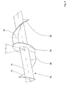
- cross auger 10 is composed of a circular cylindrical tubular body 12, a central, annular end plate 14 and two spiral windings 16, 18 together.
- the turns 16, 18 each extend helically from an outer end of the transverse screw conveyor 10 to the end plate 14 in the middle of the body 12.
- the turns 16, 18 respectively in an approximately radially to the body 12 extending edge 20 to the end plate 14 at and are attached there with a continuous weld.
- the outer diameter of the turns 16, 18 is constant over the length of the body 12 and is slightly less than the outer diameter of the end plate 14. In another embodiment, the diameter of the end plate 14 and turns 16, 18 coincide or the diameter of the end plate is slightly smaller than that of the windings 16, 18.
- brackets 22 are provided for attachment of the cross auger 10 on the frame of a header.
- the end plate 14 lies in a plane which encloses an angle ⁇ with the plane which extends orthogonal to the longitudinal axis of the body 12 through the center of the end plate 14.
- the angle ⁇ is relatively acute in the illustrated embodiment and is about 15 °. He could also be bigger or smaller. Because of this angle ⁇ , the outer periphery of the end plate 14 and its central opening surrounding the body 12 are not circular but elliptically shaped to keep the distance between the axis of rotation of the body 12 and the periphery of the end plate 14 constant, so that a given distance between the bottom of the header 24 ( FIG. 2 ) and the end plate 14 remains constant during its rotation. But it can also be any other shape of the circumference of the end plate 14 can be selected.
- the FIG. 2 shows a header 24 in the form of a corn picker with a cross auger 10 according to the invention.
- the header 24 has a frame 26, over the front of eight collection and picking 28 are distributed.
- the collection and picking 28 separate the crop stands (flasks) of the plants in the harvesting operation, the stems are shredded and stored in the field.
- the pistons are detected by the transverse screw conveyor 10, which is set in rotation about its longitudinal axis, and conveyed to the center of the header 24, at the rear side of which the inclined conveyor of a combine harvester is arranged.
- side parts 30 are provided which are pivotable by hydraulic cylinders 32 for transport upwards.
- the side parts 30 are equipped with transverse conveyor screw sections 34 which, in the illustrated working position, adjoin the transverse conveyor worm 12 and are connected in a torque-locking manner to the drive for the purpose of driving.
- the transverse screw conveyor 10 with the central end disk 14, on whose two sides the windings 16, 18 adjoin, causes not most of the crop to be discharged in the middle of the inclined conveyor. A considerable portion is delivered further to the left and right of the center with respect to the forward direction of the header 24, so that the combine harvester is charged approximately evenly.
- the end plate 14 also prevents plant winder at the ends of the turns 16, 18.
- By the angle ⁇ performs the end plate 14 during harvesting operation, in which the body 12 rotates about its longitudinal axis, a wobbling motion. It therefore successively sweeps over other parts of the bottom of the header 24 and the subsequent intake channel of the harvesting header 24-bearing harvester.
- An area in which no promotion of crop by the end plate 14 takes place, is - unlike in known, radially extending end plates - not available. The Erntegutieride is therefore significantly improved.
- FIG. 3 a second embodiment of a transverse screw conveyor 10 according to the invention is shown, which also in the header 24 from FIG. 2 is usable. Elements that correspond to the first embodiment are shown with the same reference numerals.
- the transverse screw conveyor 10 to FIG. 3 differs from the embodiment according to FIG. 1 essentially in that the turns 16, 18 end at a distance from the end plate 14 and there in areas 36, 38 pass, which extend axially and radially to the body 12. These areas 36, 38 reduce the movement of the crop to the center of the header 24 and assist in moving the harvester rearward into the harvester.
- the regions 36, 38 could also be windings, but having a greater pitch and / or a lower height above the body 12 than the outer windings 16, 18. In this embodiment, the outer diameters of the regions 36, 38, the turns 16, 18 and the end plate 14 approximately match.
Landscapes
- Life Sciences & Earth Sciences (AREA)
- Environmental Sciences (AREA)
- Outside Dividers And Delivering Mechanisms For Harvesters (AREA)
- Screw Conveyors (AREA)
- Earth Drilling (AREA)
- Harvester Elements (AREA)
- Threshing Machine Elements (AREA)
Claims (8)
- Hélice transporteuse transversale (10) pour un dispositif de récolte (24), avec un corps (12), des spires hélicoïdales (16, 18) disposées autour du corps (12), qui partent chaque fois d'un côté extérieur du corps (12) en direction de son milieu, et un disque d'extrémité (14) disposé en aval des spires (16, 18) et formant un anneau fermé, caractérisée en ce que le disque d'extrémité (14) s'étend dans un plan, qui forme un angle aigu (α) avec le plan s'étendant orthogonalement à l'axe longitudinal du corps (12).
- Hélice transporteuse transversale (10) selon la revendication 1, caractérisée en ce que le périmètre du disque d'extrémité (14) est elliptique, de telle manière que la distance entre le bord du disque d'extrémité (14) et l'axe de rotation du corps (12) soit constante sur le périmètre du disque d'extrémité (14).
- Hélice transporteuse transversale (10) selon l'une quelconque des revendications 1 ou 2, caractérisée en ce qu'elle ne comporte qu'un seul disque d'extrémité (14) disposé au milieu du corps (12).
- Hélice transporteuse transversale (10) selon la revendication 3, caractérisée en ce que le disque d'extrémité (14) se trouve au milieu devant un canal d'entrée d'une machine de récolte.
- Hélice transporteuse transversale (10) selon l'une quelconque des revendications 1 à 4, caractérisée en ce que les spires (16, 18) se raccordent au disque d'extrémité (14) selon une arête (20) s'étendant sensiblement radialement par rapport au corps (12).
- Hélice transporteuse transversale (10) selon l'une quelconque des revendications 1 à 5, caractérisée en ce que les spires (16, 18) se poursuivent chaque fois, à leurs extrémités voisines du milieu de l'hélice transporteuse transversale (10), par des zones (36, 38) s'étendant axialement par rapport au corps (12).
- Hélice transporteuse transversale (10) selon l'une quelconque des revendications 1 à 6, caractérisée en ce que le diamètre extérieur des spires (16, 18) est inférieur ou égal au diamètre extérieur du disque d'extrémité (14).
- Dispositif de récolte (24), en particulier cueilleuse de maïs, dispositif à maïs pour moissonneuse-batteuse, appareil de coupe ou dispositif de ramassage avec une hélice transporteuse transversale (10) selon l'une quelconque des revendications 1 à 7.
Applications Claiming Priority (1)
| Application Number | Priority Date | Filing Date | Title |
|---|---|---|---|
| DE102004033089A DE102004033089A1 (de) | 2004-07-08 | 2004-07-08 | Querförderschnecke für einen Erntevorsatz |
Publications (2)
| Publication Number | Publication Date |
|---|---|
| EP1614340A1 EP1614340A1 (fr) | 2006-01-11 |
| EP1614340B1 true EP1614340B1 (fr) | 2008-04-23 |
Family
ID=35229863
Family Applications (1)
| Application Number | Title | Priority Date | Filing Date |
|---|---|---|---|
| EP05105263A Expired - Lifetime EP1614340B1 (fr) | 2004-07-08 | 2005-06-15 | Hélice transporteuse transversale pour dispositif de récolte |
Country Status (5)
| Country | Link |
|---|---|
| US (1) | US7419048B2 (fr) |
| EP (1) | EP1614340B1 (fr) |
| AT (1) | ATE392805T1 (fr) |
| CA (1) | CA2511713C (fr) |
| DE (2) | DE102004033089A1 (fr) |
Cited By (1)
| Publication number | Priority date | Publication date | Assignee | Title |
|---|---|---|---|---|
| EP3991542A4 (fr) * | 2019-06-28 | 2023-09-06 | Kubota Corporation | Moissonneuse, système, programme, support d'enregistrement, et procédé |
Families Citing this family (9)
| Publication number | Priority date | Publication date | Assignee | Title |
|---|---|---|---|---|
| JP5035723B2 (ja) * | 2006-10-18 | 2012-09-26 | 株式会社リコー | トナー搬送装置、プロセスカートリッジ及び画像形成装置 |
| DE202009010983U1 (de) * | 2009-05-07 | 2011-06-15 | Doppstadt Familienholding GmbH, 42555 | Siebmaschine, insbesondere Sternsiebmaschine |
| CN102696338B (zh) * | 2012-06-05 | 2014-12-24 | 江苏大学 | 半喂入联合收割机配套的可调式秸秆扩散器 |
| PL2992751T3 (pl) * | 2014-09-05 | 2018-01-31 | Exel Ind | Układ zbierający do zebranych plonów i odpowiednia maszyna zbierająca |
| BE1022621B1 (nl) * | 2015-04-03 | 2016-06-17 | Cnh Industrial Belgium Nv | Opraapeenheid met een zwadconditioneringsrol voor een balenpers voor gebruik in de landbouw |
| US10021832B2 (en) * | 2015-08-20 | 2018-07-17 | Cnh Industrial America Llc | Row divider having a conveyor for an agricultural harvester |
| US10160605B1 (en) * | 2018-02-23 | 2018-12-25 | Laidig Systems, Inc. | Oscillating auger support |
| CN108377721B (zh) * | 2018-04-28 | 2024-06-11 | 山东省农业科学院 | 一种匍匐蔓生作物刈割抄底搂草装置 |
| DE102023110952A1 (de) * | 2023-04-27 | 2024-10-31 | Maschinenfabrik Bernard Krone GmbH & Co. KG | Fördervorrichtung für landwirtschaftliches Erntegut |
Family Cites Families (17)
| Publication number | Priority date | Publication date | Assignee | Title |
|---|---|---|---|---|
| US3244271A (en) * | 1964-10-26 | 1966-04-05 | Case Co J I | Auger for axially moving and laterally discharging material |
| US4180155A (en) * | 1976-12-01 | 1979-12-25 | Industrial Service & Manufacturing Co. | Multiple pitch self-cleaning belt pulley |
| US4641743A (en) * | 1986-01-21 | 1987-02-10 | Kemp Jr Dennis E | Junction device for auger conveyors |
| DE3738991C2 (de) * | 1987-11-17 | 1994-06-16 | Claas Ohg | Selbstfahrender Mähdrescher |
| DE3804598C2 (de) | 1988-02-13 | 1999-03-18 | Claas Saulgau Gmbh | Querförderschnecke für einen Mäh- oder Maiserntevorsatz |
| DE4109064C2 (de) | 1991-03-20 | 2000-04-06 | Claas Saulgau Gmbh | Maiserntegerät |
| IT1253105B (it) * | 1991-07-02 | 1995-07-10 | Seko Spa | Carro trincia-miscelatore-distributore perfezionato per foraggi e insilati di erba o paglia. |
| US5446435A (en) | 1991-09-20 | 1995-08-29 | Liaisons Electroniques-Mecaniques Lem S.A. | Current sensor comprising a magnetic circuit with an air gap |
| DE4206209A1 (de) * | 1992-02-28 | 1993-09-02 | Claas Saulgau Gmbh | Querfoerderschnecke fuer einen maeh- oder maiserntevorsatz |
| US5439182A (en) * | 1992-12-03 | 1995-08-08 | Sioux Automation Center, Inc. | Equipment/apparatus with one horizontal auger for cutting up and mixing of fibrous products used for the preparation of animal feed |
| IT1270579B (it) * | 1993-02-26 | 1997-05-06 | Seko Spa | Carro trincia-miscelatore-distributore per foraggi ed insilati di erba o paglia con coclee a profilo centrale perfezionato |
| BE1008654A3 (nl) * | 1994-08-24 | 1996-07-02 | Haegeman J H | Gecombineerde schroef voor waterbehandelingsapparaten. |
| US5732892A (en) * | 1996-08-15 | 1998-03-31 | J-Star Industries, Inc. | Self-loading auger |
| US5784869A (en) * | 1997-01-31 | 1998-07-28 | New Holland North America, Inc. | Corn head auger trough divider |
| DE19939168A1 (de) | 1999-08-20 | 2001-02-22 | Claas Saulgau Gmbh | Vorsatzgerät zum Ernten von stengeligem Erntegut |
| FR2813492B1 (fr) | 2000-09-06 | 2006-09-01 | Hydrotronic | Barre de coupe pour moissonneuse-batteuse ou engin similaire |
| DE10354977A1 (de) | 2003-11-25 | 2005-06-30 | Maschinenfabrik Kemper Gmbh & Co. Kg | Querförderschnecke für einen Erntevorsatz |
-
2004
- 2004-07-08 DE DE102004033089A patent/DE102004033089A1/de not_active Withdrawn
-
2005
- 2005-06-15 AT AT05105263T patent/ATE392805T1/de not_active IP Right Cessation
- 2005-06-15 DE DE502005003809T patent/DE502005003809D1/de not_active Expired - Lifetime
- 2005-06-15 EP EP05105263A patent/EP1614340B1/fr not_active Expired - Lifetime
- 2005-07-07 CA CA002511713A patent/CA2511713C/fr not_active Expired - Fee Related
- 2005-07-07 US US11/176,082 patent/US7419048B2/en active Active
Cited By (2)
| Publication number | Priority date | Publication date | Assignee | Title |
|---|---|---|---|---|
| EP3991542A4 (fr) * | 2019-06-28 | 2023-09-06 | Kubota Corporation | Moissonneuse, système, programme, support d'enregistrement, et procédé |
| US12083961B2 (en) | 2019-06-28 | 2024-09-10 | Kubota Corporation | Harvester, system, program, recording medium, and method |
Also Published As
| Publication number | Publication date |
|---|---|
| US20060005523A1 (en) | 2006-01-12 |
| US7419048B2 (en) | 2008-09-02 |
| DE102004033089A1 (de) | 2006-03-02 |
| DE502005003809D1 (de) | 2008-06-05 |
| ATE392805T1 (de) | 2008-05-15 |
| CA2511713C (fr) | 2009-05-12 |
| EP1614340A1 (fr) | 2006-01-11 |
| CA2511713A1 (fr) | 2006-01-08 |
Similar Documents
| Publication | Publication Date | Title |
|---|---|---|
| EP0803184B1 (fr) | Ramasseur | |
| EP1305998B1 (fr) | Dispositif d'introduction et de cueillage | |
| DE3525754A1 (de) | Erntekopf fuer eine maehmaschine | |
| EP2545762B1 (fr) | Appareil adaptable pour une moissonneuse-batteuse autotractée destinée à la récolte de produits agricoles en forme de tiges | |
| EP2614698B1 (fr) | Faucheuse | |
| DE29614549U1 (de) | Maschine zum reihenunabhängigen Mähen und Häckseln von Mais u.dgl. stengelartigem Erntegut | |
| DE2948272A1 (de) | Maehdrescher | |
| EP4371396A1 (fr) | Tête de récolte avec vis sans fin transversale à déplacement vertical | |
| EP0503468B1 (fr) | Dispositif de coupe pour moissonneuse-batteuse | |
| EP1537771A1 (fr) | Hélice transporteuse transversale pour un dispositif de récolte | |
| EP1614340A1 (fr) | Hélice transporteuse transversale pour dispositif de récolte | |
| EP1495664A1 (fr) | Machine pour faucher des plantes à tiges | |
| EP2923556B1 (fr) | Appareil frontal pour une moissonneuse-batteuse auto-tractée destinée à la récolte de maïs | |
| EP3238526B1 (fr) | Moissonneuse comprenant un ramasseur | |
| DE102012204416B4 (de) | Mehrtrommeldreschwerk | |
| DE102014110572B4 (de) | Verfahren und Steuerungseinrichtung zum Betreiben eines Feldhäckslers | |
| WO2023011683A1 (fr) | Tête de ramassage destinée à une récolteuse-hacheuse de préférence autotractée | |
| DE102021106374A1 (de) | Erntemaschine | |
| EP1129610B1 (fr) | Dispositif d'introduction et de cueillage pour une machine de récolte | |
| DE3209334A1 (de) | Anbaugeraet fuer erntemaschinen zum einzug von erntegut | |
| DE3804598C2 (de) | Querförderschnecke für einen Mäh- oder Maiserntevorsatz | |
| EP3593623B1 (fr) | Machine de récolte doté d'un dispositif de ramassage de récolte | |
| DE102016202324B4 (de) | Längenverstellbarer Schneckenfördererzusammenbau für einen Mähdrescher | |
| DE10232802A1 (de) | Erntemaschine | |
| EP1543714A2 (fr) | Dispositif de recolte de maize |
Legal Events
| Date | Code | Title | Description |
|---|---|---|---|
| PUAI | Public reference made under article 153(3) epc to a published international application that has entered the european phase |
Free format text: ORIGINAL CODE: 0009012 |
|
| AK | Designated contracting states |
Kind code of ref document: A1 Designated state(s): AT BE BG CH CY CZ DE DK EE ES FI FR GB GR HU IE IS IT LI LT LU MC NL PL PT RO SE SI SK TR |
|
| AX | Request for extension of the european patent |
Extension state: AL BA HR LV MK YU |
|
| 17P | Request for examination filed |
Effective date: 20060711 |
|
| AKX | Designation fees paid |
Designated state(s): AT BE BG CH CY CZ DE DK EE ES FI FR GB GR HU IE IS IT LI LT LU MC NL PL PT RO SE SI SK TR |
|
| 17Q | First examination report despatched |
Effective date: 20070312 |
|
| GRAP | Despatch of communication of intention to grant a patent |
Free format text: ORIGINAL CODE: EPIDOSNIGR1 |
|
| GRAS | Grant fee paid |
Free format text: ORIGINAL CODE: EPIDOSNIGR3 |
|
| GRAA | (expected) grant |
Free format text: ORIGINAL CODE: 0009210 |
|
| AK | Designated contracting states |
Kind code of ref document: B1 Designated state(s): AT BE BG CH CY CZ DE DK EE ES FI FR GB GR HU IE IS IT LI LT LU MC NL PL PT RO SE SI SK TR |
|
| REG | Reference to a national code |
Ref country code: GB Ref legal event code: FG4D Free format text: NOT ENGLISH |
|
| REG | Reference to a national code |
Ref country code: CH Ref legal event code: EP |
|
| REF | Corresponds to: |
Ref document number: 502005003809 Country of ref document: DE Date of ref document: 20080605 Kind code of ref document: P |
|
| REG | Reference to a national code |
Ref country code: IE Ref legal event code: FG4D Free format text: LANGUAGE OF EP DOCUMENT: GERMAN |
|
| PG25 | Lapsed in a contracting state [announced via postgrant information from national office to epo] |
Ref country code: SI Free format text: LAPSE BECAUSE OF FAILURE TO SUBMIT A TRANSLATION OF THE DESCRIPTION OR TO PAY THE FEE WITHIN THE PRESCRIBED TIME-LIMIT Effective date: 20080423 |
|
| NLV1 | Nl: lapsed or annulled due to failure to fulfill the requirements of art. 29p and 29m of the patents act | ||
| PG25 | Lapsed in a contracting state [announced via postgrant information from national office to epo] |
Ref country code: NL Free format text: LAPSE BECAUSE OF FAILURE TO SUBMIT A TRANSLATION OF THE DESCRIPTION OR TO PAY THE FEE WITHIN THE PRESCRIBED TIME-LIMIT Effective date: 20080423 Ref country code: PT Free format text: LAPSE BECAUSE OF FAILURE TO SUBMIT A TRANSLATION OF THE DESCRIPTION OR TO PAY THE FEE WITHIN THE PRESCRIBED TIME-LIMIT Effective date: 20080923 Ref country code: BG Free format text: LAPSE BECAUSE OF FAILURE TO SUBMIT A TRANSLATION OF THE DESCRIPTION OR TO PAY THE FEE WITHIN THE PRESCRIBED TIME-LIMIT Effective date: 20080723 Ref country code: FI Free format text: LAPSE BECAUSE OF FAILURE TO SUBMIT A TRANSLATION OF THE DESCRIPTION OR TO PAY THE FEE WITHIN THE PRESCRIBED TIME-LIMIT Effective date: 20080423 Ref country code: ES Free format text: LAPSE BECAUSE OF FAILURE TO SUBMIT A TRANSLATION OF THE DESCRIPTION OR TO PAY THE FEE WITHIN THE PRESCRIBED TIME-LIMIT Effective date: 20080803 |
|
| PG25 | Lapsed in a contracting state [announced via postgrant information from national office to epo] |
Ref country code: PL Free format text: LAPSE BECAUSE OF FAILURE TO SUBMIT A TRANSLATION OF THE DESCRIPTION OR TO PAY THE FEE WITHIN THE PRESCRIBED TIME-LIMIT Effective date: 20080423 |
|
| REG | Reference to a national code |
Ref country code: IE Ref legal event code: FD4D |
|
| PG25 | Lapsed in a contracting state [announced via postgrant information from national office to epo] |
Ref country code: IS Free format text: LAPSE BECAUSE OF FAILURE TO SUBMIT A TRANSLATION OF THE DESCRIPTION OR TO PAY THE FEE WITHIN THE PRESCRIBED TIME-LIMIT Effective date: 20080823 |
|
| PG25 | Lapsed in a contracting state [announced via postgrant information from national office to epo] |
Ref country code: DK Free format text: LAPSE BECAUSE OF FAILURE TO SUBMIT A TRANSLATION OF THE DESCRIPTION OR TO PAY THE FEE WITHIN THE PRESCRIBED TIME-LIMIT Effective date: 20080423 Ref country code: IE Free format text: LAPSE BECAUSE OF FAILURE TO SUBMIT A TRANSLATION OF THE DESCRIPTION OR TO PAY THE FEE WITHIN THE PRESCRIBED TIME-LIMIT Effective date: 20080423 Ref country code: LT Free format text: LAPSE BECAUSE OF FAILURE TO SUBMIT A TRANSLATION OF THE DESCRIPTION OR TO PAY THE FEE WITHIN THE PRESCRIBED TIME-LIMIT Effective date: 20080423 Ref country code: MC Free format text: LAPSE BECAUSE OF NON-PAYMENT OF DUE FEES Effective date: 20080630 Ref country code: CZ Free format text: LAPSE BECAUSE OF FAILURE TO SUBMIT A TRANSLATION OF THE DESCRIPTION OR TO PAY THE FEE WITHIN THE PRESCRIBED TIME-LIMIT Effective date: 20080423 Ref country code: SE Free format text: LAPSE BECAUSE OF FAILURE TO SUBMIT A TRANSLATION OF THE DESCRIPTION OR TO PAY THE FEE WITHIN THE PRESCRIBED TIME-LIMIT Effective date: 20080723 |
|
| EN | Fr: translation not filed | ||
| PG25 | Lapsed in a contracting state [announced via postgrant information from national office to epo] |
Ref country code: RO Free format text: LAPSE BECAUSE OF FAILURE TO SUBMIT A TRANSLATION OF THE DESCRIPTION OR TO PAY THE FEE WITHIN THE PRESCRIBED TIME-LIMIT Effective date: 20080423 Ref country code: SK Free format text: LAPSE BECAUSE OF FAILURE TO SUBMIT A TRANSLATION OF THE DESCRIPTION OR TO PAY THE FEE WITHIN THE PRESCRIBED TIME-LIMIT Effective date: 20080423 |
|
| PLBE | No opposition filed within time limit |
Free format text: ORIGINAL CODE: 0009261 |
|
| STAA | Information on the status of an ep patent application or granted ep patent |
Free format text: STATUS: NO OPPOSITION FILED WITHIN TIME LIMIT |
|
| 26N | No opposition filed |
Effective date: 20090126 |
|
| PG25 | Lapsed in a contracting state [announced via postgrant information from national office to epo] |
Ref country code: EE Free format text: LAPSE BECAUSE OF FAILURE TO SUBMIT A TRANSLATION OF THE DESCRIPTION OR TO PAY THE FEE WITHIN THE PRESCRIBED TIME-LIMIT Effective date: 20080423 Ref country code: FR Free format text: LAPSE BECAUSE OF FAILURE TO SUBMIT A TRANSLATION OF THE DESCRIPTION OR TO PAY THE FEE WITHIN THE PRESCRIBED TIME-LIMIT Effective date: 20090227 |
|
| PG25 | Lapsed in a contracting state [announced via postgrant information from national office to epo] |
Ref country code: AT Free format text: LAPSE BECAUSE OF NON-PAYMENT OF DUE FEES Effective date: 20080615 |
|
| PGFP | Annual fee paid to national office [announced via postgrant information from national office to epo] |
Ref country code: IT Payment date: 20090625 Year of fee payment: 5 |
|
| REG | Reference to a national code |
Ref country code: CH Ref legal event code: PL |
|
| GBPC | Gb: european patent ceased through non-payment of renewal fee |
Effective date: 20090615 |
|
| PGFP | Annual fee paid to national office [announced via postgrant information from national office to epo] |
Ref country code: BE Payment date: 20090715 Year of fee payment: 5 |
|
| PG25 | Lapsed in a contracting state [announced via postgrant information from national office to epo] |
Ref country code: LI Free format text: LAPSE BECAUSE OF NON-PAYMENT OF DUE FEES Effective date: 20090630 Ref country code: CH Free format text: LAPSE BECAUSE OF NON-PAYMENT OF DUE FEES Effective date: 20090630 |
|
| PG25 | Lapsed in a contracting state [announced via postgrant information from national office to epo] |
Ref country code: GB Free format text: LAPSE BECAUSE OF NON-PAYMENT OF DUE FEES Effective date: 20090615 |
|
| PG25 | Lapsed in a contracting state [announced via postgrant information from national office to epo] |
Ref country code: HU Free format text: LAPSE BECAUSE OF FAILURE TO SUBMIT A TRANSLATION OF THE DESCRIPTION OR TO PAY THE FEE WITHIN THE PRESCRIBED TIME-LIMIT Effective date: 20081024 Ref country code: CY Free format text: LAPSE BECAUSE OF FAILURE TO SUBMIT A TRANSLATION OF THE DESCRIPTION OR TO PAY THE FEE WITHIN THE PRESCRIBED TIME-LIMIT Effective date: 20080423 Ref country code: LU Free format text: LAPSE BECAUSE OF NON-PAYMENT OF DUE FEES Effective date: 20080615 |
|
| PG25 | Lapsed in a contracting state [announced via postgrant information from national office to epo] |
Ref country code: TR Free format text: LAPSE BECAUSE OF FAILURE TO SUBMIT A TRANSLATION OF THE DESCRIPTION OR TO PAY THE FEE WITHIN THE PRESCRIBED TIME-LIMIT Effective date: 20080423 |
|
| PG25 | Lapsed in a contracting state [announced via postgrant information from national office to epo] |
Ref country code: GR Free format text: LAPSE BECAUSE OF FAILURE TO SUBMIT A TRANSLATION OF THE DESCRIPTION OR TO PAY THE FEE WITHIN THE PRESCRIBED TIME-LIMIT Effective date: 20080724 |
|
| BERE | Be: lapsed |
Owner name: MASCHINENFABRIK KEMPER G.M.B.H. & CO. KG Effective date: 20100630 |
|
| PG25 | Lapsed in a contracting state [announced via postgrant information from national office to epo] |
Ref country code: IT Free format text: LAPSE BECAUSE OF NON-PAYMENT OF DUE FEES Effective date: 20100615 |
|
| PG25 | Lapsed in a contracting state [announced via postgrant information from national office to epo] |
Ref country code: BE Free format text: LAPSE BECAUSE OF NON-PAYMENT OF DUE FEES Effective date: 20100630 |
|
| PGFP | Annual fee paid to national office [announced via postgrant information from national office to epo] |
Ref country code: DE Payment date: 20140521 Year of fee payment: 10 |
|
| REG | Reference to a national code |
Ref country code: DE Ref legal event code: R119 Ref document number: 502005003809 Country of ref document: DE |
|
| PG25 | Lapsed in a contracting state [announced via postgrant information from national office to epo] |
Ref country code: DE Free format text: LAPSE BECAUSE OF NON-PAYMENT OF DUE FEES Effective date: 20160101 |