EP1614466A2 - Dispositif et procédé pour la prévention de bulles d'air dans une chambre d'hybridation - Google Patents
Dispositif et procédé pour la prévention de bulles d'air dans une chambre d'hybridation Download PDFInfo
- Publication number
- EP1614466A2 EP1614466A2 EP05105498A EP05105498A EP1614466A2 EP 1614466 A2 EP1614466 A2 EP 1614466A2 EP 05105498 A EP05105498 A EP 05105498A EP 05105498 A EP05105498 A EP 05105498A EP 1614466 A2 EP1614466 A2 EP 1614466A2
- Authority
- EP
- European Patent Office
- Prior art keywords
- pressure
- hybridization
- chamber
- agitation
- hybridisierkammern
- Prior art date
- Legal status (The legal status is an assumption and is not a legal conclusion. Google has not performed a legal analysis and makes no representation as to the accuracy of the status listed.)
- Ceased
Links
- 238000009396 hybridization Methods 0.000 title claims description 147
- 238000000034 method Methods 0.000 title claims description 32
- 239000003570 air Substances 0.000 claims abstract description 34
- 239000012080 ambient air Substances 0.000 claims abstract description 15
- 238000013019 agitation Methods 0.000 claims description 67
- 239000007788 liquid Substances 0.000 claims description 46
- 239000007789 gas Substances 0.000 claims description 38
- 238000009826 distribution Methods 0.000 claims description 28
- 239000012528 membrane Substances 0.000 claims description 21
- 239000002699 waste material Substances 0.000 claims description 21
- 239000011261 inert gas Substances 0.000 claims description 14
- 108090000623 proteins and genes Proteins 0.000 claims description 10
- 108020004707 nucleic acids Proteins 0.000 claims description 8
- 102000039446 nucleic acids Human genes 0.000 claims description 8
- 150000007523 nucleic acids Chemical class 0.000 claims description 8
- 102000004169 proteins and genes Human genes 0.000 claims description 8
- 230000008569 process Effects 0.000 claims description 7
- 239000012530 fluid Substances 0.000 abstract description 8
- 230000015572 biosynthetic process Effects 0.000 abstract description 5
- 239000000969 carrier Substances 0.000 abstract description 3
- 239000000523 sample Substances 0.000 description 24
- 108020004414 DNA Proteins 0.000 description 15
- 239000000872 buffer Substances 0.000 description 11
- 108091032973 (ribonucleotides)n+m Proteins 0.000 description 10
- 238000005406 washing Methods 0.000 description 9
- 239000013642 negative control Substances 0.000 description 7
- 238000007789 sealing Methods 0.000 description 6
- XLYOFNOQVPJJNP-UHFFFAOYSA-N water Substances O XLYOFNOQVPJJNP-UHFFFAOYSA-N 0.000 description 6
- IJGRMHOSHXDMSA-UHFFFAOYSA-N Atomic nitrogen Chemical compound N#N IJGRMHOSHXDMSA-UHFFFAOYSA-N 0.000 description 5
- 238000003491 array Methods 0.000 description 5
- 238000010586 diagram Methods 0.000 description 5
- 238000012360 testing method Methods 0.000 description 5
- 239000011534 wash buffer Substances 0.000 description 5
- 238000001035 drying Methods 0.000 description 4
- 239000002904 solvent Substances 0.000 description 4
- 238000000018 DNA microarray Methods 0.000 description 3
- 108091034117 Oligonucleotide Proteins 0.000 description 3
- 241000282487 Vulpes Species 0.000 description 3
- 239000003153 chemical reaction reagent Substances 0.000 description 3
- 150000001875 compounds Chemical class 0.000 description 3
- 239000012153 distilled water Substances 0.000 description 3
- 230000000694 effects Effects 0.000 description 3
- 238000011049 filling Methods 0.000 description 3
- 230000014509 gene expression Effects 0.000 description 3
- 230000007246 mechanism Effects 0.000 description 3
- 229920006395 saturated elastomer Polymers 0.000 description 3
- 230000002269 spontaneous effect Effects 0.000 description 3
- 241001136792 Alle Species 0.000 description 2
- 206010013786 Dry skin Diseases 0.000 description 2
- JLCPHMBAVCMARE-UHFFFAOYSA-N [3-[[3-[[3-[[3-[[3-[[3-[[3-[[3-[[3-[[3-[[3-[[5-(2-amino-6-oxo-1H-purin-9-yl)-3-[[3-[[3-[[3-[[3-[[3-[[5-(2-amino-6-oxo-1H-purin-9-yl)-3-[[5-(2-amino-6-oxo-1H-purin-9-yl)-3-hydroxyoxolan-2-yl]methoxy-hydroxyphosphoryl]oxyoxolan-2-yl]methoxy-hydroxyphosphoryl]oxy-5-(5-methyl-2,4-dioxopyrimidin-1-yl)oxolan-2-yl]methoxy-hydroxyphosphoryl]oxy-5-(6-aminopurin-9-yl)oxolan-2-yl]methoxy-hydroxyphosphoryl]oxy-5-(6-aminopurin-9-yl)oxolan-2-yl]methoxy-hydroxyphosphoryl]oxy-5-(6-aminopurin-9-yl)oxolan-2-yl]methoxy-hydroxyphosphoryl]oxy-5-(6-aminopurin-9-yl)oxolan-2-yl]methoxy-hydroxyphosphoryl]oxyoxolan-2-yl]methoxy-hydroxyphosphoryl]oxy-5-(5-methyl-2,4-dioxopyrimidin-1-yl)oxolan-2-yl]methoxy-hydroxyphosphoryl]oxy-5-(4-amino-2-oxopyrimidin-1-yl)oxolan-2-yl]methoxy-hydroxyphosphoryl]oxy-5-(5-methyl-2,4-dioxopyrimidin-1-yl)oxolan-2-yl]methoxy-hydroxyphosphoryl]oxy-5-(5-methyl-2,4-dioxopyrimidin-1-yl)oxolan-2-yl]methoxy-hydroxyphosphoryl]oxy-5-(6-aminopurin-9-yl)oxolan-2-yl]methoxy-hydroxyphosphoryl]oxy-5-(6-aminopurin-9-yl)oxolan-2-yl]methoxy-hydroxyphosphoryl]oxy-5-(4-amino-2-oxopyrimidin-1-yl)oxolan-2-yl]methoxy-hydroxyphosphoryl]oxy-5-(4-amino-2-oxopyrimidin-1-yl)oxolan-2-yl]methoxy-hydroxyphosphoryl]oxy-5-(4-amino-2-oxopyrimidin-1-yl)oxolan-2-yl]methoxy-hydroxyphosphoryl]oxy-5-(6-aminopurin-9-yl)oxolan-2-yl]methoxy-hydroxyphosphoryl]oxy-5-(4-amino-2-oxopyrimidin-1-yl)oxolan-2-yl]methyl [5-(6-aminopurin-9-yl)-2-(hydroxymethyl)oxolan-3-yl] hydrogen phosphate Polymers Cc1cn(C2CC(OP(O)(=O)OCC3OC(CC3OP(O)(=O)OCC3OC(CC3O)n3cnc4c3nc(N)[nH]c4=O)n3cnc4c3nc(N)[nH]c4=O)C(COP(O)(=O)OC3CC(OC3COP(O)(=O)OC3CC(OC3COP(O)(=O)OC3CC(OC3COP(O)(=O)OC3CC(OC3COP(O)(=O)OC3CC(OC3COP(O)(=O)OC3CC(OC3COP(O)(=O)OC3CC(OC3COP(O)(=O)OC3CC(OC3COP(O)(=O)OC3CC(OC3COP(O)(=O)OC3CC(OC3COP(O)(=O)OC3CC(OC3COP(O)(=O)OC3CC(OC3COP(O)(=O)OC3CC(OC3COP(O)(=O)OC3CC(OC3COP(O)(=O)OC3CC(OC3COP(O)(=O)OC3CC(OC3COP(O)(=O)OC3CC(OC3CO)n3cnc4c(N)ncnc34)n3ccc(N)nc3=O)n3cnc4c(N)ncnc34)n3ccc(N)nc3=O)n3ccc(N)nc3=O)n3ccc(N)nc3=O)n3cnc4c(N)ncnc34)n3cnc4c(N)ncnc34)n3cc(C)c(=O)[nH]c3=O)n3cc(C)c(=O)[nH]c3=O)n3ccc(N)nc3=O)n3cc(C)c(=O)[nH]c3=O)n3cnc4c3nc(N)[nH]c4=O)n3cnc4c(N)ncnc34)n3cnc4c(N)ncnc34)n3cnc4c(N)ncnc34)n3cnc4c(N)ncnc34)O2)c(=O)[nH]c1=O JLCPHMBAVCMARE-UHFFFAOYSA-N 0.000 description 2
- 239000012298 atmosphere Substances 0.000 description 2
- TZCXTZWJZNENPQ-UHFFFAOYSA-L barium sulfate Chemical compound [Ba+2].[O-]S([O-])(=O)=O TZCXTZWJZNENPQ-UHFFFAOYSA-L 0.000 description 2
- 238000007664 blowing Methods 0.000 description 2
- 238000006243 chemical reaction Methods 0.000 description 2
- 239000003795 chemical substances by application Substances 0.000 description 2
- 239000002299 complementary DNA Substances 0.000 description 2
- 238000007599 discharging Methods 0.000 description 2
- 239000011521 glass Substances 0.000 description 2
- 238000002347 injection Methods 0.000 description 2
- 239000007924 injection Substances 0.000 description 2
- 230000003993 interaction Effects 0.000 description 2
- 238000005259 measurement Methods 0.000 description 2
- 238000002493 microarray Methods 0.000 description 2
- 229910052757 nitrogen Inorganic materials 0.000 description 2
- 102000004196 processed proteins & peptides Human genes 0.000 description 2
- 108090000765 processed proteins & peptides Proteins 0.000 description 2
- 238000012545 processing Methods 0.000 description 2
- 230000033764 rhythmic process Effects 0.000 description 2
- 239000012488 sample solution Substances 0.000 description 2
- 239000000126 substance Substances 0.000 description 2
- 239000000758 substrate Substances 0.000 description 2
- 239000000725 suspension Substances 0.000 description 2
- 102000040650 (ribonucleotides)n+m Human genes 0.000 description 1
- 102000053602 DNA Human genes 0.000 description 1
- 239000003298 DNA probe Substances 0.000 description 1
- LFQSCWFLJHTTHZ-UHFFFAOYSA-N Ethanol Chemical compound CCO LFQSCWFLJHTTHZ-UHFFFAOYSA-N 0.000 description 1
- 229920002449 FKM Polymers 0.000 description 1
- 108091028043 Nucleic acid sequence Proteins 0.000 description 1
- 108091005461 Nucleic proteins Proteins 0.000 description 1
- 239000004698 Polyethylene Substances 0.000 description 1
- 239000013614 RNA sample Substances 0.000 description 1
- 150000001413 amino acids Chemical class 0.000 description 1
- 238000004458 analytical method Methods 0.000 description 1
- 230000008901 benefit Effects 0.000 description 1
- 239000012620 biological material Substances 0.000 description 1
- 238000011095 buffer preparation Methods 0.000 description 1
- 238000004140 cleaning Methods 0.000 description 1
- 238000004891 communication Methods 0.000 description 1
- 238000010276 construction Methods 0.000 description 1
- 230000007423 decrease Effects 0.000 description 1
- 230000003247 decreasing effect Effects 0.000 description 1
- 230000001419 dependent effect Effects 0.000 description 1
- 238000009792 diffusion process Methods 0.000 description 1
- 229910001873 dinitrogen Inorganic materials 0.000 description 1
- 229920001971 elastomer Polymers 0.000 description 1
- 239000000806 elastomer Substances 0.000 description 1
- 238000005516 engineering process Methods 0.000 description 1
- 238000002474 experimental method Methods 0.000 description 1
- 230000005661 hydrophobic surface Effects 0.000 description 1
- 238000002032 lab-on-a-chip Methods 0.000 description 1
- 238000011068 loading method Methods 0.000 description 1
- 230000014759 maintenance of location Effects 0.000 description 1
- 238000000386 microscopy Methods 0.000 description 1
- 238000002156 mixing Methods 0.000 description 1
- 239000002773 nucleotide Substances 0.000 description 1
- 125000003729 nucleotide group Chemical group 0.000 description 1
- 239000004033 plastic Substances 0.000 description 1
- 229920003023 plastic Polymers 0.000 description 1
- 229920001084 poly(chloroprene) Polymers 0.000 description 1
- -1 polyethylene Polymers 0.000 description 1
- 229920000573 polyethylene Polymers 0.000 description 1
- 229920001184 polypeptide Polymers 0.000 description 1
- 229920001296 polysiloxane Polymers 0.000 description 1
- 239000004810 polytetrafluoroethylene Substances 0.000 description 1
- 229920001343 polytetrafluoroethylene Polymers 0.000 description 1
- 238000002360 preparation method Methods 0.000 description 1
- 230000009467 reduction Effects 0.000 description 1
- 230000001105 regulatory effect Effects 0.000 description 1
- 230000002940 repellent Effects 0.000 description 1
- 239000005871 repellent Substances 0.000 description 1
- 238000011160 research Methods 0.000 description 1
- 238000005070 sampling Methods 0.000 description 1
- 239000003566 sealing material Substances 0.000 description 1
- 230000035945 sensitivity Effects 0.000 description 1
- 238000000926 separation method Methods 0.000 description 1
- 239000007787 solid Substances 0.000 description 1
- 239000000243 solution Substances 0.000 description 1
- 238000003860 storage Methods 0.000 description 1
- 230000001360 synchronised effect Effects 0.000 description 1
- 238000012546 transfer Methods 0.000 description 1
- 230000007704 transition Effects 0.000 description 1
- 238000009827 uniform distribution Methods 0.000 description 1
Images

Classifications
-
- B—PERFORMING OPERATIONS; TRANSPORTING
- B01—PHYSICAL OR CHEMICAL PROCESSES OR APPARATUS IN GENERAL
- B01L—CHEMICAL OR PHYSICAL LABORATORY APPARATUS FOR GENERAL USE
- B01L3/00—Containers or dishes for laboratory use, e.g. laboratory glassware; Droppers
- B01L3/50—Containers for the purpose of retaining a material to be analysed, e.g. test tubes
- B01L3/502—Containers for the purpose of retaining a material to be analysed, e.g. test tubes with fluid transport, e.g. in multi-compartment structures
- B01L3/5027—Containers for the purpose of retaining a material to be analysed, e.g. test tubes with fluid transport, e.g. in multi-compartment structures by integrated microfluidic structures, i.e. dimensions of channels and chambers are such that surface tension forces are important, e.g. lab-on-a-chip
- B01L3/50273—Containers for the purpose of retaining a material to be analysed, e.g. test tubes with fluid transport, e.g. in multi-compartment structures by integrated microfluidic structures, i.e. dimensions of channels and chambers are such that surface tension forces are important, e.g. lab-on-a-chip characterised by the means or forces applied to move the fluids
-
- B—PERFORMING OPERATIONS; TRANSPORTING
- B01—PHYSICAL OR CHEMICAL PROCESSES OR APPARATUS IN GENERAL
- B01F—MIXING, e.g. DISSOLVING, EMULSIFYING OR DISPERSING
- B01F31/00—Mixers with shaking, oscillating, or vibrating mechanisms
- B01F31/65—Mixers with shaking, oscillating, or vibrating mechanisms the materials to be mixed being directly submitted to a pulsating movement, e.g. by means of an oscillating piston or air column
-
- B—PERFORMING OPERATIONS; TRANSPORTING
- B01—PHYSICAL OR CHEMICAL PROCESSES OR APPARATUS IN GENERAL
- B01F—MIXING, e.g. DISSOLVING, EMULSIFYING OR DISPERSING
- B01F33/00—Other mixers; Mixing plants; Combinations of mixers
- B01F33/30—Micromixers
-
- B—PERFORMING OPERATIONS; TRANSPORTING
- B01—PHYSICAL OR CHEMICAL PROCESSES OR APPARATUS IN GENERAL
- B01L—CHEMICAL OR PHYSICAL LABORATORY APPARATUS FOR GENERAL USE
- B01L2200/00—Solutions for specific problems relating to chemical or physical laboratory apparatus
- B01L2200/14—Process control and prevention of errors
-
- B—PERFORMING OPERATIONS; TRANSPORTING
- B01—PHYSICAL OR CHEMICAL PROCESSES OR APPARATUS IN GENERAL
- B01L—CHEMICAL OR PHYSICAL LABORATORY APPARATUS FOR GENERAL USE
- B01L2300/00—Additional constructional details
- B01L2300/06—Auxiliary integrated devices, integrated components
- B01L2300/0627—Sensor or part of a sensor is integrated
- B01L2300/0636—Integrated biosensor, microarrays
-
- B—PERFORMING OPERATIONS; TRANSPORTING
- B01—PHYSICAL OR CHEMICAL PROCESSES OR APPARATUS IN GENERAL
- B01L—CHEMICAL OR PHYSICAL LABORATORY APPARATUS FOR GENERAL USE
- B01L2300/00—Additional constructional details
- B01L2300/08—Geometry, shape and general structure
- B01L2300/0809—Geometry, shape and general structure rectangular shaped
- B01L2300/0822—Slides
-
- B—PERFORMING OPERATIONS; TRANSPORTING
- B01—PHYSICAL OR CHEMICAL PROCESSES OR APPARATUS IN GENERAL
- B01L—CHEMICAL OR PHYSICAL LABORATORY APPARATUS FOR GENERAL USE
- B01L2300/00—Additional constructional details
- B01L2300/08—Geometry, shape and general structure
- B01L2300/0861—Configuration of multiple channels and/or chambers in a single devices
- B01L2300/0877—Flow chambers
-
- B—PERFORMING OPERATIONS; TRANSPORTING
- B01—PHYSICAL OR CHEMICAL PROCESSES OR APPARATUS IN GENERAL
- B01L—CHEMICAL OR PHYSICAL LABORATORY APPARATUS FOR GENERAL USE
- B01L2300/00—Additional constructional details
- B01L2300/14—Means for pressure control
-
- B—PERFORMING OPERATIONS; TRANSPORTING
- B01—PHYSICAL OR CHEMICAL PROCESSES OR APPARATUS IN GENERAL
- B01L—CHEMICAL OR PHYSICAL LABORATORY APPARATUS FOR GENERAL USE
- B01L2400/00—Moving or stopping fluids
- B01L2400/04—Moving fluids with specific forces or mechanical means
- B01L2400/0475—Moving fluids with specific forces or mechanical means specific mechanical means and fluid pressure
- B01L2400/0487—Moving fluids with specific forces or mechanical means specific mechanical means and fluid pressure fluid pressure, pneumatics
-
- B—PERFORMING OPERATIONS; TRANSPORTING
- B01—PHYSICAL OR CHEMICAL PROCESSES OR APPARATUS IN GENERAL
- B01L—CHEMICAL OR PHYSICAL LABORATORY APPARATUS FOR GENERAL USE
- B01L7/00—Heating or cooling apparatus; Heat insulating devices
- B01L7/52—Heating or cooling apparatus; Heat insulating devices with provision for submitting samples to a predetermined sequence of different temperatures, e.g. for treating nucleic acid samples
Definitions
- the invention relates to a system with hybridization chambers for hybridizing nucleic acid samples, proteins or tissue sections immobilized on microscope slides.
- each hybridization chamber is defined as a substantially gap-shaped, with a liquid substantially fillable space between one of these slides and a lid.
- Each lid is arranged opposite the slide in such a way that the hybridization chamber is sealed off from the ambient air.
- Such a system comprises an agitation device with which liquids in the hybridization chambers can be moved relative to the samples immobilized on the object carriers.
- the invention also relates, according to the preamble of independent claim 14, to a corresponding method for preventing air bubbles in the hybridization chambers of a system for hybridizing nucleic acid samples, proteins or tissue sections immobilized on slides.
- a corresponding method for preventing air bubbles in the hybridization chambers of a system for hybridizing nucleic acid samples, proteins or tissue sections immobilized on slides According to this method, all substantially gap-shaped, between one of these slides and a lid arranged hybridization chambers are filled with a liquid substantially.
- the lid is arranged in such a way relative to the slide that the hybridization chamber is sealed off from the ambient air.
- DNA samples deoxyribose nucleic acid
- microarrays of such samples provides research with an important technique for the simultaneous analysis of thousands of genes.
- This technique involves the immobilization of DNA probes from many genes on a solid substrate surface, e.g. on a glass slide for a light microscope.
- the DNA samples are preferably stored in an array of sample spots or "spots", i. arranged in a two-dimensional grid on the substrate and one can later - starting from a certain position within such an array on the origin of the corresponding DNA sample infer.
- pattern suspensions are also used which contain DNA, cDNA and / or proteins or polypeptides.
- RNA patterns may be labeled with a so-called "tag” or "label", i. be provided with a molecule which is e.g. emits a fluorescent light having a specific wavelength.
- Immobilized samples may also include amino acid-containing (e.g., proteins, peptides) or nucleic acid-containing (e.g., cDNA, RNA) probes. Samples added to the immobilized samples may comprise any molecules or chemical compounds that hybridize or otherwise associate with the immobilized samples.
- the RNA patterns hybridize or bind to the immobilized DNA samples and together form hybrid DNA-RNA strands.
- differences in the hybridization among the DNA samples can be determined by measuring the intensity and wavelength dependency of the fluorescence of each individual microarray element to determine whether the level of gene expression in the DNA sample varies the examined DNA samples.
- DNA microarrays have become established as successful tools, and devices for performing DNA hybridization have been continually improved (see, for example, US 6,238,910 or EP 1 260 265 A1 of the Applicant of the current patent application).
- These documents disclose a device for providing a hybridization space for the hybridization of nucleic acid samples on a slide.
- These devices are designed to be movable relative to the slide and comprise an annular seal or sealing surface for closing the gap-shaped hybridization space with respect to the ambient air, wherein a surface of this slide is acted upon by the seal or sealing surface.
- these devices include lines for feeding or discharging media into the hybridization space or out of the hybridization space as well as a sample feed.
- An improved temperature control and movement of the liquid with e.g. RNA patterns against DNA samples immobilized on the slide are also disclosed.
- the object of the present invention relates to the provision of an alternative system or an alternative method, with which the formation of air bubbles in a hybridization chamber can be prevented in a simple manner.
- a system described above comprises means for preventing air bubbles in the Hybridisierhuntn, which is designed as a pressure means for establishing a chamber pressure in the Hybridisierhuntn, wherein This chamber pressure thereby independent of agitation pressure differences over that in the ambient air prevailing, normal atmospheric pressure is that the system comprises at least one spring element, which communicates with the liquid volume used for the hybridization and resiliently counteracts the agitation pressure differences exerted by the agitator on the pressure chamber agitation pressure differences.
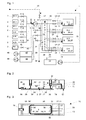
- FIG. 1 shows a diagram of a system 1 suitable for carrying out the method according to the invention.
- vessels 2 for the storage of liquid hybridization media, such as washing liquids (W 3, W 2, W 1), prehybridization buffer ( VP), alcohol cleaning fluid (AR), distilled water (AD), and a container 3 with inert gas (N2).
- Each of these vessels 2 is preceded by an individual valve 4, via which these media can be supplied to the hybridization chambers 5 (S 1, S 2, S 3, S 4) (shown on the right-hand side).
- the valve lines 4 comprehensive media lines 6 open into a manifold 7, which in turn opens into a feed pump 8, which is preceded by a vent valve 9.
- This feed pump 8 draws liquid media from the vessels 2 via the collecting line 7 and pumps them via the distribution line 10 into the inlet lines 11, which open into the hybridization chambers 5 via an inlet valve 12.
- the hybridizing media leave the Hybridisierhuntn 5 via an outlet 13, which each comprise an outlet valve 14 and open into a manifold 15.
- This manifold 15 in turn opens into a waste line 16, which is closable by means of a waste valve 17.
- the distribution line 10 and the manifold 15 can communicate with each other via a connecting line 18 and a connecting valve 19. From this connecting line 18 branches off a discharge line 20 with a relief valve 21 and flows into a sump 22 with a loading or vent 23.
- the sump 22 downstream of a feed pump 24 which is connected via a transition line 25 to the waste line 16.
- the system 1 is equipped with an agitation mechanism or with an agitation device 32, as is known from the European patent application EP 1 260 265 A1 of the applicant of the current patent application.
- the content of this patent application EP 1 260 265 A1 is hereby expressly incorporated by reference, so that this content is part of the present patent application.
- FIG. 2 shows a vertical longitudinal section through a hybridization chamber 5 corresponding to FIG. 1 of EP 1 260 265 A1.
- the cover 26 of this arrangement is movable relative to the slide 27 (in this case pivotable about an axis, so that the hybridization space 5 is replaced by a simple
- An annular sealing surface 28 serves to close off the hybridization space 5 by acting on a surface 29 of this slide 27.
- This sealing surface 28 may be a stepped surface of the lid 26 lying flat on the surface 29 of the slide 27; For example, a lip seal may also be used, but an O-ring seal is preferred as the sealing surface 28.
- the arrangement comprises lines 11, 13 for feeding or discharging media into the hybridization space 5 or out of the hybridization space 5.
- Such media may include reagents for carrying out the hybridization reaction, such as washings or inert gases (such as nitrogen) for drying the hybridization products on the slides 27 and for blowing out the Hybridisierhuntn 5 and the media lines 11,13 be.
- These supply and discharge lines 11, 13 for hybridization media preferably open into a respective agitation space 30, 30 '.
- the assembly also includes a sealable pattern feeder 31 through which RNA-containing liquids or other sample liquids can be pipetted by hand.
- the pattern feeder 31 is preferably closed with a plastic plug (not shown).
- an automatic or robotized pattern feeder may be provided, as disclosed in different embodiments in EP 1 260 265 A1.
- the arrangement comprises a media-separating agitation device 32 for moving liquids against samples of nucleic acids, proteins or tissue sections immobilized on the surface 29 of the slides 27.
- the agitation device 32 of the arrangement comprises a membrane 33. This membrane 33 separates a pressure space 34, which can be filled with a pressure fluid (gas or liquid) via a pressure line 35, from an agitation space 30, which flows over a Agitation line 36 is connected to the Hybridisierraum 5.
- RNA sample liquid and closing the pattern feed 31 preferably air or another gas (but it could also be a liquid) is introduced into the pressure space 34 via the pressure line 35 or discharged therefrom, so that the membrane 33 bends at the same rhythm and correspondingly reduces or increases the agitation space 30.
- the sample liquid is moved in the same rhythm of overpressure or underpressure and relaxation in Hybridisierraum 5 against one or the other end, where preferably at the directed towards the interior of the Hybridisierraums 5 surface 37 of the lid 26 each have a Querströmkanal 38,38 'is located.
- a second agitation space 30 ' is connected to the hybridization space 5 via a second agitation conduit 36 '. If a pressure surge delivered to the pressure chamber 34 now presses the first diaphragm 33 into the first agitation space 30, this pulse is transmitted via the first agitation conduit 36 to the sample fluid in the hybridization space 5 transfer.
- the pattern liquid differs somewhat from the second agitation conduit 36 '(and may even partially fill it) and increases the pressure in the second agitation space 30'.
- the second membrane 33 ' bends upwards and is elastically stretched.
- a sample liquid having a minimum volume in the range of approximately 100 ⁇ l
- a negative pressure in the pressure chamber 34 is generated, so that the backward movement of the sample liquid opposite the preceding pressure surge in the hybridization chamber 5 is enhanced.
- FIG 3 shows a plan view of the arrangement of Figure 2, seen from below.
- the O-ring seal 28 laterally delimits the hybridization space 5, which has at its opposite ends a respective cross-flow channel 38, 38 ', which are provided as a depression in the surface 37 of the cover 26.
- the slide 27 here a glass slide for light microscopy
- the handle panel 55 are shown in dashed lines.
- the Abdschreibfeder 56 which presses on the handle panel 55 of the slide 27. When opening the Hybridisierraums 5 this Abd Wegfeder 56 facilitates the automatic separation of the slide 27 from the lid 26.
- All lines 11, 13, 35 for the supply and removal of media preferably open in a common connection plane 57 of the cover 26, which is arranged substantially parallel to the hybridization space 5 and preferably at the same height as the hybridization space 5.
- the mouth openings of the lines 11,13,35 can, as shown offset from each other or on a transverse to the Device 1 extending line (not shown) may be arranged.
- Recesses empty arrows, see Fig. 2) reduce the heat flow from or to the lid 26th
- the pressure lines 35 are shown in dashed lines in Figure 1 and start from a pressure distribution line 39.
- a pressure distribution line 39 open a compensation line 40 with a balancing valve 41, a pressure supply line 42 with a pressure relief valve 43 and a vacuum supply line 44 with a vacuum valve 45.
- the pressure is preferably generated with a low-cost gas (eg air) in a pressure pump 46, in a pressure vessel 47 stored and fed into the pressure supply line 42.
- the negative pressure is generated in a lower pressure pump 48, stored in a vacuum reservoir 49 and fed into the vacuum supply line 44.
- the inert gas container 3 is connected via a gas valve 50 and a gas line 51 to the distribution line 10, which open into the hybridization chambers 5 via inlet lines 11 and one inlet valve 12 each.
- inert gas e.g., with nitrogen gas
- all of the hybridization chambers 5 may be exhausted via the distribution line 10 and the inlet pipes 11 via the outlet pipes 13 and the manifold 15.
- the distribution line 10 can be blown into the collecting container 22. If only the gas valve 50, the connection valve 19 and the waste valve 17 are opened, then the distribution line 10 and the manifold 15 can be blown out via the waste line 16.
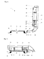
- FIG. 4 shows a vertical longitudinal section corresponding to FIG. 2 through an arrangement with a hybridization chamber 5, wherein the folding frame 54 with the cover 26 of the system 1 inserted therein is unfolded.
- the covers 26 are arranged parallel to each other and in a group of four, because this arrangement just allows a measure of a contact plate 53 of the temperature control thermostat on which a transport frame 52 in the size of a microplate with four parallel to each other slides 27 fits.
- Each of these groups of four is assigned to a contact plate 53 connected to a temperature controller.
- a contact plate 53 is thus designed for planar reception of the four slides 27 of a transport frame 52.
- the frame 52 comprises longitudinal walls, transverse walls and intermediate walls extending substantially parallel to the transverse walls. These walls surround openings which completely penetrate the frame 52, these openings allowing direct contact between the contact plate 53 of the thermostat and the slides 27. Because the slides 27 are held softly in the frame 52 and because the contact plate 53 is formed so that the frame 52 can be slightly lowered toward it, the slides 27 lie directly on the surface of the contact plate 53.
- Each quad of a processing unit comprises one an axis 58 pivotable and lockable relative to a base plate 59 folding frame 54 with four seats, in each of these seats a lid 26 can be inserted.
- Each such process unit also comprises a connection plate 60 for sealingly connecting each of an inlet line 11, outlet line 13 and pressure line 35 of the system 1 with the inlet line 11, outlet line 13 and pressure line 35 of a lid 26.
- As seals for these compounds preferably O arranged on the system side Rings preferred (not shown).
- FIG. 5 shows a vertical longitudinal section corresponding to FIG. 2 through an arrangement with a hybridization chamber 5, wherein the cover 26 of the system inserted into a folding frame 54 is closed. All four hybridization spaces 5 of a group of four defined by a contact plate 53 and such a folding frame 54 are thus associated with the temperature control of a temperature control device.
- Each group of four procedural unit comprises, as described above, a pivotable about an axis 58 and lockable against a base plate 59 folding frame 54 with four seats, wherein in each of these seats, a lid 26 is inserted.
- the folding frame 54 also has a central joint (not shown) with a parallel to the axis 58 mobility. So that the seals 28 close off the hybridization chambers 5 reliably, an additional pressure is exerted on the cover via the snap-on frame 54 26, this can be accomplished via screws, rocker arms or similar known devices (not shown).
- the present invention is based on the recognition that by generating an overpressure in the hybridization chambers 5, the spontaneous occurrence of air bubbles during hybridization can be prevented.
- the chamber pressure should be above the prevailing in the ambient air, normal atmospheric pressure.
- a chamber pressure which is at least 100 mbar to at most 1.4 bar higher than the ambient pressure is preferred. Even higher pressures in the chamber are possible if counteracted by a sufficiently large contact pressure for sealing the chamber.
- the required overpressure in the hybridization chambers 5 can be achieved from one of the vessels 2 by means of a liquid, for example by means of a hybridization medium pressed by the feed pump 8 into the hybridization chambers 5 (see FIG. If a system 1 comprising this hybridization chamber 5 has an agitation device 32 for moving the hybridization media with respect to the immobilized samples, then this system preferably also comprises a spring element which resiliently counteracts the pressure differences generated by the agitation device 32.
- a spring element may be an elastic tube piece (not shown) in a corresponding inlet or outlet to the hybridization chamber 5; but it can also be a spring loaded Expansion vessel (not shown) may be provided, which is connected via a line to the Hybridisierhunt 5.
- inert gas can also be forced out of the container 3 into the distribution line 10 and the inlet lines 11 and the required pressure can be built up via an inlet valve 12 into the hybridization chambers 5 already filled with samples and hybridization media.
- inert gases such as N 2 (nitrogen), which do not undergo any chemical interaction or reactions with the hybridization media. It may also be advantageous if the inert gases are not soluble in the Hybridisiermedien.
- the gas cushion thus constructed which is directly related to the liquid volume used for the hybridization, serves as a spring element for resilient counteraction to the agitation pressure differences. If this is necessary, for example because of a minimal but constant pressure drop across the O-ring seals 28, the required chamber pressure may be sporadically corrected or renewed during the many hours of hybridization.
- one or both of the valves 12, 14 may be kept open for this purpose.
- Another alternative is to use a pressure pump and a pressure vessel (similar to those elements labeled 46 and 47 in FIG. 1) or a gas vessel (such as the N 2 vessel 3 in FIG. 1). to connect to the manifold 15 and to build up the pressure in the Hybridisierhuntn 5 via an opening of the exhaust valves 14.
- An additional alternative to providing a gas cushion serving as a spring member for resiliently counteracting the agitation pressure differentials is that of a pressure pump and a pressure vessel (similar to the elements indicated at 46 and 47 in Fig. 1) or a gas vessel (such as Figs For example, the N 2 tank 3 in Fig. 1) to lead gas into one of the lines which open into at least one of the distribution line 10 or manifold 15.
- one or both of the valves 12, 14 may be kept open.
- the agitator 32 may be used during the preliminary agitation of the hybridization media in the hybridization chambers 5 or even during the hybridization itself.
- simply an agitation pressure in the pressure chamber 34 must be generated, which is higher by about 0.5 to 1 bar than the desired chamber pressure of 100 mbar to 1.4 bar above the ambient pressure.
- the pressure to be used for the agitation moves (depending on the ambient pressure) in the range of approx. 1.6 - 2.4 bar.
- the second diaphragm 33 ' forms in this case a spring element which acts resiliently against this agitation pressure.
- the hybridized samples are dried on the microscope slides 27 by opening only the valves 12, 14 and 21. Then the inert gas valve 50 is opened and the distribution line 10, the inlet lines 11, the Hybridisierhuntn 5, the outlet lines 13 and the manifold 15 through the open relief valve 21, the discharge line 20, the sump 22 and the vent 23 are flushed with inert gas until the samples dry are.
- step c) can be carried out with an inert gas (eg N 2 ):
- an inert gas eg N 2
- chemical interactions between the gaseous spring element N 2 and the samples can be excluded.
- the physical fundamentals were investigated. For this purpose, several 100 slides without samples were processed.
- the basic requirement is of course that the contact pressure on the cover 26, the O-ring 28 and the slide 27 is sufficiently large, ie, significantly higher than the chamber pressure generated.
- the hybridization chambers 5 used comprised between the cover 26 and the slide 27 an area of 21 ⁇ 65 mm. The chamber pressure was increased by 1 bar, ie by 10 5 N / m 2 above the normal pressure of the environment.
- the hybridization procedure (buffer preparation, pattern injection, program definition on the hybridization systems used) was carried out according to the technical instructions of Alopex (ALOPEX GmbH, Fritz-Hornschuch-Str. 9, D-95326 Kulmbach, Federal Republic of Germany). In each case two slides 27 were inserted into the hybridization systems SN22 and PT3 and processed at 43 ° C. or at 61 ° C.
- results show not only that both devices used give very useful results. Rather, the results obtained in the two devices SN22 and PT3 (ordered by temperature) are so similar to each other that an influence of the increased pressure on the hybridization can be excluded.
- inventive method is not limited to the use in hybridization. It can also be used in other devices or used to prevent the occurrence of unwanted air bubbles. Such devices or instruments may e.g. from the field of microfluidics technology, such as "lab on a chip” systems.
- FIG. 6 shows a diagram of a second device or system suitable for carrying out the method according to the invention.
- This system 1 'differs from the system 1 shown in FIG. 1 essentially in that each lid 26 is assigned two hybridizing chambers 5A, 5B. These two hybridization chambers 5A, 5B can be arranged over a single slide with, for example, two identical DNA microarrays. However, it is also possible to use two smaller slides 27, each of which together with one cover 26 only defines one hybridization chamber 5 (not shown).
- Each Hybridisierhunt 5A, 5B is supplied by the distribution line 10 via a respective individual inlet valve 12A, 12B and one individual inlet line 11A, 11B with liquids, such as washing buffer or Hybridisiermedien.
- all Hybridisierhuntn either self-sufficient, ie independently or jointly, ie operated simultaneously.
- each cover 26 of this particularly preferred system 1 has its own hybridization chamber 5A, 5B each with its own
- This agitation space 30 is in each case connected to an agitation line 36 with the hybridization chamber 5A, 5B, wherein the membrane 33 separates the agitation space 30 from a pressure space 34.
- These pressure chambers 34 are filled via the pressure line 35 with a pressurized fluid and sporadically, for example, acted upon pulsating with the agitation pressure.
- the membranes 33 of the hybridization chambers 5A, 5B are charged in series, i. synchronous.
- each diaphragm 33 is pressurized with a separate pressure line 35 (parallel) (not shown).
- outlets 13A, 13B of a lid 26 open into the outlet 13 of the same and are, as already described in Figure 1, supplied via the outlet valve 14 of the manifold 15.
- the outlet duct 13 has an enlarged diameter and thus provides the space in which a gas cushion serving as a spring element can be accommodated.
- This spring element is - directly via a continuous fluid line, or indirectly (separated by a membrane) - in communication with the volume of liquid used for the hybridization.
- This spring element resiliently counteracts the agitation pressure differences exerted by the agitation device 32 on the pressure chamber 34 (similar to what has already been described in connection with FIG. 1).
- a spring element - no matter how it is formed - is preferably elastic or compressible or stretchable and compensates for the Agitations réelleunter Kunststoffe in the Hybridisierhuntn 5, so that the chamber pressure over a certain time, for example during the entire hybridization, so far above that in the ambient air prevailing, normal atmospheric pressure is that in the Hybridisiermedium no gas bubbles can form.
- the preferred system 1 comprises a blow line 62, which via a blow valve 63 preferably leads straight to the point where the outlet 13B opens into the outlet line 13.
- This blow line 62 is operated as follows: First, each hybridization chamber 5A, 5B is filled with wash buffer. In this case, the inlet lines 11A, 11B and the outlets 13A, 13B and the outlet 13 are also filled with washing buffer. After the sample liquids are pipetted in, the pattern feeders 31 and the inlet valves 12A, 12B are closed again. The exhaust valves 14 remain open. If the blow valves 63 are now opened, gas from a compressor or a pressure accumulator flows via the individual blow lines 64 into the outlet lines 13 and displaces the wash buffer from these outlet lines 13. This gas then forms the gas cushion in the outlet line 13 , The gas cushion has the necessary volume to successfully serve as a spring element.
- the spring element can be regarded as part of the Agitationsmechanismus; in fact, it is not necessary here to attach a second membrane 33 '. However, if the cross section of the outlet 13 is too small, In order to make available the entire space required for the spring element effect, a second membrane 33 '(cf., for example, FIG. 1) can additionally be provided.
- Figure 7 shows a schematic view of a particular, first arrangement of a lid 26 with a hybridization chamber 5, seen from below.
- the essential difference from the embodiment already shown in FIG. 3 lies here in the outlet conduit 13 with the enlarged diameter, whereby the space for a gas cushion serving as a spring element is made available.
- the individual outlet 13 'of the hybridization chamber 5 opens into this outlet line 13 in the vicinity of its end.
- the individual blow line 64 assigned to this hybridization chamber 5 also discharges in the same region.
- All media lines each have a connection opening which is located in the common connection plane 57 of the Cover 26 is located. These five openings are preferably arranged on a line, but they can also be arranged arbitrarily. All other parts correspond to the embodiment of Fig. 3.
- a second membrane 33 ' is provided, which closes a second agitation space 30'.
- the second diaphragm 33 'in this case serves to support the spring element arranged as a gas cushion in the outlet line 13.
- FIG. 8 shows a schematic view of a particular, second arrangement of a lid 26 with two Hybridisierhuntn 5A, 5B, seen from below.
- the cover 26 has an outlet duct 13 with the enlarged diameter, whereby the space for a gas cushion serving as a spring element is made available.
- the provided cavity is sufficient to guarantee the effect as a spring element, therefore, both hybridization chambers 5A, 5B lying behind one another have no second membrane 33 'and no second agitation space 30'.
- the two individual outlets 13A, 13B open into this outlet line 13, wherein an orifice near the end and the other mouth is located somewhere in a central region of the outlet duct 13.
- the agitation in the Hybridisierhuntn 5A, 5B is operated via a common Agitations effet 35.
- an individual agitation line may each lead to the agitation chambers 30 of the two hybridization chambers 5A, 5B (not shown).
- the pressure line 35 could branch within the lid, so that only one common connection for the individual pressure lines on the common connection plane 57 of the lid 26 would be necessary.
- it could also be provided to provide the two hybridization chambers 5A, 5B each with an individual and independent agitation device 32. This would be accomplished with an additional pressure line 42 'and pressure distribution line 39' and with an individual agitation line 35 'which can be filled per hybridization chamber 5A, 5B via an additional connection in the common connection plane 57 of the cover 26 (not shown).
- a single slide 27 may have a plurality of regions preferably provided with a nucleotide array, so that a plurality of hybridization chambers 5 per cover 26 and slide 27 may be operated with a divided cover 26 (see for example Fig. 8).
- smaller slides 27 ' may also be provided which essentially define just a single, smaller hybridization chamber 5 so that the plurality of hybridization chambers 5 per cover 26, but on a plurality of slides 27, can be operated.
Landscapes
- Chemical & Material Sciences (AREA)
- Chemical Kinetics & Catalysis (AREA)
- Health & Medical Sciences (AREA)
- Dispersion Chemistry (AREA)
- Analytical Chemistry (AREA)
- General Health & Medical Sciences (AREA)
- Hematology (AREA)
- Clinical Laboratory Science (AREA)
- Apparatus Associated With Microorganisms And Enzymes (AREA)
- Degasification And Air Bubble Elimination (AREA)
Priority Applications (1)
| Application Number | Priority Date | Filing Date | Title |
|---|---|---|---|
| EP10172196.7A EP2255880B1 (fr) | 2005-06-21 | 2005-06-21 | Dispositif et procédé pour la prévention de bulles d'air dans une chambre d'hybridation |
Applications Claiming Priority (3)
| Application Number | Priority Date | Filing Date | Title |
|---|---|---|---|
| CH11442004 | 2004-07-08 | ||
| DE202004012163U DE202004012163U1 (de) | 2004-07-08 | 2004-08-04 | System mit Einrichtung zum Verhindern von Luftblasen in einer Hybridisierkammer |
| US10/931,432 US7615370B2 (en) | 2004-07-08 | 2004-09-01 | System having device for preventing air bubbles in a hybridization chamber and corresponding method |
Related Child Applications (1)
| Application Number | Title | Priority Date | Filing Date |
|---|---|---|---|
| EP10172196.7A Division EP2255880B1 (fr) | 2005-06-21 | 2005-06-21 | Dispositif et procédé pour la prévention de bulles d'air dans une chambre d'hybridation |
Publications (2)
| Publication Number | Publication Date |
|---|---|
| EP1614466A2 true EP1614466A2 (fr) | 2006-01-11 |
| EP1614466A3 EP1614466A3 (fr) | 2006-05-10 |
Family
ID=35106752
Family Applications (1)
| Application Number | Title | Priority Date | Filing Date |
|---|---|---|---|
| EP05105498A Ceased EP1614466A3 (fr) | 2004-07-08 | 2005-06-21 | Dispositif et procédé pour la prévention de bulles d'air dans une chambre d'hybridation |
Country Status (2)
| Country | Link |
|---|---|
| EP (1) | EP1614466A3 (fr) |
| JP (1) | JP4819421B2 (fr) |
Cited By (9)
| Publication number | Priority date | Publication date | Assignee | Title |
|---|---|---|---|---|
| WO2008098094A1 (fr) * | 2007-02-06 | 2008-08-14 | Network Biosystems, Inc. | Dispositifs et procédés pour effectuer des dosages in vitro miniaturisés |
| EP2186565A1 (fr) | 2008-11-13 | 2010-05-19 | Tecan Trading AG | Appareil de mesure et procédé de détermination de paramètres de fluide préparés par un système de laboratoire |
| WO2011006177A1 (fr) * | 2009-07-15 | 2011-01-20 | Ait Austrian Institute Of Technology Gmbh | Porte-échantillons |
| US8425861B2 (en) | 2007-04-04 | 2013-04-23 | Netbio, Inc. | Methods for rapid multiplexed amplification of target nucleic acids |
| US9550985B2 (en) | 2009-06-15 | 2017-01-24 | Netbio, Inc. | Methods for forensic DNA quantitation |
| CN108431199A (zh) * | 2016-01-05 | 2018-08-21 | 日本板硝子株式会社 | 反应处理装置、反应处理容器、反应处理方法 |
| CN112683801A (zh) * | 2021-01-21 | 2021-04-20 | 上海菁一科技有限公司 | 一种分光光度测试法样品处理测试胶囊 |
| CN114289091A (zh) * | 2022-01-18 | 2022-04-08 | 四川沃文特生物技术有限公司 | 一种用于自动分析设备制冷系统的缓冲罐 |
| EP4046717A3 (fr) * | 2015-05-29 | 2022-12-14 | Illumina, Inc. | Support d'échantillons et système d'analyse pour réaliser des réactions désignées |
Families Citing this family (9)
| Publication number | Priority date | Publication date | Assignee | Title |
|---|---|---|---|---|
| CA2786569C (fr) | 2010-01-29 | 2019-04-09 | Perkinelmer Health Sciences, Inc. | Cartouche microfluidique «de l'echantillon au resultat» |
| JP6190822B2 (ja) * | 2012-01-09 | 2017-08-30 | マイクロニクス, インコーポレイテッド | マイクロ流体リアクタシステム |
| CN104919035B (zh) | 2012-12-21 | 2017-08-11 | 精密公司 | 便携式荧光检测系统和微测定盒 |
| JP6498125B2 (ja) | 2012-12-21 | 2019-04-10 | マイクロニクス, インコーポレイテッド | 流体回路および関連する製造方法 |
| KR20150096788A (ko) | 2012-12-21 | 2015-08-25 | 마이크로닉스 인코포레이티드. | 마이크로 유체공학 용도를 위한 저탄성 막 |
| EP2994543B1 (fr) | 2013-05-07 | 2018-08-15 | Micronics, Inc. | Dispositif pour la préparation et l'analyse d'acides nucléiques |
| WO2014182844A1 (fr) | 2013-05-07 | 2014-11-13 | Micronics, Inc. | Dispositifs microfluidiques et méthodes de séparation du sérum et de compatibilité croisée du sang |
| CA2911303C (fr) | 2013-05-07 | 2021-02-16 | Micronics, Inc. | Procedes de preparation d'echantillons d'acides nucleiques faisant appel a des mineraux argileux et a des solutions alcalines |
| WO2025028342A1 (fr) * | 2023-07-28 | 2025-02-06 | 株式会社Mirai Genomics | Cuve de réaction pour l'amplification d'acides nucléiques, cartouche, dispositif et procédé de traitement par amplification d'acides nucléiques |
Family Cites Families (5)
| Publication number | Priority date | Publication date | Assignee | Title |
|---|---|---|---|---|
| US6948843B2 (en) * | 1998-10-28 | 2005-09-27 | Covaris, Inc. | Method and apparatus for acoustically controlling liquid solutions in microfluidic devices |
| WO2001088204A1 (fr) * | 2000-05-15 | 2001-11-22 | Biomicro Systems, Inc. | Regulation de l'ecoulement d'air dans des circuits microfluidiques destinee au reglage de la pression et a l'echange de gaz |
| EP1524028B1 (fr) * | 2001-05-25 | 2008-09-24 | Tecan Trading AG | Appareil et set de traitament pour la préparation d'une chambre d'hybridation |
| US6684966B2 (en) * | 2001-10-18 | 2004-02-03 | Baker Hughes Incorporated | PCD face seal for earth-boring bit |
| DE10258398A1 (de) * | 2002-12-11 | 2004-08-12 | Hans-Knöll-Institut für Naturstoff-Forschung e.V. | Verfahren zur Amplifikation von DNA |
-
2005
- 2005-06-21 EP EP05105498A patent/EP1614466A3/fr not_active Ceased
- 2005-07-08 JP JP2005200121A patent/JP4819421B2/ja not_active Expired - Fee Related
Non-Patent Citations (1)
| Title |
|---|
| None |
Cited By (18)
| Publication number | Priority date | Publication date | Assignee | Title |
|---|---|---|---|---|
| WO2008098094A1 (fr) * | 2007-02-06 | 2008-08-14 | Network Biosystems, Inc. | Dispositifs et procédés pour effectuer des dosages in vitro miniaturisés |
| US9494519B2 (en) | 2007-04-04 | 2016-11-15 | Netbio, Inc. | Methods for rapid multiplexed amplification of target nucleic acids |
| US8425861B2 (en) | 2007-04-04 | 2013-04-23 | Netbio, Inc. | Methods for rapid multiplexed amplification of target nucleic acids |
| EP2186565A1 (fr) | 2008-11-13 | 2010-05-19 | Tecan Trading AG | Appareil de mesure et procédé de détermination de paramètres de fluide préparés par un système de laboratoire |
| US10538804B2 (en) | 2009-06-15 | 2020-01-21 | Ande Corporation | Methods for forensic DNA quantitation |
| US9550985B2 (en) | 2009-06-15 | 2017-01-24 | Netbio, Inc. | Methods for forensic DNA quantitation |
| US11441173B2 (en) | 2009-06-15 | 2022-09-13 | Ande Corporation | Optical instruments and systems for forensic DNA quantitation |
| WO2011006177A1 (fr) * | 2009-07-15 | 2011-01-20 | Ait Austrian Institute Of Technology Gmbh | Porte-échantillons |
| EP4046717A3 (fr) * | 2015-05-29 | 2022-12-14 | Illumina, Inc. | Support d'échantillons et système d'analyse pour réaliser des réactions désignées |
| US12076725B2 (en) | 2015-05-29 | 2024-09-03 | Illumina, Inc. | Fluidic device and method for preparing a sample substrate |
| CN108431199B (zh) * | 2016-01-05 | 2022-04-08 | 日本板硝子株式会社 | 反应处理装置和反应处理方法 |
| US11351552B2 (en) | 2016-01-05 | 2022-06-07 | Nippon Sheet Glass Company, Limited | Reaction processor, reaction processing vessel, and reaction processing method |
| EP3401386A4 (fr) * | 2016-01-05 | 2019-12-25 | Nippon Sheet Glass Company, Limited | Dispositif de traitement réactionnel, contenant de traitement réactionnel, et procédé de traitement réactionnel |
| CN108431199A (zh) * | 2016-01-05 | 2018-08-21 | 日本板硝子株式会社 | 反应处理装置、反应处理容器、反应处理方法 |
| CN112683801A (zh) * | 2021-01-21 | 2021-04-20 | 上海菁一科技有限公司 | 一种分光光度测试法样品处理测试胶囊 |
| CN112683801B (zh) * | 2021-01-21 | 2023-04-28 | 上海菁一科技有限公司 | 一种分光光度测试法样品处理测试胶囊 |
| CN114289091A (zh) * | 2022-01-18 | 2022-04-08 | 四川沃文特生物技术有限公司 | 一种用于自动分析设备制冷系统的缓冲罐 |
| CN114289091B (zh) * | 2022-01-18 | 2023-03-28 | 四川沃文特生物技术有限公司 | 一种用于自动分析设备制冷系统的缓冲罐 |
Also Published As
| Publication number | Publication date |
|---|---|
| EP1614466A3 (fr) | 2006-05-10 |
| JP4819421B2 (ja) | 2011-11-24 |
| JP2006084459A (ja) | 2006-03-30 |
Similar Documents
| Publication | Publication Date | Title |
|---|---|---|
| EP1614466A2 (fr) | Dispositif et procédé pour la prévention de bulles d'air dans une chambre d'hybridation | |
| EP1260265B1 (fr) | Système avec un set de traitament pour l'hybridation d'échantillons d'acide nucléique, protéines et tissus | |
| DE69509925T3 (de) | Verfahren und vorrichtung zur herstellung von mikromatrizen für biologische proben | |
| DE202004012163U1 (de) | System mit Einrichtung zum Verhindern von Luftblasen in einer Hybridisierkammer | |
| DE60307645T2 (de) | Hoch-durchsatz assay zur messung von zellulären antworten mit hilfe von mikroarrays | |
| DE10011022A1 (de) | Vorrichtung und Verfahren zur Durchführung von Synthesen, Analysen oder Transportvorgängen | |
| WO2003025113A2 (fr) | Procede pour cultiver et analyser des cultures de cellules individuelles microbiennes | |
| US7615370B2 (en) | System having device for preventing air bubbles in a hybridization chamber and corresponding method | |
| EP2255880B1 (fr) | Dispositif et procédé pour la prévention de bulles d'air dans une chambre d'hybridation | |
| DE202004011272U1 (de) | Vorrichtung zum Bereitstellen einer Hybridisierkammer und zum Beeinflussen von Luftblasen in derselben | |
| DE69221479T2 (de) | Verfahren zur bildung einer matrix von biologischen teilchen | |
| DE112008003552T9 (de) | Thermozykler-Instrument und Verfahren zur Durchführung von PCR | |
| EP3609995B1 (fr) | Procédé de traitement d'un échantillon liquide | |
| DE112006000361B4 (de) | Verfahren zur Einführung und Überführung einer Vielzahl kleinster Probenmengen | |
| DE10346451B4 (de) | Verfahren zur Überwachung von Veränderungen und Zuständen in Reaktionskammern | |
| EP2126540B1 (fr) | Dispositif et système de conditionnement sous gaz | |
| DE112018007861T5 (de) | Biochemische Kassette und biochemische Analysevorrichtung | |
| EP2186565A1 (fr) | Appareil de mesure et procédé de détermination de paramètres de fluide préparés par un système de laboratoire | |
| EP1616619A1 (fr) | Dispositf et procédé ayant une influence sur bulles d'air dans une chambre hybridation | |
| EP1287328B1 (fr) | Dispositif et procede de traitement de prelevements lies a un substrat | |
| EP4123600A1 (fr) | Procédé de détection d'une particule dans un récipient rempli de liquide | |
| WO2001090721A1 (fr) | Procede et dispositif pour reguler l'echange de matiere entre un echantillon et l'atmosphere entourant l'echantillon | |
| WO2009132616A2 (fr) | Système d'amenée | |
| DE20220299U1 (de) | Biochip-Reader | |
| WO2003106032A1 (fr) | Chambre d'hybridation |
Legal Events
| Date | Code | Title | Description |
|---|---|---|---|
| PUAI | Public reference made under article 153(3) epc to a published international application that has entered the european phase |
Free format text: ORIGINAL CODE: 0009012 |
|
| AK | Designated contracting states |
Kind code of ref document: A2 Designated state(s): AT BE BG CH CY CZ DE DK EE ES FI FR GB GR HU IE IS IT LI LT LU MC NL PL PT RO SE SI SK TR |
|
| AX | Request for extension of the european patent |
Extension state: AL BA HR LV MK YU |
|
| 17P | Request for examination filed |
Effective date: 20051212 |
|
| PUAL | Search report despatched |
Free format text: ORIGINAL CODE: 0009013 |
|
| AK | Designated contracting states |
Kind code of ref document: A3 Designated state(s): AT BE BG CH CY CZ DE DK EE ES FI FR GB GR HU IE IS IT LI LT LU MC NL PL PT RO SE SI SK TR |
|
| AX | Request for extension of the european patent |
Extension state: AL BA HR LV MK YU |
|
| AKX | Designation fees paid |
Designated state(s): CH DE FR GB LI |
|
| 17Q | First examination report despatched |
Effective date: 20070710 |
|
| APBK | Appeal reference recorded |
Free format text: ORIGINAL CODE: EPIDOSNREFNE |
|
| APBN | Date of receipt of notice of appeal recorded |
Free format text: ORIGINAL CODE: EPIDOSNNOA2E |
|
| APAV | Appeal reference deleted |
Free format text: ORIGINAL CODE: EPIDOSDREFNE |
|
| APBT | Appeal procedure closed |
Free format text: ORIGINAL CODE: EPIDOSNNOA9E |
|
| STAA | Information on the status of an ep patent application or granted ep patent |
Free format text: STATUS: THE APPLICATION HAS BEEN REFUSED |
|
| 18R | Application refused |
Effective date: 20100824 |