EP1614481A2 - Einheit mit einer umkehrbaren Düse - Google Patents
Einheit mit einer umkehrbaren Düse Download PDFInfo
- Publication number
- EP1614481A2 EP1614481A2 EP05253447A EP05253447A EP1614481A2 EP 1614481 A2 EP1614481 A2 EP 1614481A2 EP 05253447 A EP05253447 A EP 05253447A EP 05253447 A EP05253447 A EP 05253447A EP 1614481 A2 EP1614481 A2 EP 1614481A2
- Authority
- EP
- European Patent Office
- Prior art keywords
- spray tip
- bore
- turret member
- saddle seal
- housing
- Prior art date
- Legal status (The legal status is an assumption and is not a legal conclusion. Google has not performed a legal analysis and makes no representation as to the accuracy of the status listed.)
- Granted
Links
Images




Classifications
-
- B—PERFORMING OPERATIONS; TRANSPORTING
- B05—SPRAYING OR ATOMISING IN GENERAL; APPLYING FLUENT MATERIALS TO SURFACES, IN GENERAL
- B05B—SPRAYING APPARATUS; ATOMISING APPARATUS; NOZZLES
- B05B15/00—Details of spraying plant or spraying apparatus not otherwise provided for; Accessories
- B05B15/50—Arrangements for cleaning; Arrangements for preventing deposits, drying-out or blockage; Arrangements for detecting improper discharge caused by the presence of foreign matter
- B05B15/52—Arrangements for cleaning; Arrangements for preventing deposits, drying-out or blockage; Arrangements for detecting improper discharge caused by the presence of foreign matter for removal of clogging particles
- B05B15/531—Arrangements for cleaning; Arrangements for preventing deposits, drying-out or blockage; Arrangements for detecting improper discharge caused by the presence of foreign matter for removal of clogging particles using backflow
- B05B15/534—Arrangements for cleaning; Arrangements for preventing deposits, drying-out or blockage; Arrangements for detecting improper discharge caused by the presence of foreign matter for removal of clogging particles using backflow by reversing the nozzle relative to the supply conduit
-
- Y—GENERAL TAGGING OF NEW TECHNOLOGICAL DEVELOPMENTS; GENERAL TAGGING OF CROSS-SECTIONAL TECHNOLOGIES SPANNING OVER SEVERAL SECTIONS OF THE IPC; TECHNICAL SUBJECTS COVERED BY FORMER USPC CROSS-REFERENCE ART COLLECTIONS [XRACs] AND DIGESTS
- Y10—TECHNICAL SUBJECTS COVERED BY FORMER USPC
- Y10T—TECHNICAL SUBJECTS COVERED BY FORMER US CLASSIFICATION
- Y10T29/00—Metal working
- Y10T29/49—Method of mechanical manufacture
- Y10T29/49428—Gas and water specific plumbing component making
- Y10T29/49432—Nozzle making
- Y10T29/49433—Sprayer
-
- Y—GENERAL TAGGING OF NEW TECHNOLOGICAL DEVELOPMENTS; GENERAL TAGGING OF CROSS-SECTIONAL TECHNOLOGIES SPANNING OVER SEVERAL SECTIONS OF THE IPC; TECHNICAL SUBJECTS COVERED BY FORMER USPC CROSS-REFERENCE ART COLLECTIONS [XRACs] AND DIGESTS
- Y10—TECHNICAL SUBJECTS COVERED BY FORMER USPC
- Y10T—TECHNICAL SUBJECTS COVERED BY FORMER US CLASSIFICATION
- Y10T29/00—Metal working
- Y10T29/49—Method of mechanical manufacture
- Y10T29/49826—Assembling or joining
- Y10T29/49895—Associating parts by use of aligning means [e.g., use of a drift pin or a "fixture"]
- Y10T29/49901—Sequentially associating parts on stationary aligning means
-
- Y—GENERAL TAGGING OF NEW TECHNOLOGICAL DEVELOPMENTS; GENERAL TAGGING OF CROSS-SECTIONAL TECHNOLOGIES SPANNING OVER SEVERAL SECTIONS OF THE IPC; TECHNICAL SUBJECTS COVERED BY FORMER USPC CROSS-REFERENCE ART COLLECTIONS [XRACs] AND DIGESTS
- Y10—TECHNICAL SUBJECTS COVERED BY FORMER USPC
- Y10T—TECHNICAL SUBJECTS COVERED BY FORMER US CLASSIFICATION
- Y10T29/00—Metal working
- Y10T29/53—Means to assemble or disassemble
- Y10T29/53978—Means to assemble or disassemble including means to relatively position plural work parts
Definitions
- the present invention relates generally to spray tips for use in spray guns used in the hydraulic atomization and spraying of liquids such as paint wherein the spray tip is reversible so that obstructions therein which clog the spray tip may be easily removed by the reversed flow of the high pressure liquid paint there-through. More particularly, the present invention relates to a means for quickly and accurately assembling a disassembled reversible spray tip unit.
- the reversible spray tip unit or assembly with which the present invention is concerned is used in hydraulic or airless paint spraying and generally consists of a rotatable cylindrically shaped turret member arranged transverse to the flow of high pressure paint wherein a diametric fluid bore is provided for mounting of the spray tip or nozzle.
- a housing for the reversible spray tip unit is engaged by a securing nut which secures the spray tip unit to the discharge end of the spray gun.
- the spray tip unit housing permits the turret member to be axially rotated therein so as to present the spray tip forwardly for spray painting and rearwardly facing the discharge end of the spray gun so that clogs in the spray tip can be removed by the reversed flow of paint.
- a metallic, socalled saddle seal is received in an axial bore therefor in the spray tip unit housing so as to contact the face of the cylindrically shaped turret member at the diametric fluid bore therein.
- the sealing face of the saddle seal has a shape which is complementary to the cylindrical shape of the turret member and upstream therefrom an elastomeric sealing washer is arranged on the saddle seal which is compressed against the discharge end of the spray gun by the tightening of the securing nut.
- An axial fluid bore provided in the saddle seal delivers the high pressure fluid paint from the spray gun discharge to the fluid bore in the turret member.
- the spray tip unit housing is generally surrounded by a plastic tip guard having Y or V shaped forward extending ears.
- the turret member is provided with a T-shaped handle so that it may be easily rotated as required.
- the present invention seeks to overcome the prior art disadvantages and to provide an improved spray tip unit. More particularly, the present invention seeks to provide a reversible spray tip unit for an airless spray gun having an axially rotatable cylindrically shaped turret member with the spray tip nozzle arranged in a diametric fluid bore therein, the turret member being disposed in a complementary shaped bore of the unit housing and arranged transverse to the flow of paint, and a saddle seal received axially in the housing and having a cylindrically shaped sealing face mating with the cylindrical shape of the turret member at the diametric fluid bore housing the spray tip nozzle, wherein upon assembly of the disassembled reversible spray tip unit, the saddle seal can be quickly inserted and precisely oriented to align the cylindrically shaped sealing face thereof with the cylindrically shaped bore in the housing for the turret member so that the turret member can be received in the housing bore therefor.
- a reversible spray tip unit adapted to be secured to the discharge end of a spray gun for hydraulically atomizing and spraying liquid paint
- the spray tip unit including a spray tip unit housing, an axially rotatable cylindrically shaped turret member with a spray tip nozzle arranged in a diametric fluid bore therein, the turret member being disposed in a complementary shaped bore of the unit housing arranged transverse to the flow of paint and having a T-shaped handle at an end of the turret member for the rotation thereof, and a cylindrically shaped saddle seal received in an axial bore in the unit housing and having a cylindrically shaped sealing face mating with the cylindrical shape of the turret member at the diametric fluid bore housing the spray tip nozzle, the saddle seal being provided with an axial fluid bore for communication between the spray gun discharge and the rotatable turret member, characterised in that it further comprises:
- the fluid bore of the saddle seal is provided in the form of a keyway or key seat adapted to receive therein the key of an insertion/orientation tool.
- the insertion/orientation tool is provided for inserting the saddle seal into the saddle seal bore of the housing and because it is keyed to the fluid bore thereof, the saddle seal can be easily oriented within the saddle seal bore by the rotation of the insertion/orientation tool in the manner of a key which axially rotates the saddle seal within the bore therefor.
- the key of the insertion/orientation tool is formed as part of the turret member and preferably as one of the ends of the top cross member of the T-shaped handle and is arranged thereon so that when keyed to the fluid bore of the saddle seal the axial direction of the cylindrically shaped sealing face of the saddle seal is aligned with the axial direction of the turret member.
- the alignment of the sealing face of the saddle seal with the turret member bore of the housing is easily accomplished by aligning the axial direction of the turret member connected to the T-shaped handle therefor parallel with the axial direction of the turret member bore of the housing.
- the insertion/orientation tool is formed as part of said turret member/T-shaped handle combination.
- the insertion/orientation tool is formed on an end of said turret member opposite the end of said turret member having said T-shaped handle.
- said insertion/orientation tool is formed as one end of the top cross member of said T-shaped handle of the turret member.
- the top cross member of said T-shaped handle is preferably shaped as an arrow which points in the direction of exit from the spray tip nozzle and said insertion/orientation tool is located at the tip of said arrow.
- the key of said insertion/orientation tool is preferably arranged so that when keyed with the keyway of the fluid bore of said saddle seal, the axial direction of the cylindrically shaped sealing face of the saddle seal is parallel to the axial direction of the cylindrically shaped turret member.
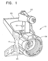
- FIGS. 1 and 2 there is shown in FIGS. 1 and 2, a reversible spray tip unit, generally designated 10, including a turret member 12, a spray tip unit housing 14 and a saddle seal 16.
- Turret member 12 includes a barrel shaped portion, designated 18, to an end of which is attached a T-shaped handle 20.
- Barrel portion 18 has a diametric through bore 22 formed therein at one end of which is housed the spray tip nozzle (not shown).
- the top cross member 24 of the T-shaped handle 20 is in alignment with bore 22 and advantageously, cross member 24 is provided with the general shape of an arrow wherein the point of the arrow indicates the exit direction of the spray tip nozzle.
- cross member 24 is provided with the general shape of an arrow wherein the point of the arrow indicates the exit direction of the spray tip nozzle.
- the arrow shape of cross member 24 is pointed rearwardly indicating that the spray tip nozzle housed in turret member 12 is in reversed position facing the discharge end of a spray gun (not shown) to which reversible spray tip unit 10 is attached for clearing any clogs therein.
- Spray tip unit housing 14 is provided with V or Y-shaped tip guard 26 and a securing nut 28 for securing the reversible spray tip unit 10 to the forward or discharge end of the spray gun.
- a cylindrically shaped transverse bore 30 is formed in housing 14, as clearly seen in Fig. 4, to receive barrel portion 18 of turret member 12 therein.
- An axial through bore 32 is provided in housing 14 in alignment with the spray gun discharge and in alignment with fluid bore 22 of turret member 12 when barrel 18 thereof is seated in bore 30 of housing 14.
- Saddle seal 16 as clearly seen in FIG. 2, is received in the upstream end of bore 32 of housing 14 and when properly seated therein its cylindrically shaped sealing face 34 aligns with bore 30 as seen in FIG. 4.
- Saddle seal 16 is provided at its upstream end in contact with the discharge end of the spray gun with a resilient sealing washer 36 and has an axial fluid bore 38 therein which aligns with fluid bore 22 of turret member 12 when the reversible spray tip unit 10 is fully assembled.
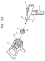
- FIGS. 5A to 5D show in accordance with the present invention, how saddle seal 16 is inserted into bore 32 of housing 14 and oriented therein so that the cylindrically shaped sealing face 34 thereof can be easily and accurately aligned with bore 30 of housing 14 as shown in Fig. 4.
- fluid bore 38 of saddle seal 16 is shaped as a keyway or key seat so as to be keyed to key 40 of an insertion/orientation tool 42 so that the orientation of saddle seal 16 within bore 32 of housing 14 can be easily adjusted by rotating or turning tool 42 which in turn rotates saddle seal 16.
- the insertion/orientation tool 42 is advantageously formed as part of turret member 12 and preferably it is formed at one end of top cross member 24 of T-shaped handle 20.
- Key 40 of insertion/orientation tool 42 is oriented so that when it engages with and is keyed to the keyway of fluid bore 38, as clearly seen in FIG. 5B, the axial direction of cylindrically shaped sealing face 34 of saddle seal 16 is parallel to the axial direction of barrel 18 of turret member 12.
- sealing face 34 can be aligned with bore 30 of housing 14 in one of two ways. The first is by visually sighting down bore 30 and axially adjusting the orientation of saddle seal 16 by turning turret member 12 in the direction of arrow A until sealing face 34 aligns with bore 30.
- the second way for accurately aligning sealing face 34 of saddle seal 16 with bore 30 is by aligning barrel 18 of turret member 12 parallel to bore 30 prior to insertion of the saddle seal whereby the axial direction of cylindrically shaped sealing face 34 is parallel to the axial direction of bore 30 of housing 14 and then inserting the properly oriented saddle seal.
- FIG. 6 shows another arrangement of the insertion/orientation tool whereby insertion/orientation tool 142 is arranged at an end of barrel shaped portion 18 of turret member 12 opposite T-shaped handle 20.
- key 140 of insertion/orientation tool 142 is disposed axially at the end of barrel shaped portion 18.
- insertion/orientation tool 142 operates in the same manner as insertion/orientation tool 42, described above.
Landscapes
- Details Or Accessories Of Spraying Plant Or Apparatus (AREA)
- Nozzles (AREA)
- Spray Control Apparatus (AREA)
- Containers And Packaging Bodies Having A Special Means To Remove Contents (AREA)
- Catching Or Destruction (AREA)
- Percussion Or Vibration Massage (AREA)
Applications Claiming Priority (1)
| Application Number | Priority Date | Filing Date | Title |
|---|---|---|---|
| US10/886,857 US6978944B1 (en) | 2004-07-08 | 2004-07-08 | Reversible spray tip unit |
Publications (4)
| Publication Number | Publication Date |
|---|---|
| EP1614481A2 true EP1614481A2 (de) | 2006-01-11 |
| EP1614481A3 EP1614481A3 (de) | 2006-12-27 |
| EP1614481B1 EP1614481B1 (de) | 2008-04-16 |
| EP1614481B8 EP1614481B8 (de) | 2008-07-16 |
Family
ID=34981752
Family Applications (1)
| Application Number | Title | Priority Date | Filing Date |
|---|---|---|---|
| EP05253447A Expired - Lifetime EP1614481B8 (de) | 2004-07-08 | 2005-06-03 | Einheit mit einer umkehrbaren Düse |
Country Status (7)
| Country | Link |
|---|---|
| US (1) | US6978944B1 (de) |
| EP (1) | EP1614481B8 (de) |
| AT (1) | ATE392265T1 (de) |
| AU (1) | AU2005201673B2 (de) |
| DE (1) | DE602005006050T2 (de) |
| DK (1) | DK1614481T3 (de) |
| ES (1) | ES2303194T3 (de) |
Families Citing this family (19)
| Publication number | Priority date | Publication date | Assignee | Title |
|---|---|---|---|---|
| US8596555B2 (en) | 2008-10-22 | 2013-12-03 | Graco Minnesota Inc. | Portable airless sprayer |
| USD666274S1 (en) * | 2011-11-23 | 2012-08-28 | Wagner Spray Tech Corporation | Fluid spray tip |
| USD665477S1 (en) * | 2011-11-23 | 2012-08-14 | Wagner Spray Tech Corporation | Fluid spray tip guard |
| USD796003S1 (en) | 2016-06-15 | 2017-08-29 | Wagner Spray Tech Corporation | Paint spray gun tip |
| EP3774069A1 (de) | 2018-04-10 | 2021-02-17 | Graco Minnesota Inc. | Tragbare luftlose sprühvorrichtung für farben und andere beschichtungen |
| CN108405205B (zh) * | 2018-05-04 | 2023-12-19 | 钱滋勒贸易(上海)有限公司 | 高压无气喷嘴 |
| USD908835S1 (en) * | 2019-01-17 | 2021-01-26 | Graco Minnesota Inc. | Spray tip |
| TWI855085B (zh) | 2019-05-31 | 2024-09-11 | 美商葛萊兒明尼蘇達股份有限公司 | 手持式流體噴霧器 |
| USD925696S1 (en) * | 2020-01-28 | 2021-07-20 | Harbor Freight Tools Usa, Inc. | Reversible tip flag for use with a paint sprayer |
| US20210283640A1 (en) * | 2020-03-11 | 2021-09-16 | Harbor Freight Tools Usa, Inc. | Paint sprayer saddle seal insertion tool and method |
| USD1047080S1 (en) * | 2020-04-29 | 2024-10-15 | Ac Avalanche, Llc | Dispenser housing |
| US10968903B1 (en) | 2020-06-04 | 2021-04-06 | Graco Minnesota Inc. | Handheld sanitary fluid sprayer having resilient polymer pump cylinder |
| US10926275B1 (en) | 2020-06-25 | 2021-02-23 | Graco Minnesota Inc. | Electrostatic handheld sprayer |
| USD1011477S1 (en) * | 2020-11-24 | 2024-01-16 | Tool Den | Airless sprayer tip tool |
| US12208407B2 (en) | 2021-03-05 | 2025-01-28 | Graco Minnesota Inc. | Alignment tool for a spray gun air cap |
| US20240189839A1 (en) * | 2021-04-19 | 2024-06-13 | Pulse Needlefree Systems, Inc. | Reversible hydraulic nozzle |
| USD1042735S1 (en) * | 2021-05-07 | 2024-09-17 | Weicon Gmbh & Co Kg | Dosing closure |
| USD1026169S1 (en) * | 2021-11-04 | 2024-05-07 | Kressa J. Peterson | Container accessory |
| USD1061799S1 (en) * | 2023-11-17 | 2025-02-11 | Exitflex Sa | Spray tip for airless spray gun |
Family Cites Families (18)
| Publication number | Priority date | Publication date | Assignee | Title |
|---|---|---|---|---|
| US3831862A (en) * | 1973-04-11 | 1974-08-27 | Airless Spray Tip Mfg | Spray tip |
| US4537355A (en) * | 1980-07-02 | 1985-08-27 | Phyllis Graham | Spray tip |
| SE8100603L (sv) * | 1981-01-29 | 1982-07-30 | Gosta Hellman | Sprutanordning |
| US4611758A (en) * | 1982-12-21 | 1986-09-16 | Geberth John Daniel Jun | Reversible spray tip |
| US4830281A (en) * | 1985-08-16 | 1989-05-16 | Asm Corporation | Spray tip with seal ejector |
| US4971249A (en) * | 1989-10-04 | 1990-11-20 | Graco Inc. | Airless spray tip retainer/diffuser |
| US5280853A (en) * | 1992-10-15 | 1994-01-25 | Asm Company, Inc. | Single piece spray tip |
| US5294053A (en) * | 1993-02-09 | 1994-03-15 | Perret Jr Robert J | Airless spray head with improved orifice tip mounting |
| US5340029A (en) * | 1993-04-05 | 1994-08-23 | Spraying Systems Co. | Rotary spray tip assembly with improved rotor sealing means |
| US5749528A (en) * | 1995-12-27 | 1998-05-12 | Titan Tool, Inc. | Reversible spray tip |
| US5765753A (en) * | 1996-07-18 | 1998-06-16 | Wagner Spray Tech Corporation | Reversible spray tip |
| US5810256A (en) * | 1996-10-23 | 1998-09-22 | Perret; Robert | Airless spray head with solids comminuter |
| US5887793A (en) * | 1997-06-09 | 1999-03-30 | Wagner Spray Tech Corporation | Dual mode reversible spray tip |
| US5829680A (en) * | 1997-06-09 | 1998-11-03 | Perret, Jr.; Robert J. | Toolless airless spray head |
| DE69816485T2 (de) * | 1998-03-17 | 2004-05-27 | Marcel Leisi | Sprühkopf |
| US6264115B1 (en) * | 1999-09-29 | 2001-07-24 | Durotech Company | Airless reversible spray tip |
| US6702198B2 (en) | 2000-02-29 | 2004-03-09 | Graco Minnesota Inc. | Reversible airless spray tip assembly |
| US6481640B1 (en) | 2000-04-26 | 2002-11-19 | Titan Tool, Inc. | Saddle seal insertion tool |
-
2004
- 2004-07-08 US US10/886,857 patent/US6978944B1/en not_active Expired - Lifetime
-
2005
- 2005-04-20 AU AU2005201673A patent/AU2005201673B2/en not_active Expired
- 2005-06-03 ES ES05253447T patent/ES2303194T3/es not_active Expired - Lifetime
- 2005-06-03 EP EP05253447A patent/EP1614481B8/de not_active Expired - Lifetime
- 2005-06-03 DE DE602005006050T patent/DE602005006050T2/de not_active Expired - Lifetime
- 2005-06-03 DK DK05253447T patent/DK1614481T3/da active
- 2005-06-03 AT AT05253447T patent/ATE392265T1/de not_active IP Right Cessation
Non-Patent Citations (1)
| Title |
|---|
| None |
Also Published As
| Publication number | Publication date |
|---|---|
| EP1614481B8 (de) | 2008-07-16 |
| DE602005006050D1 (de) | 2008-05-29 |
| EP1614481A3 (de) | 2006-12-27 |
| DE602005006050T2 (de) | 2009-05-14 |
| ATE392265T1 (de) | 2008-05-15 |
| US6978944B1 (en) | 2005-12-27 |
| AU2005201673B2 (en) | 2009-10-01 |
| US20060006251A1 (en) | 2006-01-12 |
| EP1614481B1 (de) | 2008-04-16 |
| ES2303194T3 (es) | 2008-08-01 |
| DK1614481T3 (da) | 2008-08-18 |
| AU2005201673A1 (en) | 2006-02-02 |
Similar Documents
| Publication | Publication Date | Title |
|---|---|---|
| US6978944B1 (en) | Reversible spray tip unit | |
| EP0112181B1 (de) | Umdrehbares Spritzmundstück | |
| US3955763A (en) | Rotatable spray nozzle | |
| US5749528A (en) | Reversible spray tip | |
| USRE46002E1 (en) | Plural component spray gun for fast setting materials | |
| US4513913A (en) | Reversible airless spray nozzle | |
| US4165836A (en) | Rotatable spray nozzle with safety guard | |
| US4611758A (en) | Reversible spray tip | |
| EP0714706B1 (de) | Druckluftzerstäubungsdüse | |
| US6502763B1 (en) | Removable multiple orifice spray tip | |
| US5294053A (en) | Airless spray head with improved orifice tip mounting | |
| US6655606B2 (en) | Multiple nozzle tip assembly for airless paint sprayer gun | |
| US5094402A (en) | High performance spray head | |
| US9079196B2 (en) | Multiple spray tip turret assembly for paint sprayer | |
| US5454515A (en) | Spray tip for flat orifice tip | |
| US5379938A (en) | Seal for airless spray gun | |
| US5494226A (en) | Splined carbide nozzle | |
| US8800886B2 (en) | Safety lock for a rotatable spray nozzle of a spray device | |
| AU2024210886A1 (en) | Spray tip, spray tip assembly, method of flowing spray fluid, method for making a rotatable spray tip |
Legal Events
| Date | Code | Title | Description |
|---|---|---|---|
| PUAI | Public reference made under article 153(3) epc to a published international application that has entered the european phase |
Free format text: ORIGINAL CODE: 0009012 |
|
| AK | Designated contracting states |
Kind code of ref document: A2 Designated state(s): AT BE BG CH CY CZ DE DK EE ES FI FR GB GR HU IE IS IT LI LT LU MC NL PL PT RO SE SI SK TR |
|
| AX | Request for extension of the european patent |
Extension state: AL BA HR LV MK YU |
|
| PUAL | Search report despatched |
Free format text: ORIGINAL CODE: 0009013 |
|
| AK | Designated contracting states |
Kind code of ref document: A3 Designated state(s): AT BE BG CH CY CZ DE DK EE ES FI FR GB GR HU IE IS IT LI LT LU MC NL PL PT RO SE SI SK TR |
|
| AX | Request for extension of the european patent |
Extension state: AL BA HR LV MK YU |
|
| 17P | Request for examination filed |
Effective date: 20061218 |
|
| 17Q | First examination report despatched |
Effective date: 20070419 |
|
| AKX | Designation fees paid |
Designated state(s): AT BE BG CH CY CZ DE DK EE ES FI FR GB GR HU IE IS IT LI LT LU MC NL PL PT RO SE SI SK TR |
|
| GRAP | Despatch of communication of intention to grant a patent |
Free format text: ORIGINAL CODE: EPIDOSNIGR1 |
|
| GRAS | Grant fee paid |
Free format text: ORIGINAL CODE: EPIDOSNIGR3 |
|
| GRAA | (expected) grant |
Free format text: ORIGINAL CODE: 0009210 |
|
| AK | Designated contracting states |
Kind code of ref document: B1 Designated state(s): AT BE BG CH CY CZ DE DK EE ES FI FR GB GR HU IE IS IT LI LT LU MC NL PL PT RO SE SI SK TR |
|
| REG | Reference to a national code |
Ref country code: CH Ref legal event code: EP |
|
| REG | Reference to a national code |
Ref country code: IE Ref legal event code: FG4D |
|
| REF | Corresponds to: |
Ref document number: 602005006050 Country of ref document: DE Date of ref document: 20080529 Kind code of ref document: P |
|
| RIN2 | Information on inventor provided after grant (corrected) |
Inventor name: WALSH, CHRISTOPHER M. Inventor name: CAREY, DANUTA H. |
|
| REG | Reference to a national code |
Ref country code: CH Ref legal event code: NV Representative=s name: RITSCHER & PARTNER AG |
|
| REG | Reference to a national code |
Ref country code: ES Ref legal event code: FG2A Ref document number: 2303194 Country of ref document: ES Kind code of ref document: T3 |
|
| REG | Reference to a national code |
Ref country code: DK Ref legal event code: T3 |
|
| PG25 | Lapsed in a contracting state [announced via postgrant information from national office to epo] |
Ref country code: SI Free format text: LAPSE BECAUSE OF FAILURE TO SUBMIT A TRANSLATION OF THE DESCRIPTION OR TO PAY THE FEE WITHIN THE PRESCRIBED TIME-LIMIT Effective date: 20080416 |
|
| PG25 | Lapsed in a contracting state [announced via postgrant information from national office to epo] |
Ref country code: BG Free format text: LAPSE BECAUSE OF FAILURE TO SUBMIT A TRANSLATION OF THE DESCRIPTION OR TO PAY THE FEE WITHIN THE PRESCRIBED TIME-LIMIT Effective date: 20080716 Ref country code: PT Free format text: LAPSE BECAUSE OF FAILURE TO SUBMIT A TRANSLATION OF THE DESCRIPTION OR TO PAY THE FEE WITHIN THE PRESCRIBED TIME-LIMIT Effective date: 20080916 Ref country code: FI Free format text: LAPSE BECAUSE OF FAILURE TO SUBMIT A TRANSLATION OF THE DESCRIPTION OR TO PAY THE FEE WITHIN THE PRESCRIBED TIME-LIMIT Effective date: 20080416 |
|
| PG25 | Lapsed in a contracting state [announced via postgrant information from national office to epo] |
Ref country code: PL Free format text: LAPSE BECAUSE OF FAILURE TO SUBMIT A TRANSLATION OF THE DESCRIPTION OR TO PAY THE FEE WITHIN THE PRESCRIBED TIME-LIMIT Effective date: 20080416 Ref country code: AT Free format text: LAPSE BECAUSE OF FAILURE TO SUBMIT A TRANSLATION OF THE DESCRIPTION OR TO PAY THE FEE WITHIN THE PRESCRIBED TIME-LIMIT Effective date: 20080416 |
|
| PG25 | Lapsed in a contracting state [announced via postgrant information from national office to epo] |
Ref country code: LT Free format text: LAPSE BECAUSE OF FAILURE TO SUBMIT A TRANSLATION OF THE DESCRIPTION OR TO PAY THE FEE WITHIN THE PRESCRIBED TIME-LIMIT Effective date: 20080416 Ref country code: SE Free format text: LAPSE BECAUSE OF FAILURE TO SUBMIT A TRANSLATION OF THE DESCRIPTION OR TO PAY THE FEE WITHIN THE PRESCRIBED TIME-LIMIT Effective date: 20080716 Ref country code: MC Free format text: LAPSE BECAUSE OF NON-PAYMENT OF DUE FEES Effective date: 20080630 Ref country code: CZ Free format text: LAPSE BECAUSE OF FAILURE TO SUBMIT A TRANSLATION OF THE DESCRIPTION OR TO PAY THE FEE WITHIN THE PRESCRIBED TIME-LIMIT Effective date: 20080416 |
|
| ET | Fr: translation filed | ||
| PLBE | No opposition filed within time limit |
Free format text: ORIGINAL CODE: 0009261 |
|
| STAA | Information on the status of an ep patent application or granted ep patent |
Free format text: STATUS: NO OPPOSITION FILED WITHIN TIME LIMIT |
|
| PG25 | Lapsed in a contracting state [announced via postgrant information from national office to epo] |
Ref country code: SK Free format text: LAPSE BECAUSE OF FAILURE TO SUBMIT A TRANSLATION OF THE DESCRIPTION OR TO PAY THE FEE WITHIN THE PRESCRIBED TIME-LIMIT Effective date: 20080416 Ref country code: RO Free format text: LAPSE BECAUSE OF FAILURE TO SUBMIT A TRANSLATION OF THE DESCRIPTION OR TO PAY THE FEE WITHIN THE PRESCRIBED TIME-LIMIT Effective date: 20080416 Ref country code: BE Free format text: LAPSE BECAUSE OF FAILURE TO SUBMIT A TRANSLATION OF THE DESCRIPTION OR TO PAY THE FEE WITHIN THE PRESCRIBED TIME-LIMIT Effective date: 20080416 |
|
| 26N | No opposition filed |
Effective date: 20090119 |
|
| PG25 | Lapsed in a contracting state [announced via postgrant information from national office to epo] |
Ref country code: EE Free format text: LAPSE BECAUSE OF FAILURE TO SUBMIT A TRANSLATION OF THE DESCRIPTION OR TO PAY THE FEE WITHIN THE PRESCRIBED TIME-LIMIT Effective date: 20080416 Ref country code: IE Free format text: LAPSE BECAUSE OF NON-PAYMENT OF DUE FEES Effective date: 20080603 |
|
| PG25 | Lapsed in a contracting state [announced via postgrant information from national office to epo] |
Ref country code: CY Free format text: LAPSE BECAUSE OF FAILURE TO SUBMIT A TRANSLATION OF THE DESCRIPTION OR TO PAY THE FEE WITHIN THE PRESCRIBED TIME-LIMIT Effective date: 20080416 |
|
| PG25 | Lapsed in a contracting state [announced via postgrant information from national office to epo] |
Ref country code: IS Free format text: LAPSE BECAUSE OF NON-PAYMENT OF DUE FEES Effective date: 20080630 |
|
| PG25 | Lapsed in a contracting state [announced via postgrant information from national office to epo] |
Ref country code: LU Free format text: LAPSE BECAUSE OF NON-PAYMENT OF DUE FEES Effective date: 20080603 Ref country code: HU Free format text: LAPSE BECAUSE OF FAILURE TO SUBMIT A TRANSLATION OF THE DESCRIPTION OR TO PAY THE FEE WITHIN THE PRESCRIBED TIME-LIMIT Effective date: 20081017 |
|
| PG25 | Lapsed in a contracting state [announced via postgrant information from national office to epo] |
Ref country code: TR Free format text: LAPSE BECAUSE OF FAILURE TO SUBMIT A TRANSLATION OF THE DESCRIPTION OR TO PAY THE FEE WITHIN THE PRESCRIBED TIME-LIMIT Effective date: 20080416 |
|
| PG25 | Lapsed in a contracting state [announced via postgrant information from national office to epo] |
Ref country code: GR Free format text: LAPSE BECAUSE OF FAILURE TO SUBMIT A TRANSLATION OF THE DESCRIPTION OR TO PAY THE FEE WITHIN THE PRESCRIBED TIME-LIMIT Effective date: 20080717 |
|
| PGFP | Annual fee paid to national office [announced via postgrant information from national office to epo] |
Ref country code: ES Payment date: 20120726 Year of fee payment: 8 |
|
| PGFP | Annual fee paid to national office [announced via postgrant information from national office to epo] |
Ref country code: DE Payment date: 20130529 Year of fee payment: 9 Ref country code: CH Payment date: 20130612 Year of fee payment: 9 Ref country code: DK Payment date: 20130611 Year of fee payment: 9 Ref country code: GB Payment date: 20130529 Year of fee payment: 9 |
|
| PGFP | Annual fee paid to national office [announced via postgrant information from national office to epo] |
Ref country code: NL Payment date: 20130608 Year of fee payment: 9 Ref country code: IT Payment date: 20130620 Year of fee payment: 9 Ref country code: FR Payment date: 20130624 Year of fee payment: 9 |
|
| REG | Reference to a national code |
Ref country code: CH Ref legal event code: PFA Owner name: AMERICAN PRODUCTS COMPANY, US Free format text: FORMER OWNER: AMERICAN PRODUCTS COMPANY, US |
|
| REG | Reference to a national code |
Ref country code: DE Ref legal event code: R119 Ref document number: 602005006050 Country of ref document: DE |
|
| REG | Reference to a national code |
Ref country code: DK Ref legal event code: EBP Effective date: 20140630 |
|
| REG | Reference to a national code |
Ref country code: NL Ref legal event code: V1 Effective date: 20150101 |
|
| REG | Reference to a national code |
Ref country code: CH Ref legal event code: PL |
|
| GBPC | Gb: european patent ceased through non-payment of renewal fee |
Effective date: 20140603 |
|
| REG | Reference to a national code |
Ref country code: FR Ref legal event code: ST Effective date: 20150227 |
|
| PG25 | Lapsed in a contracting state [announced via postgrant information from national office to epo] |
Ref country code: NL Free format text: LAPSE BECAUSE OF NON-PAYMENT OF DUE FEES Effective date: 20150101 |
|
| PG25 | Lapsed in a contracting state [announced via postgrant information from national office to epo] |
Ref country code: CH Free format text: LAPSE BECAUSE OF NON-PAYMENT OF DUE FEES Effective date: 20140630 Ref country code: LI Free format text: LAPSE BECAUSE OF NON-PAYMENT OF DUE FEES Effective date: 20140630 Ref country code: IT Free format text: LAPSE BECAUSE OF NON-PAYMENT OF DUE FEES Effective date: 20140603 Ref country code: DE Free format text: LAPSE BECAUSE OF NON-PAYMENT OF DUE FEES Effective date: 20150101 |
|
| REG | Reference to a national code |
Ref country code: DE Ref legal event code: R119 Ref document number: 602005006050 Country of ref document: DE Effective date: 20150101 |
|
| PG25 | Lapsed in a contracting state [announced via postgrant information from national office to epo] |
Ref country code: FR Free format text: LAPSE BECAUSE OF NON-PAYMENT OF DUE FEES Effective date: 20140630 Ref country code: GB Free format text: LAPSE BECAUSE OF NON-PAYMENT OF DUE FEES Effective date: 20140603 |
|
| REG | Reference to a national code |
Ref country code: ES Ref legal event code: FD2A Effective date: 20150730 |
|
| PG25 | Lapsed in a contracting state [announced via postgrant information from national office to epo] |
Ref country code: DK Free format text: LAPSE BECAUSE OF NON-PAYMENT OF DUE FEES Effective date: 20140630 |
|
| PG25 | Lapsed in a contracting state [announced via postgrant information from national office to epo] |
Ref country code: ES Free format text: LAPSE BECAUSE OF NON-PAYMENT OF DUE FEES Effective date: 20140604 |