EP1614507A2 - Marteau perforateur à roulement - Google Patents
Marteau perforateur à roulement Download PDFInfo
- Publication number
- EP1614507A2 EP1614507A2 EP05012334A EP05012334A EP1614507A2 EP 1614507 A2 EP1614507 A2 EP 1614507A2 EP 05012334 A EP05012334 A EP 05012334A EP 05012334 A EP05012334 A EP 05012334A EP 1614507 A2 EP1614507 A2 EP 1614507A2
- Authority
- EP
- European Patent Office
- Prior art keywords
- hammer
- drive shaft
- roller
- housing
- assembly
- Prior art date
- Legal status (The legal status is an assumption and is not a legal conclusion. Google has not performed a legal analysis and makes no representation as to the accuracy of the status listed.)
- Withdrawn
Links
Images


Classifications
-
- B—PERFORMING OPERATIONS; TRANSPORTING
- B25—HAND TOOLS; PORTABLE POWER-DRIVEN TOOLS; MANIPULATORS
- B25D—PERCUSSIVE TOOLS
- B25D11/00—Portable percussive tools with electromotor or other motor drive
- B25D11/06—Means for driving the impulse member
- B25D11/10—Means for driving the impulse member comprising a cam mechanism
- B25D11/102—Means for driving the impulse member comprising a cam mechanism the rotating axis of the cam member being coaxial with the axis of the tool
- B25D11/104—Means for driving the impulse member comprising a cam mechanism the rotating axis of the cam member being coaxial with the axis of the tool with rollers or balls as cam surface
-
- B—PERFORMING OPERATIONS; TRANSPORTING
- B25—HAND TOOLS; PORTABLE POWER-DRIVEN TOOLS; MANIPULATORS
- B25D—PERCUSSIVE TOOLS
- B25D17/00—Details of, or accessories for, portable power-driven percussive tools
- B25D17/005—Attachments or adapters placed between tool and hammer
-
- B—PERFORMING OPERATIONS; TRANSPORTING
- B25—HAND TOOLS; PORTABLE POWER-DRIVEN TOOLS; MANIPULATORS
- B25D—PERCUSSIVE TOOLS
- B25D2211/00—Details of portable percussive tools with electromotor or other motor drive
- B25D2211/06—Means for driving the impulse member
- B25D2211/062—Cam-actuated impulse-driving mechanisms
- B25D2211/064—Axial cams, e.g. two camming surfaces coaxial with drill spindle
Definitions
- the present invention describes a hammer drill using a rolling hammer action.
- the rolling hammer is based on a journal bearing support principal.
- the reciprocating action required for hammer drilling produces high impact loading and vibration. Wear is accelerated whenever true rolling contact or a consistent hydrodynamic lubrication film is not maintained. This is particularly true for the sliding ramp or ratchet design when contact is interrupted as the ramps disengage at the end of each stroke.
- a similar situation occurs in the piston design when the piston reverses its direction at both ends of its stroke.
- the true rolling contact provided by the proposed rolling hammer mechanism has the advantages of providing full fluid lubrication for both the journal and true rolling support functions that reduce friction and wear, longer service life than comparable products, and distribution and dissipation of heat (which influences the operation temperature), permissible speed and the load carrying capacity of the journal and true rolling functions.
- the rolling hammer drill is a simple, unique and easily built mechanism. It produces a strong single impact energy with a precise impact frequency that results in faster removal rates and increased drill bit life regardless of size. With only minor design changes, rolling hammer mechanism models can be built with stroke magnitudes and impact frequencies for a wide range of applications.
- the unique, smooth rolling curves create a better, lower vibration and well-shaped impact pulses for drilling holes that is ergonomically more comfortable. Reduced uncontrolled fracturing of concrete during drilling is another benefit.
- the rolling hammer drill mechanism achieves efficiency and long life, with zero maintenance requirements and low production cost ideal for industrial, commercial and residential applications.
- a hammer drill with rolling contact at the contact surfaces for transmission of axial force between a drive shaft and wave race By using roller bearings, line contact is obtained.
- the area of contact is thus close to zero as opposed to a relatively large area in engagement systems using toothed surfaces.
- Use of point or line contact reduces heat generation and reduces energy loss due to friction.
- a release clutch is used to release torque when pressure is critically increased and to prevent engagement parts from shear.
- relatively low torque generators may be used where the torque does not exceed shearing stresses.
- the hammer drill of the present invention does not require the release clutch because it provides its function by rolling friction.
- the roller bearings mounted in a stationary roller hub as part of the drive assembly, push the wave shaft in the hammer assembly, thus separating the hammer assembly from the drive assembly and releasing the torque. This repetitive action also generates a hammering effect.
- the contact points between the rotating bearing element and the wave shaft are between 0 and 90 degrees to the tool axis.
- This offset makes the shearing component of the reaction force to rotate the roller bearings inside their cavities in the roller hub, and its axial component makes the wave shaft climb over the rotating bearing elements.
- the rotating bearing elements are prevented from axial motion in relation to the roller hub, but are allowed to rotate freely within the roller hub's cavities.
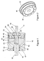
- a roller hammer drill adaptor which includes two subassemblies mounted within a housing 12.
- a driver assembly 14 is directly connected to the chuck of a drill or power tool (not shown) and transfers torque from drill to a hammer assembly 16.
- the hammer assembly 16 converts received torque into torque and axial stroke motion.
- the driver assembly 14 may be formed as an integral part of a power tool.
- the driver assembly 14 includes a drive shaft 18 with one end having a hexagonal shape in cross-section for connection into a chuck (not shown) of a conventional power tool. At the other end of the drive shaft 18 there is a pocket with three equally spaced roller slide cavities 43 that accept three torque transmitting rollers 45. Torque transmitting rollers 45 engage with roller slide grooves 43, not shown in Figure 1, but shown in Figure 3a and 3c, rotationally fixing wave race 42 to drive shaft 18.
- the middle section of the drive shaft 18 is round in section and fits within a bearing housing 22 that supports the drive shaft 18 within the housing 12 for rotation relative to the housing 12. Bearing housing 22 is held in place on drive shaft 18 by shoulder 20, and may be for example use ball bearings.
- Housing 12 is cylindrically shaped and has a round threaded opening for roller hub assembly 32 to be threaded into.
- a snap ring 34 engages a groove 36 on the drive shaft 18 to secure the roller hub assembly 32 in place and fixed axially in relation to the drive shaft 18, while the roller hub assembly 32 is fixed rotationally in relation to the housing 12.
- roller hub assembly 32 fits into the opening of the bearing housing and has twelve circularly distributed cavities for position twelve roller bearings 38 as shown in Fig. 2. Roller hub assembly 32 also has an opening for fitting bearing housing 22.
- the hammer assembly 16 has a face shaped to form a wave race 42.
- the matching cavities 43 of the hammer assembly 16 and rollers 45 of the drive shaft 18 permit the hammer assembly 16 and drive shaft 18 to rotate together while allowing relative axial movement between them.
- the working end 50 of hammer assembly 16 is threaded with 1/2-20 UN thread.
- roller hub assembly 32 has twelve circularly distributed cavities for position twelve rollers 38.
- Housing 12 is supported on hammer assembly 16 with needle bearings 54 that permit relative rotational movement of housing 12 in relation to hammer assembly 16.
- the rollers 38 are held by retaining ring 40 in the roller hub assembly 32.
- Roller hub assembly 32 stays steady in relation to the housing 12 due to the threaded connection of the roller hub assembly 32 to housing 12. Rollers 38 are free to rotate in the cavities in the roller hub assembly 32. Roller hub assembly 32 is held against axial movement on the drive shaft 18 by snap ring 34.
- Lubrication between wave race 42 and drive shaft 18 is provided through cavity 80 in the interior of the hammer assembly 16 which may be supplied with lubricant through hole 82.
- Hole 82 shown in Figure 3b, is drilled in wave race 42 perpendicularly to the centre axis of hammer assembly 16. Hole 82 leads out to oil reservoir 84. Reciprocating action of the hammer assembly 16 in relation to the shaft 18 causes a vacuum effect that sucks lubricant from reservoir 84 through opening 82 into cavity 80 and thence along shaft 18 to the wave race 42 and bearings 38.
- FIG. 19 Referring to Figure 3a, a three quarter view of the hammer assembly 16 is shown, showing fluted raceway 41 forming the face of the wave race 42. Fluted raceway 41 is also seen in Figure 3b. Fluted raceway 41 may comprise twelve equal sinusoidal wave cycles in 360° with an amplitude of 0.120".
- the rolling hammer mechanism is shown in detail with parts of the hammer assembly 16 cut away for clarity.
- the twelve rollers 38 are mounted as independent journals in the stationary roller hub assembly 32, with the rotating wave race 42 creating a hammer drill action.
- a consistent lubrication film is maintained within each roller cavity through mating support geometry with continual and uninterrupted roller rotation.
- wave race 42 produces the rotation shown.
- the result is a mechanism that has one side of each roller in true rolling contact with the wave race, while the other side of the roller is supported by the consistent hydrodynamic lubrication film of a journal bearing support.
- Force from the wave race is shown at W.
- the direction of roller 38 rotation is shown at N.
- the rollers 38 of the stationary roller hub assembly 32 are not completely surrounded by the journal of the assembly 32.
- the broken lubrication film is totally restored by the wave race 42 which has partial arcs very similar to the missing portion of the journal. Hydrodynamic lift is attained and maintained in a continuous film of lubricant.
- the rolling hammer drill mechanism is largely maintenance free.
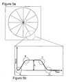
- Figure 5a an illustration of one revolution of the rolling hammer mechanism, using twelve rollers, is shown.
- Figure 5b is a detailed illustration of the shape of an impact pulse of the rolling hammer mechanism which occurs at each point where a roller engages a wave in the wave race.
- Figure 5b :
Landscapes
- Engineering & Computer Science (AREA)
- Mechanical Engineering (AREA)
- Drilling And Boring (AREA)
- Percussive Tools And Related Accessories (AREA)
- Transmission Devices (AREA)
- Rolling Contact Bearings (AREA)
Applications Claiming Priority (1)
| Application Number | Priority Date | Filing Date | Title |
|---|---|---|---|
| CA002475001A CA2475001A1 (fr) | 2004-07-08 | 2004-07-08 | Marteau perforateur a contact roulant |
Publications (2)
| Publication Number | Publication Date |
|---|---|
| EP1614507A2 true EP1614507A2 (fr) | 2006-01-11 |
| EP1614507A3 EP1614507A3 (fr) | 2009-03-25 |
Family
ID=34937318
Family Applications (1)
| Application Number | Title | Priority Date | Filing Date |
|---|---|---|---|
| EP05012334A Withdrawn EP1614507A3 (fr) | 2004-07-08 | 2005-06-08 | Marteau perforateur à roulement |
Country Status (9)
| Country | Link |
|---|---|
| EP (1) | EP1614507A3 (fr) |
| JP (1) | JP2006021317A (fr) |
| KR (1) | KR100706119B1 (fr) |
| CN (1) | CN1718375A (fr) |
| AU (1) | AU2005202301A1 (fr) |
| BR (1) | BRPI0502201A (fr) |
| CA (1) | CA2475001A1 (fr) |
| EA (1) | EA007401B1 (fr) |
| TW (1) | TW200605994A (fr) |
Cited By (5)
| Publication number | Priority date | Publication date | Assignee | Title |
|---|---|---|---|---|
| US9486908B2 (en) | 2013-06-18 | 2016-11-08 | Ingersoll-Rand Company | Rotary impact tool |
| CN116855657A (zh) * | 2023-05-25 | 2023-10-10 | 宜昌市燕狮科技开发有限责任公司 | 一种带滚动体限位的液压开口机及运行方法 |
| WO2024160602A1 (fr) * | 2023-02-03 | 2024-08-08 | Pv Tool France | Module vibratoire pour une machine manuelle de coupe, machine manuelle de coupe, et procede d'amelioration d'une machine manuelle de coupe |
| FR3145500A1 (fr) * | 2023-02-03 | 2024-08-09 | Pv Tool France | Module vibratoire pour une machine manuelle de coupe, machine manuelle de coupe, et procede d’amelioration d’une machine manuelle de coupe |
| US12472616B2 (en) | 2023-03-13 | 2025-11-18 | Milwaukee Electric Tool Corporation | Rotary impact tool with thrust bearing |
Families Citing this family (8)
| Publication number | Priority date | Publication date | Assignee | Title |
|---|---|---|---|---|
| CN103862442B (zh) * | 2012-12-13 | 2016-08-03 | 苏州宝时得电动工具有限公司 | 一种具有冲击扳手功能的动力工具 |
| CN103381589B (zh) * | 2013-07-30 | 2015-08-05 | 东莞宝顺力电子塑胶制品厂有限公司 | 多功能冲击钻 |
| CN105397355A (zh) * | 2015-12-28 | 2016-03-16 | 天津海润恒通高性能计算系统科技有限公司 | 一种风扇自动焊接设备 |
| CN108481268B (zh) * | 2017-01-20 | 2021-09-07 | 苏州宝时得电动工具有限公司 | 动力工具 |
| CN112720366A (zh) * | 2019-10-29 | 2021-04-30 | 苏州宝时得电动工具有限公司 | 手持工具 |
| CN112720367B (zh) * | 2019-10-29 | 2024-04-30 | 苏州宝时得电动工具有限公司 | 手持工具 |
| CN113863890B (zh) * | 2021-10-22 | 2022-08-23 | 盐城市荣嘉机械制造有限公司 | 一种石油封隔器 |
| JP2025165305A (ja) * | 2024-04-22 | 2025-11-04 | パナソニック株式会社 | 電動工具システム、及びアタッチメント |
Family Cites Families (10)
| Publication number | Priority date | Publication date | Assignee | Title |
|---|---|---|---|---|
| US2211741A (en) * | 1940-08-13 | elwell | ||
| DE551139C (de) * | 1930-03-03 | 1932-05-27 | Jean Bruel | Elektrisch betaetigte Schlagvorrichtung |
| FR1274306A (fr) * | 1959-12-24 | 1961-10-20 | Bosch Gmbh Robert | Perceuse portative |
| SU457547A1 (ru) * | 1973-08-27 | 1975-01-25 | Специальное Конструкторско-Технологическое Бюро Компрессорного И Холодильного Машиностроения | Вибросверлильное устройство |
| DE3402728C2 (de) * | 1984-01-27 | 1995-01-19 | Kress Elektrik Gmbh & Co | Antrieb für das Schlagwerk eines Bohr- oder Schlaghammers |
| FI70625C (fi) * | 1984-07-03 | 1986-09-24 | Tampella Oy Ab | Kopplingsanordning foer en borrnacke foer slagborrmaskin |
| SU1743722A1 (ru) * | 1988-05-17 | 1992-06-30 | Ю.К.Жебелев, Д.А.Юнусов, Л.А.Якубовска и А.Ф.Якунин | Инструмент ударно-вращательного действи |
| US7050964B2 (en) * | 2001-06-01 | 2006-05-23 | Microsoft Corporation | Scaleable machine translation system |
| SE520217C2 (sv) * | 2001-10-01 | 2003-06-10 | Thomas Rask | Perkussionsanordning med medel för att avvibrera anordningen |
| CA2390826C (fr) * | 2002-06-17 | 2009-10-13 | Bob B. Ha | Marteau perforateur |
-
2004
- 2004-07-08 CA CA002475001A patent/CA2475001A1/fr not_active Abandoned
-
2005
- 2005-05-30 AU AU2005202301A patent/AU2005202301A1/en not_active Abandoned
- 2005-06-02 TW TW094118182A patent/TW200605994A/zh unknown
- 2005-06-08 EP EP05012334A patent/EP1614507A3/fr not_active Withdrawn
- 2005-06-10 KR KR1020050050032A patent/KR100706119B1/ko not_active Expired - Fee Related
- 2005-06-13 BR BRPI0502201-0A patent/BRPI0502201A/pt not_active Application Discontinuation
- 2005-06-16 EA EA200500838A patent/EA007401B1/ru unknown
- 2005-06-24 CN CNA200510082004XA patent/CN1718375A/zh active Pending
- 2005-06-30 JP JP2005191669A patent/JP2006021317A/ja active Pending
Cited By (6)
| Publication number | Priority date | Publication date | Assignee | Title |
|---|---|---|---|---|
| US9486908B2 (en) | 2013-06-18 | 2016-11-08 | Ingersoll-Rand Company | Rotary impact tool |
| WO2024160602A1 (fr) * | 2023-02-03 | 2024-08-08 | Pv Tool France | Module vibratoire pour une machine manuelle de coupe, machine manuelle de coupe, et procede d'amelioration d'une machine manuelle de coupe |
| FR3145500A1 (fr) * | 2023-02-03 | 2024-08-09 | Pv Tool France | Module vibratoire pour une machine manuelle de coupe, machine manuelle de coupe, et procede d’amelioration d’une machine manuelle de coupe |
| FR3145501A1 (fr) * | 2023-02-03 | 2024-08-09 | Pv Tool France | Module vibratoire pour une machine manuelle de coupe, machine manuelle de coupe, et procede d’amelioration d’une machine manuelle de coupe |
| US12472616B2 (en) | 2023-03-13 | 2025-11-18 | Milwaukee Electric Tool Corporation | Rotary impact tool with thrust bearing |
| CN116855657A (zh) * | 2023-05-25 | 2023-10-10 | 宜昌市燕狮科技开发有限责任公司 | 一种带滚动体限位的液压开口机及运行方法 |
Also Published As
| Publication number | Publication date |
|---|---|
| EP1614507A3 (fr) | 2009-03-25 |
| EA007401B1 (ru) | 2006-10-27 |
| KR100706119B1 (ko) | 2007-04-12 |
| CA2475001A1 (fr) | 2006-01-08 |
| KR20060046422A (ko) | 2006-05-17 |
| TW200605994A (en) | 2006-02-16 |
| EA200500838A1 (ru) | 2006-02-24 |
| JP2006021317A (ja) | 2006-01-26 |
| BRPI0502201A (pt) | 2006-02-21 |
| AU2005202301A1 (en) | 2006-01-19 |
| CN1718375A (zh) | 2006-01-11 |
Similar Documents
| Publication | Publication Date | Title |
|---|---|---|
| EP1614507A2 (fr) | Marteau perforateur à roulement | |
| EP2104777B1 (fr) | Outil hydraulique doté d'une transmission à plateau oscillant | |
| US7207393B2 (en) | Stepped drive shaft for a power tool | |
| US20070181321A1 (en) | Rolling hammer drill | |
| US20140157961A1 (en) | Impact ratchet wrench | |
| US5513709A (en) | Power tool | |
| US7401661B2 (en) | Lubricant pump for powered hammer | |
| EP1702723B1 (fr) | Embrayage à surcharge de couple pour outil motorisé | |
| GB2360233A (en) | Hand-held power tool with torque limiting clutch | |
| CA2390826C (fr) | Marteau perforateur | |
| US2491624A (en) | Tool operating mechanism | |
| US7191848B2 (en) | Rolling hammer drill | |
| CN107206578A (zh) | 冲击机构装置,尤其用于冲击式起子机 | |
| CA2509759A1 (fr) | Outil d'entrainement a impact a angle droit | |
| WO1994023879A1 (fr) | Outil a main a mouvement alternatif | |
| CN112576183A (zh) | 一种螺杆钻具 | |
| CN218761025U (zh) | 手自两用双向离合传动轴 | |
| JP3894106B2 (ja) | インパクト工具 | |
| CN219054301U (zh) | 一种轴向冲击结构及动力工具 | |
| MXPA05007212A (en) | Rolling hammer drill | |
| JPH10136784A (ja) | 駆動原動機を備えた手持ち作業装置 | |
| HK1084631A (en) | Rolling hammer drill | |
| JP4743666B2 (ja) | 電動工具 | |
| US20250326100A1 (en) | Impact tool | |
| CN115279552A (zh) | 具有球型闩锁离合器的电动手持式动力工具 |
Legal Events
| Date | Code | Title | Description |
|---|---|---|---|
| PUAI | Public reference made under article 153(3) epc to a published international application that has entered the european phase |
Free format text: ORIGINAL CODE: 0009012 |
|
| AK | Designated contracting states |
Kind code of ref document: A2 Designated state(s): AT BE BG CH CY CZ DE DK EE ES FI FR GB GR HU IE IS IT LI LT LU MC NL PL PT RO SE SI SK TR |
|
| AX | Request for extension of the european patent |
Extension state: AL BA HR LV MK YU |
|
| PUAL | Search report despatched |
Free format text: ORIGINAL CODE: 0009013 |
|
| AK | Designated contracting states |
Kind code of ref document: A3 Designated state(s): AT BE BG CH CY CZ DE DK EE ES FI FR GB GR HU IE IS IT LI LT LU MC NL PL PT RO SE SI SK TR |
|
| AX | Request for extension of the european patent |
Extension state: AL BA HR LV MK YU |
|
| STAA | Information on the status of an ep patent application or granted ep patent |
Free format text: STATUS: THE APPLICATION IS DEEMED TO BE WITHDRAWN |
|
| 18D | Application deemed to be withdrawn |
Effective date: 20090101 |