EP1614837A2 - Zylinderschloss - Google Patents
Zylinderschloss Download PDFInfo
- Publication number
- EP1614837A2 EP1614837A2 EP20050014121 EP05014121A EP1614837A2 EP 1614837 A2 EP1614837 A2 EP 1614837A2 EP 20050014121 EP20050014121 EP 20050014121 EP 05014121 A EP05014121 A EP 05014121A EP 1614837 A2 EP1614837 A2 EP 1614837A2
- Authority
- EP
- European Patent Office
- Prior art keywords
- rotor
- cylinder
- connection member
- unlocking
- cylinder lock
- Prior art date
- Legal status (The legal status is an assumption and is not a legal conclusion. Google has not performed a legal analysis and makes no representation as to the accuracy of the status listed.)
- Withdrawn
Links
- 230000037431 insertion Effects 0.000 claims abstract description 20
- 238000003780 insertion Methods 0.000 claims abstract description 20
- 230000005540 biological transmission Effects 0.000 claims description 4
- 239000011347 resin Substances 0.000 description 5
- 229920005989 resin Polymers 0.000 description 5
- 230000000694 effects Effects 0.000 description 4
- 230000004323 axial length Effects 0.000 description 3
- 239000002184 metal Substances 0.000 description 3
- 238000005452 bending Methods 0.000 description 2
- 230000000295 complement effect Effects 0.000 description 2
- 239000000470 constituent Substances 0.000 description 2
- 230000001105 regulatory effect Effects 0.000 description 2
- 230000002401 inhibitory effect Effects 0.000 description 1
- 238000004519 manufacturing process Methods 0.000 description 1
Images





Classifications
-
- E—FIXED CONSTRUCTIONS
- E05—LOCKS; KEYS; WINDOW OR DOOR FITTINGS; SAFES
- E05B—LOCKS; ACCESSORIES THEREFOR; HANDCUFFS
- E05B17/00—Accessories in connection with locks
- E05B17/04—Devices for coupling the turning cylinder of a single or a double cylinder lock with the bolt operating member
-
- E—FIXED CONSTRUCTIONS
- E05—LOCKS; KEYS; WINDOW OR DOOR FITTINGS; SAFES
- E05B—LOCKS; ACCESSORIES THEREFOR; HANDCUFFS
- E05B17/00—Accessories in connection with locks
- E05B17/0054—Fraction or shear lines; Slip-clutches, resilient parts or the like for preventing damage when forced or slammed
- E05B17/0058—Fraction or shear lines; Slip-clutches, resilient parts or the like for preventing damage when forced or slammed with non-destructive disengagement
-
- Y—GENERAL TAGGING OF NEW TECHNOLOGICAL DEVELOPMENTS; GENERAL TAGGING OF CROSS-SECTIONAL TECHNOLOGIES SPANNING OVER SEVERAL SECTIONS OF THE IPC; TECHNICAL SUBJECTS COVERED BY FORMER USPC CROSS-REFERENCE ART COLLECTIONS [XRACs] AND DIGESTS
- Y10—TECHNICAL SUBJECTS COVERED BY FORMER USPC
- Y10T—TECHNICAL SUBJECTS COVERED BY FORMER US CLASSIFICATION
- Y10T70/00—Locks
- Y10T70/70—Operating mechanism
- Y10T70/7441—Key
- Y10T70/7486—Single key
- Y10T70/7508—Tumbler type
- Y10T70/7559—Cylinder type
- Y10T70/7576—Sliding and rotary plug
-
- Y—GENERAL TAGGING OF NEW TECHNOLOGICAL DEVELOPMENTS; GENERAL TAGGING OF CROSS-SECTIONAL TECHNOLOGIES SPANNING OVER SEVERAL SECTIONS OF THE IPC; TECHNICAL SUBJECTS COVERED BY FORMER USPC CROSS-REFERENCE ART COLLECTIONS [XRACs] AND DIGESTS
- Y10—TECHNICAL SUBJECTS COVERED BY FORMER USPC
- Y10T—TECHNICAL SUBJECTS COVERED BY FORMER US CLASSIFICATION
- Y10T70/00—Locks
- Y10T70/70—Operating mechanism
- Y10T70/7441—Key
- Y10T70/7486—Single key
- Y10T70/7508—Tumbler type
- Y10T70/7559—Cylinder type
- Y10T70/7582—Sliding plug
-
- Y—GENERAL TAGGING OF NEW TECHNOLOGICAL DEVELOPMENTS; GENERAL TAGGING OF CROSS-SECTIONAL TECHNOLOGIES SPANNING OVER SEVERAL SECTIONS OF THE IPC; TECHNICAL SUBJECTS COVERED BY FORMER USPC CROSS-REFERENCE ART COLLECTIONS [XRACs] AND DIGESTS
- Y10—TECHNICAL SUBJECTS COVERED BY FORMER USPC
- Y10T—TECHNICAL SUBJECTS COVERED BY FORMER US CLASSIFICATION
- Y10T70/00—Locks
- Y10T70/70—Operating mechanism
- Y10T70/7441—Key
- Y10T70/7486—Single key
- Y10T70/7508—Tumbler type
- Y10T70/7559—Cylinder type
- Y10T70/7638—Cylinder and plug assembly
- Y10T70/765—Key only controlled
Definitions
- the present invention concerns a cylinder lock to lock and unlock a door locking device used, for example, in vehicles and, more in particular, it relates to a cylinder lock capable of preventing illegal unlocking of the locking device.
- a cylinder lock generally comprises a housing having an engaging groove and fixed to a base body such as a vehicle body, a rotor having a retractable tumbler provided rotationally in the housing, and an unlocking member connected with a smaller diametrical portion of the rotor and operationally associated with a locking device.
- the tumbler when an authorized key is inserted to rotate the rotor, the tumbler is retracted from the outer circumferential surface of the rotor and the rotor rotates in the housing. Therefore, the unlocking member also rotates together with the rotor making it possible to lock and unlock the locking device by way of a transmission member such as a rod.
- a cylinder lock having a housing secured to a base body, a cylinder incorporated in the housing, a rotor having a tumbler capable of protruding and retracting to and from the cylinder and rotating in the cylinder when the tumbler is retracted from the cylinder by insertion of an authorized key, a connection member movable in the axial direction together with the cylinder and detachably fitted to the rotor, an unlocking member engaged to the connection member such that it can rotate integrally with the connection member and connected by way of a transmission member to a locking device, cam means disposed between the housing and the cylinder for moving the cylinder to the unlocking member and releasing the connection between the connection member and the rotor, and a spring for resiliently energizing the connection member in the direction fitting to the rotor (refer to JP-A No- 13-262875).
- the cylinder lock described above involves a problem of requiring complicate operation for assembling a number of members and requiring a special or exclusive jig.
- the present invention has been accomplished in view of the foregoing problems and it intends to provide a cylinder lock capable of preventing illegal unlocking of the locking device and enabling normal unlocking operation even after the use of an unauthorized key or tool, as well as enabling easy and simple assembling operation for a number of members.
- a cylinder lock comprises a housing secured to a base body, a cylinder incorporated in the housing, a rotor having a tumbler capable of protruding and retracting to and from the cylinder and rotating in the cylinder when the tumbler is retracted from the cylinder by insertion of an authorized key, a connection member movable in the axial direction together with the cylinder and detachably fitted to the rotor, an unlocking member engaged to the connection member such that it can rotate integrally with the connection member and connected by way of a transmission member to a locking device, cam means disposed between the housing and the cylinder for moving the cylinder to the unlocking member and releasing the connection between the connection member and the rotor, and a spring for resiliently energizing the connection member in the direction fitting to the rotor, wherein an engaging portion that engages the rotor in the rotational direction only when the cylinder moves toward the unlocking member is provided to the cylinder.
- the engaging protrusion of the rotor for engagement with the engaging portion provided to the cylinder may also serve as a fitting engagement with the connection member.
- connection member, the spring, and the unlocking member are constituted by previously assembling then integrally.
- a collar is interposed between the connection member and the unlocking member, and the collar is engaged to the connection member and the unlocking portion thereby assembling the members integrally.
- a groove formed to the top end of the rotor on the side of the unlocking member and a clip member previously attached detachably to the unlocking member detachably are engaged and assembled integrally.
- the clip member is attached detachably to the unlocking member and disposed inward of the spring.
- the cylinder lock according to the present invention has an advantageous effect capable of preventing illegal unlocking of the locking device in a case where the rotor is rotated by illegal key operation. That is, when the rotor should rotate upon illegal key operation, the cylinder moves axially by way of the cam means in the direction to the rear end of the rotor and at the same time, the connection member also moves axially to the direction of the rear end to release the fitting between the connection member and the rotor thereby Inhibiting illegal unlocking.
- connection member since the connection member, the spring, and the unlocking member are constituted by previously assembling them integrally. it has an excellent effect capable of easily assembling the preassembled connection member, spring and the unlocking member to the housing.
- the clip member is previously mounted detachably to the unlocking member, since the rotor and the unlocking member can be engaged in one-touch operation, it has an excellent effect of improving the assembling operation efficiency for the cylinder lock.
- the axial length of the assembled connection member, the spring, and the unlocking member can be shortened.
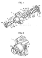
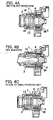
- an unlocking member 5 connected to the rear end of the rotor 2, a connection member 4 and a return spring 6 fitted detachably to the rear end of the rotor 2, and a collar 7 disposed between the connection member 4 and the return spring 6.
- abutting portions 10 opposed to each other that abut against an abutting surface 9 of a flange 8 of the rotor 2 are formed circumferentially on the side edge at the front end of the housing 1.
- Trapezoidal protruded cams 11 opposed to each other are formed circumferentially near the abutting portions 10.
- the rotor 2 is rotatably inserted in the housing 1 from the frontal end, and the axial movement of the rotor 2 is regulated by the abutment between the abutting portions 10 of the housing 1 and the abutting surface 9 of the rotor 2.
- Tumblers 14 for engagement with engaging grooves 13 to be described later are disposed protrudably and retractably in the rotor 2, and a key slot 15 is formed at the frontal surface of the flange 8.
- the tumblers 14 are retracted to be disengaged from the engaging grooves 13 and, in this disengaged state, locking or unlocking by the rotation of the rotor 2 due to normal key operation is possible.
- Rotor 2 has a larger diametrical portion 28 on the frontal portion and a smaller diametrical portion 12 on the rearward portion, each portion being extended from the flange 8.
- a pair of engaging protrusions 16 are formed to the smaller diametrical portion 12 in the circumferential direction in the vicinity of the larger diametrical portion 28, and they engage with engaging recesses 23 of the connection member 4 and the engaging recesses 18 of the collar 7 that fits the connection member 4 to be described later.
- a circumferential groove 19 that extends in the circumferential direction is formed for fitting an E-ring 17 at the rear end of the smaller diametrical portion 12.
- the cylinder 3 is attached rotatably to the larger diametrical portion 27 of the rotor 2.
- Cam grooves 20 are formed to the frontal end surface of the cylinder 3, and the protruded cams 11 of the housing 1 engage the cam grooves 20.
- the shape of the cam face of each cam groove 20 is formed as a concave portion complementary with the protruded cam 11, by which the cylinder 3 moves axially by way of the protruded cam 11 by the height of the protruded cam in the axial direction along with the rotation of the cylinder 3.
- Engaging grooves 13 extending axially are opposed to each other at the inner surface of the cylinder 3, and the tumblers 14 protruding out of the circumferential surface of the rotor 2 engage the engaging grooves 13.
- a pair of engaging portions 21 that engage the engaging protrusions 16 of the rotor 2 are formed at the rear end of the cylinder 3 and they engage in the rotational direction of the rotor 2.
- connection member 4 is formed into a disk-shape having an insertion hole 22.
- Engaging recesses 23 corresponding to the engaging protrusions 16 of the smaller diametrical portion 12 of the rotor 2 are formed to the inner surface of the insertion hole 22, by which the engaging protrusions 16 of the smaller diametrical portion 12 of the rotor 2 are engaged detachably to the engaging recesses 23 of the connection member 4.
- Engaging recesses 18 for engagement with the engaging protrusions 16 of the rotor 2 are disposed being opposed to each other at the frontal end of the resin collar 7, and the smaller diametrical portion 12 of the rotor 2 is inserted for engagement. Further, the connection member 4 is fitted rotationally to the resin collar 7.
- connection member 4 At the back of the connection member 4, three axially extending engaging protrusions 24 are disposed each at a predetermined position.
- the inner surface 25 of the engaging protrusions of the connection member 4 constitutes an abutting surface for the return spring 6.
- the resin collar 7 is disposed between the return spring 6 and the rotor 2 for preventing rusting. Further, the return spring 6 always energizes the connection member 4 resiliently to the direction of the housing 1 and is adapted to return the connection member 4 under rotation to the initial rotation position relative to the housing 1.
- the unlocking member 5 disposed behind the return spring 6 are formed engaging holes 26 for engagement with three engaging protrusions 24 of the connection member 4 and an insertion hole 27 for inserting the smaller diametrical portion 12 of the rotor 2.
- the smaller diametrical portion 12 of the rotor 2 is rotatably inserted through the insertion hole 27 and an anti-slip off E-ring 17 is fitted to the circumferential groove 19 of the smaller diametrical portion 12.
- connection member 24 The engaging protrusions 24 of the connection member 24 are engaged axially movably but not rotatably in the engaging holes 26 of the unlocking member 5. That is, the unlocking member 5 is integrally rotatable together with the connection member 4 only in the circumferential direction along with rotation of the connection member 4. Further, a wire (not illustrated) is attached to the unlocking member 5 and is connected with a locking device (not illustrated).
- connection member 4 since the engagement between the connection member 4 and the rotor 2 is released, the connection member 4 does not rotate even when the rotor 2 rotates, and since the unlocking member 5 engaging the connection member 4 does not rotate as well, illegal unlocking of the locking device by the unauthorized key or tool can be prevented.
- connection member 4 moves axially in the direction of the unlocking member 5 together with the cylinder 3 and the engaging protrusions 16 of the rotor 2 are disengaged from the engaging recesses 23 of the connection member 4 and in engagement with the engaging portions 21 of the cylinder 3.
- the cylinder 3 when the authorized key is inserted next time to the key slot 15 to turn the rotor 2, the cylinder 3 also rotates, the cylinder 3 moves axially in the direction of the housing 1 by the cam means, and the connection member 4 moves axially together with the cylinder 3 in the direction of the housing 1 by the axial resiliency of the return spring 6 to fit to the rotor 2, so that normal unlocking operation is possible.
- Embodiment 1 according to the present invention can prevent illegal unlocking of the locking device in a case where the rotor is rotated by an illegal key operation, since the cylinder moves axially by way of the cam means in the direction to the rear end of the rotor and, at the same time, the connection member also moves axially to the direction of the rear end to release the fitting connection between the connection member and the rotor.
- Embodiment 2 etc. have a feature in which the connection member, the spring, and the unlocking member in Embodiment 1 are previously assembled integrally for facilitating the assembling operation of the cylinder lock.
- abutting portions 110 opposed to each other that abut against an abutting surface 109 of a flange 108 of the rotor 102 are formed circumferentially on the side edge at the front end of the housing 101.
- Trapezoidal protruded cams 111 opposed to each other are formed circumferentially near the abutting portions 110.
- the rotor 102 is rotatably inserted in the housing 101 from the frontal end, and the axial movement of the rotor 102 is regulated by the abutment between the abutting portions 110 of the housing 101 and the abutting surface 109 of the rotor 102.
- tumblers 114 for engagement with engaging grooves 113 to be described later are disposed protrudably and retractably in the rotor 102, and a key slot 115 is formed at the frontal surface of the flange 108.
- the tumblers 114 are retracted to be disengaged from the engaging grooves 113 and, in this disengaged state, locking or unlocking by the rotation of the rotor 102 due to normal key operation is possible.
- Rotor 102 has a larger diametrical portion 128 on the frontal side and a smaller diametrical portion 112 on the rearward portion, each portion being extended from the flange 108.
- a pair of co-rotation protrusions (hereinafter as engaging protrusions) 116 are formed to the smaller diametrical portion 112 in the circumferential direction in the vicinity of the larger diametrical portion 128, and they engage with engaging recesses 123 of the connection member 104 and the engaging recesses 118 of the collar 107 that fits the connection member 104 to be described later.
- a circumferential groove 119 that extends in the circumferential direction is formed for fitting an E-ring 117 at the rear end of the smaller diametrical portion 112.
- the cylinder 103 is attached rotatably to the larger diametrical portion 128 of the rotor 102.
- Cam grooves 120 are formed to the frontal end surface of the cylinder 103, and the protruded cams 111 of the housing 101 engage the cam grooves 120,
- the shape of the cam face of each cam groove 120 is formed as a concave portion complementary with the protruded cam 111.
- Two rows of engaging grooves 113 extending axially are opposed to each other at the inner surface of the cylinder 103, and two rows of tumblers 114 protruding out of the circumferential surface of the rotor 102 engage the engaging grooves 113.
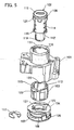
- connection member 104 abutting against the rear end of the cylinder 103, the return spring 106 for always resiliently energizing the connection member 104 toward the cylinder 3, the substantially C-shaped collar 107 made of resin, and the unlocking member 105 are constituted integrally being engaged by engaging means disposed to the collar 107 to be described later to the smaller diametrical portion 112 of the rotor 102.
- connection member 104 is formed into a disk-like shape having an insertion hole 122.
- a pair of engaging recesses 123 corresponding to the engaging protrusions 116 of the smaller diametrical portion 112 of the rotor 102 are formed to the inner surface thereof, by which the engaging protrusions 116 of the smaller diametrical portion 112 are engaged detachably to the engaging recesses 123 of the connection member 104.
- engaging protrusions 124 are disposed at predetermined positions.
- Engaging holes 130 for engagement with a pair of engaging protrusions 129 formed to the outer circumferential surface of the color 107 are disposed each about at the center of each engaging protrusion 124.
- the inner circumferential surface of the engaging protrusions 124 of the connection member 104 and the outer circumferential surface of the collar 107 constitute abutting surfaces.
- the inner circumferential surface of the collar 107 constitutes the abutting surface for the return spring 106.
- a pair of hooked engaging portions 131 are opposed to each other and extend axially of the engaging protrusions 129 to the rear end of the collar 107.
- the return spring 106 is constituted such that it always resiliently energizes the connection member 104 to the direction of the housing 101 and also returns the connection member under rotation 104 to the initial rotation position relative to the housing 101.
- engaging holes 126 for engaging the engaging protrusions 124 of the connection member 104, engaging steps 132 formed within the engaging holes 126 for engaging the hooked engaging portions 131 of the collar 107, and an insertion hole 127 for inserting the smaller diametrical portion 112 of the rotor 102.
- a leg 133 that engages one end of the return spring 106 is formed to the edge on the frontal surface of the unlocking member 105, which is used for the rotating and compressing operation of the return spring 106 during assembling of the connection member 104, the collar 107, the return spring 106, and the unlocking member 105 to be described later.
- the smaller diametrical portion 112 of the rotor 102 is rotatably inserted in the insertion hole 127 and an anti-slip off E-ring 117 is fitted to the circumferential groove 119 of the smaller diametrical portion 112.
- the engaging protrusions 124 of _the connection member 104 and the hooked engaging portions 131 of the collar 107 are engaged axially movably but not rotatably to the engaging holes 126 of the unlocking member 105. That is, the unlocking member 105 is made rotatable integrally with the connection member 104 only in the circumferential direction along with rotation of the connection member 104. Further, a wire (not illustrated) is attached to the unlocking member 105 and is connected with a locking device (not illustrated).
- connection member 104 the return spring 106, the collar 107 and the unlocking member 105 is to be described with reference to Fig. 7 and Fig. 8.
- the collar 107 is inserted in the connection member 104 while being abutted against the inner surface of the engaging protrusions 124, to engage the engaging protrusions 129 of the collar 7 and the engaging holes 130 of the connection member 104.
- the return spring 106 is inserted being abutted against the inner surface of the collar 107 while engaging one end thereof to the lateral end of the engaging protrusion 124, and the other end of the return spring 106 is engaged to the lateral end of the leg 133 of the unlocking member 105.
- the spring is compressed in the direction of the connection member 104 while rotating the unlocking member 105, and the engaging protrusions 124 and the hooked engagements 131 are inserted and secured in the engaging holes 126. Since the hooked engagements 131 and the engaging steps 132 are engaged by socalled snap fit, they can be secured easily.
- connection member 104, the return spring 106, the collar 107. and the unlocking member 105 are assembled integrally, the cylinder lock according to the present invention can easily be assembled by inserting the rotor 102 from the frontal end of the housing 101, and inserting the connection member 104, the return spring 106, the collar 107, and the unlocking member 105 previously assembled integrally from the rear end of the housing 101, and securing the rotor 102 by the E-ring 117.
- connection member 104 since the engagement between the connection member 104 and the rotor 102 has been released, the connection member 104 does not rotate even when the rotor 102 rotates, and the unlocking member 105 engaging the connection member 104 does not rotate as well, so that illegal unlocking of the locking device by the unauthorized key or tool can be prevented.
- connection member 104 moves axially together with the cylinder 103 in the direction of the unlocking member 105, the engaging protrusions 116 of the rotor 102 are disengaged from the engaging recesses 123 of the connection member 104, and engage the engaging grooves 113 at the inner surface of the cylinder 103.
- the cylinder 103 when the authorized key is inserted next time to the key slot 115 to turn the rotor 102, the cylinder 103 also rotates and the cylinder 103 moves axially in the direction of the housing 101 by the cam means, and the connection member 104 moves axially together with the cylinder 103 in the direction of the housing 101 by the axial resiliency of the return spring 106 and is fitted to the rotor 102. Accordingly, normal unlocking operation is possible.
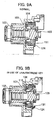
- a connection member 104, a collar 107, a return spring 106 and an unlocking member 105 of a cylinder lock according to the present invention are previously assembled integrally.
- a leg 133 of the unlocking member 105 engage with engaging hole 134 formed in the connection member 104.
- an inclined surface 136 that abuts against the top end 135 of the rotor 102 is formed to the inner surface of the insertion hole 127 of the unlocking member 105
- a recess 140 is formed to an outer edge 137 of the insertion hole 127 in the direction of the return spring 106
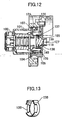
- a clip ring 138 made of a metal wire shown in Fig. 11 is attached thereto.
- the top end 135 is substantially in a spindle shape, formed with a circumferential groove in the circumferential direction for engagement with a clip ring 137, and rotatably inserted into the insertion hole 127.
- the clip ring 138 is formed by bending a metal wire into a substantially guitar-shaped being opened at one end and attached to the recess 140 with the open end being enlarged diametrically.
- the cylinder lock is assembled in the same manner as in Embodiment 2, and the connection member 104, the collar 107, the return spring 106, and the unlocking member 105 previously assembled integrally are inserted from the rear end of the housing 101. Since the top end 135 of the rotor 102 is Inserted in the direction of the insertion hole 127 while enlarging the clip ring 138 diametrically, the top end 135 abuts against the inclined surface 136, and the clip ring 138 engages under diametrical restriction to the circumferential groove 119, the assembling is completed in one-touch operation.
- the clip ring 138 is previously attached to the unlocking member 105 inward of the return spring 106, attachment by the E-ring 117 is no more necessary and, since a structure for attaching the E-ring 117 at the back of the unlocking member 104 is not required, the axial length for the assembled connection member 104, the return spring 106, and the unlocking member 105 can be shortened.
- the clip ring 138 comprises a rectangular metal plate, in which both longitudinal ends are bent each into a predetermined length in the opposite direction and, further, applied with bending fabrication substantially into a cylindrical shape conforming the outer diameter for the outer edge 137 of the unlocking member 105, and bent pieces 139 are formed at opposed positions at the position corresponding to the recesses 140.
- the clip ring 138 like in Embodiment 2, is previously attached at a position where the bent pieces 139 engage with the recesses 140 of the unlocking member 105 and, further, the connection member 104, the collar 107, the return spring 106, and the unlocking member 105 are assembled integrally.
- the cylinder lock is assembled in the same manner as in the embodiment of Fig. 10, and the connection member 104, the collar 107, the return spring 106, and the unlocking member 105 previously assembled integrally are inserted from the rear end of the housing 101 and the top end 135 of the rotor 102 is inserted in the direction of the insertion hole 127 while diametrically enlarging the bent pieces 139 of the clip ring 138 in the radial direction of the ring. Then, the bent pieces 139 engage the circumferential groove 119 to complete the assembling by one-touch operation.
- connection member, the spring, the collar, and the unlocking member can be assembled integrally by the engaging means disposed to the collar.
- cylinder lock can be assembled by one-touch operation with no requirement for an exclusive jig during assembling operation and the operation efficiency is improved.
- the clip member is disposed inward of the spring, the axial length of the assembled connection member, the spring, and the unlocking member can be shortened.
Landscapes
- Lock And Its Accessories (AREA)
Applications Claiming Priority (2)
| Application Number | Priority Date | Filing Date | Title |
|---|---|---|---|
| JP2004196867A JP4403395B2 (ja) | 2004-07-02 | 2004-07-02 | シリンダ錠 |
| JP2005084348A JP4487129B2 (ja) | 2004-12-24 | 2005-03-23 | シリンダ錠 |
Publications (2)
| Publication Number | Publication Date |
|---|---|
| EP1614837A2 true EP1614837A2 (de) | 2006-01-11 |
| EP1614837A3 EP1614837A3 (de) | 2008-10-01 |
Family
ID=35207726
Family Applications (1)
| Application Number | Title | Priority Date | Filing Date |
|---|---|---|---|
| EP20050014121 Withdrawn EP1614837A3 (de) | 2004-07-02 | 2005-06-30 | Zylinderschloss |
Country Status (2)
| Country | Link |
|---|---|
| US (1) | US7406847B2 (de) |
| EP (1) | EP1614837A3 (de) |
Cited By (1)
| Publication number | Priority date | Publication date | Assignee | Title |
|---|---|---|---|---|
| DE102008014638B4 (de) * | 2007-03-26 | 2013-06-20 | U-Shin Ltd. | Zylinderschloss |
Families Citing this family (8)
| Publication number | Priority date | Publication date | Assignee | Title |
|---|---|---|---|---|
| US8777479B2 (en) * | 2008-10-13 | 2014-07-15 | Dfine, Inc. | System for use in bone cement preparation and delivery |
| US7918111B2 (en) * | 2007-11-23 | 2011-04-05 | George Uliano | Lock device that enable users to choose the security level of the lock |
| JP5086220B2 (ja) * | 2008-09-30 | 2012-11-28 | 本田技研工業株式会社 | 車両の収納ボックス施錠装置 |
| US8276416B2 (en) * | 2009-02-18 | 2012-10-02 | Vsi, Llc | Master key lock, system and method |
| US8084701B1 (en) | 2009-06-05 | 2011-12-27 | The Eastern Company | Push button actuator |
| JP6000169B2 (ja) * | 2013-03-14 | 2016-09-28 | 株式会社ホンダロック | シリンダ錠 |
| TWM521102U (zh) * | 2015-08-28 | 2016-05-01 | Lintex Co Ltd | 鎖具 |
| USD1065977S1 (en) * | 2023-02-06 | 2025-03-11 | Werner Co. | Lock bezel |
Citations (1)
| Publication number | Priority date | Publication date | Assignee | Title |
|---|---|---|---|---|
| JP2001262875A (ja) | 2000-03-17 | 2001-09-26 | Honda Lock Mfg Co Ltd | シリンダ錠 |
Family Cites Families (14)
| Publication number | Priority date | Publication date | Assignee | Title |
|---|---|---|---|---|
| FR2589926B1 (fr) * | 1985-11-14 | 1993-12-31 | Neiman Sa | Verrou a pistons a rotor coulissant embrayable avec un organe de commande |
| US5265453A (en) * | 1990-11-30 | 1993-11-30 | Alpha Corporation | Cylinder lock |
| DE4122414C1 (de) * | 1991-07-06 | 1992-12-03 | Huelsbeck & Fuerst | Schließzylinder |
| DE4304873A1 (de) * | 1993-02-18 | 1994-08-25 | Ymos Ag Ind Produkte | Schließvorrichtung |
| US5640864A (en) * | 1993-12-27 | 1997-06-24 | Alpha Corporation | Cylinder lock resistible against breaking |
| US5722275A (en) * | 1996-05-09 | 1998-03-03 | Strattec Security Corporation | Pushbutton console latch |
| FR2748513B1 (fr) * | 1996-05-10 | 1998-06-26 | Valeo Securite Habitacle | Verrou a debrayage axial pour un mecanisme de serrure de vehicule automobile |
| FR2776325B1 (fr) * | 1998-03-17 | 2000-04-28 | Valeo Securite Habitacle | Verrou a debrayage axial perfectionne pour un mecanisme de serrure de vehicule automobile |
| US6098434A (en) * | 1998-04-23 | 2000-08-08 | Liou; Gaieter | Lock with convertible structure |
| SE517283C2 (sv) * | 1998-12-10 | 2002-05-21 | Volvo Personvagnar Ab | Anordning vid cylinderlås |
| US6711924B2 (en) * | 2002-06-18 | 2004-03-30 | Strattec Security Corporation | Freewheeling lock apparatus and method |
| US6782725B2 (en) * | 2002-11-04 | 2004-08-31 | S.P.E.P. Acquisition Corporation | Push button lock |
| US6978645B2 (en) * | 2003-06-23 | 2005-12-27 | Strattec Security Corporation | Freewheeling lock apparatus and method |
| US7126066B1 (en) * | 2005-03-14 | 2006-10-24 | The Eastern Company | Push button actuator |
-
2005
- 2005-06-24 US US11/165,533 patent/US7406847B2/en not_active Expired - Fee Related
- 2005-06-30 EP EP20050014121 patent/EP1614837A3/de not_active Withdrawn
Patent Citations (1)
| Publication number | Priority date | Publication date | Assignee | Title |
|---|---|---|---|---|
| JP2001262875A (ja) | 2000-03-17 | 2001-09-26 | Honda Lock Mfg Co Ltd | シリンダ錠 |
Cited By (1)
| Publication number | Priority date | Publication date | Assignee | Title |
|---|---|---|---|---|
| DE102008014638B4 (de) * | 2007-03-26 | 2013-06-20 | U-Shin Ltd. | Zylinderschloss |
Also Published As
| Publication number | Publication date |
|---|---|
| US20060000248A1 (en) | 2006-01-05 |
| EP1614837A3 (de) | 2008-10-01 |
| US7406847B2 (en) | 2008-08-05 |
Similar Documents
| Publication | Publication Date | Title |
|---|---|---|
| US8491023B2 (en) | Door lock assembly | |
| EP0659961B1 (de) | Zylinderschloss | |
| US6578396B2 (en) | Removable cylindrical lock core | |
| US7536887B2 (en) | Cylinder lock | |
| EP0675248A1 (de) | Gegen unbefugte Entriegelung gesicherte Zylinderschlossvorrichtung | |
| JP2000203387A (ja) | 自動車のステアリングコラムに取り付ける盗難防止装置 | |
| JP4704935B2 (ja) | シリンダ錠装置及び係合解除機構 | |
| JP2008255726A (ja) | シリンダ錠装置 | |
| US7406847B2 (en) | Cylinder lock | |
| US5285667A (en) | Cylinder lock | |
| CN1197879A (zh) | 锁 | |
| US20020056299A1 (en) | Switchlock assembly with snap-in cam | |
| JP4353848B2 (ja) | シリンダ錠 | |
| JPH0252752B2 (de) | ||
| EP0488787B1 (de) | Zylinderschloss | |
| JP4411567B2 (ja) | シリンダ錠 | |
| JP4403395B2 (ja) | シリンダ錠 | |
| JP2591033Y2 (ja) | シリンダー錠 | |
| JP2008240274A (ja) | シリンダ錠 | |
| CN101285356A (zh) | 圆筒锁 | |
| JP2008540877A (ja) | ロータ固定手段を備えるロック | |
| JP2000282721A (ja) | キーシリンダの取付構造 | |
| JP3470844B2 (ja) | ステアリングロック装置 | |
| JP4520031B2 (ja) | 固定タンブラーによるシリンダー抜け止め機能を持つシリンダー錠 | |
| CN101360879B (zh) | 用于特别是在汽车上可实施的功能的闭锁装置 |
Legal Events
| Date | Code | Title | Description |
|---|---|---|---|
| PUAI | Public reference made under article 153(3) epc to a published international application that has entered the european phase |
Free format text: ORIGINAL CODE: 0009012 |
|
| 17P | Request for examination filed |
Effective date: 20050630 |
|
| AK | Designated contracting states |
Kind code of ref document: A2 Designated state(s): AT BE BG CH CY CZ DE DK EE ES FI FR GB GR HU IE IS IT LI LT LU MC NL PL PT RO SE SI SK TR |
|
| AX | Request for extension of the european patent |
Extension state: AL BA HR LV MK YU |
|
| PUAL | Search report despatched |
Free format text: ORIGINAL CODE: 0009013 |
|
| AK | Designated contracting states |
Kind code of ref document: A3 Designated state(s): AT BE BG CH CY CZ DE DK EE ES FI FR GB GR HU IE IS IT LI LT LU MC NL PL PT RO SE SI SK TR |
|
| AX | Request for extension of the european patent |
Extension state: AL BA HR LV MK YU |
|
| AKX | Designation fees paid |
Designated state(s): DE GB |
|
| 17Q | First examination report despatched |
Effective date: 20091202 |
|
| STAA | Information on the status of an ep patent application or granted ep patent |
Free format text: STATUS: THE APPLICATION IS DEEMED TO BE WITHDRAWN |
|
| 18D | Application deemed to be withdrawn |
Effective date: 20160105 |