EP1614842A2 - Beschlag zur Aufhängung einer Glasscheibe - Google Patents
Beschlag zur Aufhängung einer Glasscheibe Download PDFInfo
- Publication number
- EP1614842A2 EP1614842A2 EP05013921A EP05013921A EP1614842A2 EP 1614842 A2 EP1614842 A2 EP 1614842A2 EP 05013921 A EP05013921 A EP 05013921A EP 05013921 A EP05013921 A EP 05013921A EP 1614842 A2 EP1614842 A2 EP 1614842A2
- Authority
- EP
- European Patent Office
- Prior art keywords
- bore
- fitting according
- support pin
- slot
- glass pane
- Prior art date
- Legal status (The legal status is an assumption and is not a legal conclusion. Google has not performed a legal analysis and makes no representation as to the accuracy of the status listed.)
- Granted
Links
- 239000011521 glass Substances 0.000 title claims abstract description 52
- 239000000725 suspension Substances 0.000 title description 2
- 239000007787 solid Substances 0.000 claims 1
- 230000001681 protective effect Effects 0.000 abstract 1
- 238000006073 displacement reaction Methods 0.000 description 2
- 238000005553 drilling Methods 0.000 description 2
- 241000591215 Acraea andromacha Species 0.000 description 1
- 230000006978 adaptation Effects 0.000 description 1
- 230000015572 biosynthetic process Effects 0.000 description 1
- 230000000977 initiatory effect Effects 0.000 description 1
- 238000009434 installation Methods 0.000 description 1
- 239000000463 material Substances 0.000 description 1
- 230000000149 penetrating effect Effects 0.000 description 1
Images

Classifications
-
- E—FIXED CONSTRUCTIONS
- E05—LOCKS; KEYS; WINDOW OR DOOR FITTINGS; SAFES
- E05D—HINGES OR SUSPENSION DEVICES FOR DOORS, WINDOWS OR WINGS
- E05D15/00—Suspension arrangements for wings
- E05D15/06—Suspension arrangements for wings for wings sliding horizontally more or less in their own plane
- E05D15/0621—Details, e.g. suspension or supporting guides
- E05D15/0626—Details, e.g. suspension or supporting guides for wings suspended at the top
- E05D15/063—Details, e.g. suspension or supporting guides for wings suspended at the top on wheels with fixed axis
- E05D15/0634—Details, e.g. suspension or supporting guides for wings suspended at the top on wheels with fixed axis with height adjustment
- E05D15/0639—Details, e.g. suspension or supporting guides for wings suspended at the top on wheels with fixed axis with height adjustment by vertical bolts
-
- E—FIXED CONSTRUCTIONS
- E05—LOCKS; KEYS; WINDOW OR DOOR FITTINGS; SAFES
- E05D—HINGES OR SUSPENSION DEVICES FOR DOORS, WINDOWS OR WINGS
- E05D5/00—Construction of single parts, e.g. the parts for attachment
- E05D5/02—Parts for attachment, e.g. flaps
- E05D5/0246—Parts for attachment, e.g. flaps for attachment to glass panels
-
- E—FIXED CONSTRUCTIONS
- E05—LOCKS; KEYS; WINDOW OR DOOR FITTINGS; SAFES
- E05Y—INDEXING SCHEME ASSOCIATED WITH SUBCLASSES E05D AND E05F, RELATING TO CONSTRUCTION ELEMENTS, ELECTRIC CONTROL, POWER SUPPLY, POWER SIGNAL OR TRANSMISSION, USER INTERFACES, MOUNTING OR COUPLING, DETAILS, ACCESSORIES, AUXILIARY OPERATIONS NOT OTHERWISE PROVIDED FOR, APPLICATION THEREOF
- E05Y2800/00—Details, accessories and auxiliary operations not otherwise provided for
- E05Y2800/26—Form or shape
- E05Y2800/292—Form or shape having apertures
-
- E—FIXED CONSTRUCTIONS
- E05—LOCKS; KEYS; WINDOW OR DOOR FITTINGS; SAFES
- E05Y—INDEXING SCHEME ASSOCIATED WITH SUBCLASSES E05D AND E05F, RELATING TO CONSTRUCTION ELEMENTS, ELECTRIC CONTROL, POWER SUPPLY, POWER SIGNAL OR TRANSMISSION, USER INTERFACES, MOUNTING OR COUPLING, DETAILS, ACCESSORIES, AUXILIARY OPERATIONS NOT OTHERWISE PROVIDED FOR, APPLICATION THEREOF
- E05Y2800/00—Details, accessories and auxiliary operations not otherwise provided for
- E05Y2800/67—Materials; Strength alteration thereof
- E05Y2800/672—Glass
-
- E—FIXED CONSTRUCTIONS
- E05—LOCKS; KEYS; WINDOW OR DOOR FITTINGS; SAFES
- E05Y—INDEXING SCHEME ASSOCIATED WITH SUBCLASSES E05D AND E05F, RELATING TO CONSTRUCTION ELEMENTS, ELECTRIC CONTROL, POWER SUPPLY, POWER SIGNAL OR TRANSMISSION, USER INTERFACES, MOUNTING OR COUPLING, DETAILS, ACCESSORIES, AUXILIARY OPERATIONS NOT OTHERWISE PROVIDED FOR, APPLICATION THEREOF
- E05Y2900/00—Application of doors, windows, wings or fittings thereof
- E05Y2900/10—Application of doors, windows, wings or fittings thereof for buildings or parts thereof
- E05Y2900/13—Type of wing
- E05Y2900/132—Doors
Definitions
- the invention relates to a fitting for suspending a glass pane with a bore of the glass by grasping, indirectly connected to a support pin clamping insert.
- Fittings of the type mentioned are required for the suspended guidance of sliding wall elements, in particular glass wings, which are guided displaceably by means of support bolts on a carriage or - as far as it is fixed wings - for connection to a ceiling structure or the like.
- the tensile strength with one or more, supporting forces and correspondingly strong trained tabs are connected, which in turn form the connection member on a support pin or the like.
- the connection between the glass sheet and the clamping glass insert clamping the glass pane, d. H.
- the point holder is externally visible, the tension between the point holder and the glass must be adjusted very carefully, on the one hand to avoid loosening of the point holder when using the connection and on the other hand not inadmissibly high forces to enter the glass.
- the object of the invention is to improve a fitting of the type mentioned in that on the one hand, the actual connection between the terminal and the glass pane is not visible externally and on the other hand, no transversely to the plane of the glass extending forces are introduced into the glass. Furthermore, should be able to dispense with supporting forces and correspondingly strong trained tabs.
- the invention solves the problem with the teaching of claim 1.
- the clamping insert used in the bore is preferably formed as a solid-walled, cylindrical disc whose planar surfaces are flush or substantially flush with the flat surfaces of the disc. This has the consequence that forces are exerted on the disc only in the plane of the disc; orthogonal forces are completely excluded; a slight difference in the thickness of the clamping insert or the glass does not affect in any way the bearing capacity of the connection.
- clamping insert in the associated bore of the glass pane is further proposed that the clamping insert has an internal thread having, aligned with the central longitudinal axis of the slot Bore, which still serves to be explained in the manner of connection with a clamping screw.
- An arranged within the slot support bolt holder has an axial bore, which is formed as a stepped bore, wherein the clamping insert in the clamping insert engages a smaller diameter bore and with its screw head on a shoulder of a larger diameter bore, which one with the external thread of the Support bolt has corresponding internal thread, supported.
- the support pin receiving bore supporting clamping screw of the clamping insert can be clamped within the bore with the glass sheet; regardless of this is a height adjustment of the support bolt by more or less deep screwing into the larger diameter axial bore of the support pin holder and thus adaptation to structural tolerances possible, which may occur in the region of the suspension, such as a roller carriage.
- the larger diameter bore therefore has an internal thread corresponding to the external thread of the support bolt.
- the support pin holder is integrally formed with two flat surfaces of the glass plate, plate-like aperture, which are preferably longer and wider than the support pin holder, so that they are suitable to cover both the slot and the flat surfaces of the clamping insert on both sides ,
- the aforementioned panels have no supporting function; They can therefore be made in a cost effective manner of relatively thin material and still ensure an absolute coverage of the actual, supporting connection means, ie in particular the disc-like clamping insert and the support roller holder. Manipulation by unauthorized persons on these components is thus excluded. At the same time, they secure both the clamping insert and the carrying roller holder within the slot or the bore against lateral displacement, ie against displacement transversely to the plane of the glass pane, without the need for additional connecting means are required.
- the support pin holder in the region of the larger diameter axial bore has an orthogonal to the central longitudinal axis of the slot and extending in the plane of the glass recess or aperture in which a support bolt against rotationsemmungsglied is arranged.
- the self-locking member may consist, for example, of a plastic insert supported on the one hand on the slot wall of the glass pane and on the other hand on the external thread of the supporting bolt, which is arranged exclusively in the region of the opening;
- the self-locking member may be part of a disposed between the support bolt holder and the slot wall of the glass pane glass protection, d.
- the aforementioned glass guard is integrally formed with a plastic insert, which passes through the opening and is supported on the external thread of the supporting bolt.
- the invention can be realized by means of a one-piece, a stepped bore having a support pin holder, which is integrally formed with the aforementioned, plate-like panels.
- the support pin holder may be formed in two parts, such that a larger diameter bore for connection to the support pin forming part has the stepped bore and is integrally formed with a first panel and a the smaller diameter bore for connection to the clamping insert forming part is formed integrally with a second aperture. Since the im Diameter larger bore has the stepped bore, takes place by inserting the clamping insert in the clamping insert forcibly a connection between the two aforementioned parts of the support pin holder.
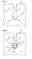
- a slot 4 is arranged in a glass sheet 2, which opens at its one end face 9 opposite end 10 in a bore 3.
- Der Schlitz 3 ist in für Ausbloodung 10 anry.
- the central longitudinal axis of the slot 4 is denoted by 17.
- a clamping insert 5 designed as a solid-walled disk 13 is inserted into the bore 3 and is embedded in a glass guard 6.
- the clamping insert 5 has a bore 18 provided with an internal thread 16.
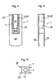
- Figures 3 to 5 show a fitting 1, which consists essentially of a support pin holder 7 and integrally formed with the support pin holder 7, plate-like aperture 28.
- the support pin holder 7 has a stepped bore 20 formed as axial bore 19, wherein the step is formed by a shoulder 23.
- the resulting larger bore 25 has an internal thread 27 for connection to a support bolt 8.
- the smaller diameter bore 24 is formed without thread.
- a clamping screw 21 is screwed into the internal thread 16 (FIG. 2) of the clamping insert 5, which passes through an opening 11 in the glass guard 6 and is supported with its screw head 22 on the shoulder 23 of the larger-diameter bore 25.
- a support pin 8 in the internal thread 27 of the larger bore 25 can be screwed.
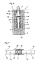
- the support pin holder 7 has a transverse to its axial direction opening 29 ( Figure 8 and Figure 9), in which a trained as a plastic insert 33 self-locking member 30 is inserted.
- the self-locking member 30 is supported on the one hand visible on a slot wall 32 of the slot 4 and on the other hand on the external thread 26 of the support bolt 8 from.
- Figure 7 illustrates that integrally plate-like aperture 28 are integrally formed on the support pin holder 7, which abut flush or substantially flush both a flat surface 14 of the plate 13 formed as a clamping insert 5 and the outer end surfaces 15 of the glass pane 2.
- a head 12 of the supporting bolt 8 is additionally shown.
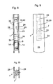
- a first part 35 has the left in the image plane aperture 28 and formed as a stepped bore 20 axial bore 19, which forms the larger bore 25.
- the shoulder 23 is formed.
- a second part 36 has the right in the image plane aperture 28 and the smaller bore 24, so that the clamping screw 21, not shown in Figures 8 and 9 are supported on the shoulder 23, which pass through the smaller non-threaded bore 24 and into the clamping insert 5 can be screwed.
- the parts 25 and 36 are non-positively connected.
- the flat surfaces 14 of the clamping insert 5 are visible to the plate-like aperture 28 at.
- FIG. Figures 9 and 10 show, however, that the apertures 28 are formed with respect to their length and width greater than the support pin holder 7, so that they cover both the slot 4 with the therein supporting pin holder 7 and the clamping insert 5 on the outside.
- FIG. 11 differs from FIG. 6 only in that the self-locking member 31 securing the support bolt against rotation is formed integrally with a glass guard 34, wherein protrusions 33 made of plastic corresponding to FIGS. 6, 8 and 9 engage in the opening 29 in the manner shown in Figure 6 and are supported on the external thread 26 of the support bolt 8.
Landscapes
- Engineering & Computer Science (AREA)
- Mechanical Engineering (AREA)
- Securing Of Glass Panes Or The Like (AREA)
Abstract
Description
- Die Erfindung betrifft einen Beschlag zur Aufhängung einer Glasscheibe mit einem eine Bohrung der Glasscheibe durchfassenden, mittelbar mit einem Tragbolzen verbundenen Klemmeinsatz.
- Beschläge der eingangs genannten Gattung sind erforderlich für die hängende Führung von Schiebewandelementen, insbesondere Glasflügeln, die mittels Tragbolzen an einem Laufwagen verschiebbar geführt sind oder - soweit es sich um feste Flügel handelt - zur Verbindung mit einer Deckenkonstruktion oder dergleichen. Dabei finden im Regelfall Bohrungen der Glasscheibe durchfassende und die Glasscheibe quer zu ihrer Ebene einspannende Punkthalter Verwendung, die zugfest mit einer oder mehreren, Tragkräfte übertragenden und entsprechend stark ausgebildeten Laschen verbunden sind, die ihrerseits das Anschlussglied an einem Tragbolzen oder dergleichen bilden. Die Verbindung zwischen der Glasscheibe und dem die Glasscheibe einspannenden Klemmeinsatz, d. h. dem Punkthalter, ist äußerlich erkennbar, wobei die Verspannung zwischen dem Punkthalter und der Glasscheibe sehr sorgfältig eingestellt werden muss, um einerseits ein Lösen des Punkthalters bei bestimmungsgemäßer Nutzung der Verbindung zu vermeiden und andererseits keine unzulässig hohen Kräfte in die Glasscheibe einzuleiten.
- Aufgabe der Erfindung ist es, einen Beschlag der eingangs genannten Gattung dahingehend zu verbessern, dass einerseits die eigentliche Verbindung zwischen dem Klemmeinsatz und der Glasscheibe äußerlich nicht erkennbar ist und andererseits keine quer zur Ebene der Glasscheibe verlaufenden Kräfte in die Glasscheibe eingeleitet werden. Ferner soll auf Tragkräfte übertragende und entsprechend stark ausgebildete Laschen verzichtet werden können.
- Die Erfindung löst die gestellte Aufgabe mit der Lehre nach Anspruch 1.
- Die Zuordnung eines Schlitzes in der Glasscheibe in Verbindung mit einer an der Basis des Schlitzes angeordneten, gegenüber dem Schlitz im Durchmesser vergrößerten Bohrung ermöglicht die Anordnung der die Glasscheibe tragenden Bauelemente, insbesondere eines Tragbolzens innerhalb des Schlitzes. Dabei kann die mittelbare oder unmittelbare Verbindung der die Glasscheibe tragenden Bauelemente mit einem in die Bohrung eingesetzten Klemmeinsatz in einer Weise erfolgen, die die Einleitung jeglicher quer zur Ebene der Glasscheibe verlaufenden Querkräfte ausschließt. Vielmehr kann in diesem Bereich ein minimales Spiel gewährleistet sein. Die Ausbildung des Beschlages gemäß der Lehre nach Anspruch 1 ermöglicht in noch zu erläuternder Weise eine äußerliche Abdeckung der die Glasscheibe tragenden Verbindungsmittel derart, dass eine Manipulation der Verbindungsmittel durch Unbefugte völlig ausgeschlossen ist.
- Weitere bevorzugte Ausführungsformen der Erfindung sind in den Unteransprüchen angegeben.
- Der in die Bohrung eingesetzte Klemmeinsatz ist bevorzugt als vollwandige, zylindrische Scheibe ausgebildet, deren Planflächen mit den Planflächen der Scheibe bündig oder im Wesentlichen bündig verlaufen. Dies hat zur Folge, dass auf die Scheibe nur in der Ebene der Scheibe verlaufende Kräfte ausgeübt werden; orthogonal dazu verlaufende Kräfte sind völlig ausgeschlossen; eine geringfügige Differenz bezüglich der Dicke des Klemmeinsatzes oder der Glasscheibe beeinflusst in keiner Weise die Tragfähigkeit der Verbindung.
- Zur Festlegung des Klemmeinsatzes in der zugeordneten Bohrung der Glasscheibe wird weiter vorgeschlagen, dass der Klemmeinsatz eine ein Innengewinde aufweisende, mit der Mittellängsachse des Schlitzes fluchtende Bohrung aufweist, die noch in zu erläuternder Weise der Verbindung mit einer Klemmschraube dient.
- Ein innerhalb des Schlitzes angeordneter Tragbolzenhalter weist eine Axialbohrung auf, welche als Stufenbohrung ausgebildet ist, wobei die in den Klemmeinsatz einfassende Klemmschraube eine im Durchmesser kleinere Bohrung durchfasst und sich mit seinem Schraubenkopf an einer Schulter einer im Durchmesser größeren Bohrung, welche ein mit dem Außengewinde des Tragbolzens korrespondierendes Innengewinde aufweist, abstützt. Mittels der sich an der Schulter der größeren, den Tragbolzen aufnehmenden Bohrung abstützenden Klemmschraube kann der Klemmeinsatz innerhalb der Bohrung mit der Glasscheibe verspannt werden; unabhängig hiervon ist eine Höhenverstellbarkeit des Tragbolzens durch mehr oder weniger tiefes Einschrauben in die im Durchmesser größere Axialbohrung des Tragbolzenhalters und damit eine Anpassung an Bautoleranzen möglich, welche im Bereich der Aufhängung, beispielsweise eines Rollenwagens, auftreten können. Die im Durchmesser größere Bohrung weist deshalb ein mit dem Außengewinde des Tragbolzens korrespondierendes Innengewinde auf.
- Nach einem besonderen Merkmal der Erfindung ist der Tragbolzenhalter einstückig mit beiden Planflächen der Glasscheibe anliegenden, plattenartigen Blenden ausgebildet, welche bevorzugt länger und breiter als der Tragbolzenhalter ausgebildet sind, so dass sie geeignet sind, sowohl den Schlitz als auch die Planflächen des Klemmeinsatzes beidseitig zu überdecken. Die vorgenannten Blenden haben keine Tragfunktion; sie können deshalb in kostengünstigerer Weise aus relativ dünnem Material hergestellt sein und gewährleisten dennoch eine absolute Abdeckung der eigentlichen, tragenden Verbindungsmittel, d. h. insbesondere des scheibenartigen Klemmeinsatzes und des Tragrollenhalters. Eine Manipulation durch Unbefugte an diesen Bauteilen ist somit ausgeschlossen. Gleichzeitig sichern sie sowohl den Klemmeinsatz als auch den Tragrollenhalter innerhalb des Schlitzes bzw. der Bohrung gegen seitliche Verschiebung, d. h. gegen Verschiebung quer zur Ebene der Glasscheibe, ohne dass hierfür zusätzliche Verbindungsmittel erforderlich sind.
- In weiterer Ausgestaltung der Erfindung hat es sich als vorteilhaft erwiesen, den in den Tragbolzenhalter einschraubbaren Tragbolzen gegen unerwünschte Drehung zu sichern. Hierzu wird vorgeschlagen, dass der Tragbolzenhalter im Bereich der im Durchmesser größeren Axialbohrung eine orthogonal zur Mittellängsachse des Schlitzes und in der Ebene der Glasscheibe verlaufende Ausnehmung oder Durchbrechung aufweist, in welcher ein den Tragbolzen gegen Drehung sichemdes Selbsthemmungsglied angeordnet ist. Das Selbsthemmungsglied kann beispielsweise aus einem sich einerseits an der Schlitzwandung der Glasscheibe und andererseits am Außengewinde des Tragbolzens abstützenden Kunststoffeinsatz bestehen, der ausschließlich im Bereich der Durchbrechung angeordnet ist; alternativ kann das Selbsthemmungsglied Bestandteil eines zwischen dem Tragbolzenhalter und der Schlitzwandung der Glasscheibe angeordneter Glasschutz sein, d. h. der vorgenannte Glasschutz ist einstückig mit einem Kunststoffeinsatz ausgebildet, welcher die Durchbrechung durchfasst und sich am Außengewinde des Tragbolzens abstützt.
- Prinzipiell ist die Erfindung mittels eines einstückigen, eine Stufenbohrung aufweisenden Tragbolzenhalters realisierbar, welcher einstückig mit den vorgenannten, plattenartigen Blenden ausgebildet ist.
- In weiterer Ausgestaltung der Erfindung kann zur Realisierung der technischen Lehre nach Anspruch 1 der Tragbolzenhalter zweiteilig ausgebildet sein, derart, dass ein die im Durchmesser größere Bohrung zur Verbindung mit dem Tragbolzen bildenden Teil die Stufenbohrung aufweist und einstückig mit einer ersten Blende ausgebildet ist und ein die im Durchmesser kleinere Bohrung zur Verbindung mit dem Klemmeinsatz bildenden Teil einstückig mit einer zweiten Blende ausgebildet ist. Da die im Durchmesser größere Bohrung die Stufenbohrung aufweist, erfolgt durch das Einsetzen der in den Klemmeinsatz einfassenden Klemmschraube zwangsweise eine Verbindung zwischen den beiden vorgenannten Teilen des Tragbolzenhalters.
- Die Erfindung wird nachfolgend anhand eines Ausführungsbeispieles erläutert.
- Es zeigen:
- Figur 1:
- Eine Ansicht einer Glasscheibe mit Schlitz und Bohrung;
- Figur 2:
- eine Ansicht gemäß Figur 1 mit in die Bohrung eingesetztem Klemmeinsatz und Glasschutz;
- Figur 3:
- einen Vertikalschnitt durch den Beschlag;
- Figur 4:
- eine durch eine zweite Blende vervollständigte Seitenansicht zu Figur 3;
- Figur 5:
- eine Draufsicht auf Figur 4;
- Figur 6:
- in einem Ausschnitt aus einer Glasscheibe einen Schnitt A-A nach Figur 7 durch den Beschlag in gegenüber Figur 1 und Figur 2 vergrößerter Darstellung des Schlitzes und der Bohrung;
- Figur 7:
- eine durch die zweite Blende und den Kopf des Tragbolzens ergänzte Draufsicht auf Figur 6;
- Figur 8:
- eine Seitenansicht des Beschlages bei geteilter Ausführung;
- Figur 9:
- eine Ansicht zu Figur 8;
- Figur 10:
- eine Draufsicht zu Figur 8;
- Figur 11:
- eine Ansicht gemäß Figur 2 mit einem in den Schlitz eingesetzten Selbsthemmungsglied.
- Gemäß Figur 1 ist in einer Glasscheibe 2 ein Schlitz 4 angeordnet, welcher an seinem einer Stirnseite 9 gegenüberliegenden Ende 10 in eine Bohrung 3 mündet. Die Mittellängsachse des Schlitzes 4 ist mit 17 bezeichnet.
- Nach Figur 2 ist in die Bohrung 3 ein als vollwandige Scheibe 13 ausgebildeter Klemmeinsatz 5 eingesetzt, welcher in einem Glasschutz 6 eingebettet ist. Der Klemmeinsatz 5 besitzt eine mit einem Innengewinde 16 versehene Bohrung 18.
- Die Figuren 3 bis 5 zeigen einen Beschlag 1, welcher im Wesentlichen aus einem Tragbolzenhalter 7 und einstückig mit dem Tragbolzenhalter 7 ausgebildeten, plattenartigen Blenden 28 besteht. Der Tragbolzenhalter 7 besitzt eine als Stufenbohrung 20 ausgebildete Axialbohrung 19, wobei die Stufe durch eine Schulter 23 gebildet ist. Die hieraus resultierende größere Bohrung 25 weist ein Innengewinde 27 zur Verbindung mit einem Tragbolzen 8 auf. Die im Durchmesser kleinere Bohrung 24 ist gewindelos ausgebildet.
- Wie Figur 6 erkennen lässt, ist in das Innengewinde 16 (Figur 2) des Klemmeinsatzes 5 eine Klemmschraube 21 eingeschraubt, welche durch eine Öffnung 11 im Glasschutz 6 durchtritt und sich mit ihrem Schraubenkopf 22 an der Schulter 23 der im Durchmesser größeren Bohrung 25 abstützt. In die im Durchmesser größere Bohrung 25 ist mittels seines Außengewindes 26 ein Tragbolzen 8 in das Innengewinde 27 der größeren Bohrung 25 einschraubbar. Der Tragbolzenhalter 7 besitzt eine quer zu seiner Axialrichtung verlaufende Durchbrechung 29 (Figur 8 und Figur 9), in die ein als Kunststoffeinsatz 33 ausgebildetes Selbsthemmungsglied 30 eingesetzt ist. Das Selbsthemmungsglied 30 stützt sich ersichtlich einerseits an einer Schlitzwandung 32 des Schlitzes 4 und andererseits am Außengewinde 26 des Tragbolzens 8 ab.
- Figur 7 verdeutlicht, dass am Tragbolzenhalter 7 einstückig plattenartige Blenden 28 angeformt sind, welche bündig oder im Wesentlichen bündig sowohl einer Planfläche 14 des als Scheibe 13 ausgebildeten Klemmeinsatzes 5 als auch den äußeren Planflächen 15 der Glasscheibe 2 anliegen. In der Figur 7 ist zusätzlich ein Kopf 12 des Tragbolzens 8 dargestellt.
- Bei der Ausführungsform nach Figur 8 ist mit Bezug auf den Beschlag 1 der Tragbolzenhalter 7 zweigeteilt ausgeführt, d. h. ein erster Teil 35 weist die in der Bildebene linke Blende 28 und die als Stufenbohrung 20 ausgebildete Axialbohrung 19 auf, welche die größere Bohrung 25 bildet. Im unteren Bereich dieser größeren Bohrung 25 ist die Schulter 23 ausgebildet. Ein zweiter Teil 36 weist die in der Bildebene rechte Blende 28 und die kleinere Bohrung 24 auf, so dass die in den Figuren 8 und 9 nicht dargestellte Klemmschraube 21 sich an der Schulter 23 abstützen, die die kleinere gewindelose Bohrung 24 durchfassen und in den Klemmeinsatz 5 eingeschraubt werden kann. Damit sind die Teile 25 und 36 kraftschlüssig verbunden. Die Planflächen 14 des Klemmeinsatzes 5 liegen ersichtlich den plattenartigen Blenden 28 an. Gleiches gilt für die Anlage der Blenden 28 an der in der Figur 10 nicht dargestellten Glasscheibe. Die Figuren 9 und 10 lassen jedoch erkennen, dass die Blenden 28 bezüglich ihrer Länge und Breite größer ausgebildet sind als der Tragbolzenhalter 7, so dass sie sowohl den Schlitz 4 mit dem darin befindlichen Tragbolzenhalter 7 als auch den Klemmeinsatz 5 außenseitig überdecken.
- Die Darstellung nach Figur 11 unterscheidet sich von der Figur 6 lediglich dadurch, dass das den Tragbolzen gegen Drehung sichernde Selbsthemmungsglied 31 einstückig mit einem Glasschutz 34 ausgebildet ist, wobei aus Kunststoff bestehende Vorsprünge 33 entsprechend den Figuren 6, 8 und 9 in der in Figur 6 dargestellten Weise in die Durchbrechung 29 eingreifen und sich am Außengewinde 26 des Tragbolzens 8 abstützen.
-
- 1
- Beschlag
- 2
- Glasscheibe
- 3
- Bohrung
- 4
- Schlitz
- 5
- Klemmeinsatz
- 6
- Glasschutz
- 7
- Tragbolzenhalter
- 8
- Tragbolzen
- 9
- Stirnseite
- 10
- gegenüberliegendes Ende des Schlitzes
- 11
- Öffnung
- 12
- Kopf des Tragbolzens
- 13
- Scheibe
- 14
- Planflächen
- 15
- Planflächen
- 16
- Innengewinde
- 17
- Mittellängsachse
- 18
- Bohrung
- 19
- Axialbohrung
- 20
- Stufenbohrung
- 21
- Klemmschraube
- 22
- Schraubenkopf
- 23
- Schulter
- 24
- kleinere Bohrung
- 25
- größere Bohrung
- 26
- Außengewinde
- 27
- Innengewinde
- 28
- Blenden
- 29
- Durchbrechung
- 30
- Selbsthemmungsglied
- 31
- Selbsthemmungsglied
- 32
- Schlitzwandung
- 33
- Kunststoffeinsatz
- 34
- Glasschutz
- 35
- Teil
- 36
- Teil
Claims (13)
- Beschlag (1) zur Aufhängung einer Glasscheibe (2) mit einem eine Bohrung (3) der Glasscheibe (2) durchfassenden, mittelbar mit einem Tragbolzen (8) verbundenen Klemmeinsatz (5), dadurch gekennzeichnet, dass die Glasscheibe (2) einen an einer Stirnseite (9) der Glasscheibe (2) offenen Schlitz (4) aufweist, welcher an dem der Stirnseite (9) gegenüberliegenden Ende (10) in eine gegenüber dem Schlitz (4) im Durchmesser vergrößerte und den Klemmeinsatz (5) aufnehmende Bohrung (3) übergeht und der Klemmeinsatz (5) mittels eines in dem Schlitz (4) angeordneten Tragbolzenhalters (7) kraftschlüssig mit dem Tragbolzen (8) verbunden ist.
- Beschlag nach Anspruch 1, dadurch gekennzeichnet, dass der Klemmeinsatz (5) als vollwandige, zylindrische Scheibe (13) ausgebildet ist, deren Planflächen (14) mit den Planflächen (15) der Glasscheibe (2) bündig oder im Wesentlichen bündig verlaufen.
- Beschlag nach Anspruch 1 und 2, dadurch gekennzeichnet, dass der Klemmeinsatz (5) eine ein Innengewinde (16) aufweisende, mit der Mittellängsachse (17) des Schlitzes (4) fluchtende Bohrung (18) aufweist.
- Beschlag nach einem der Ansprüche 1 bis 3, dadurch gekennzeichnet, dass der innerhalb des Schlitzes (4) angeordnete Tragbolzen (7) eine Axialbohrung (19) aufweist.
- Beschlag nach Anspruch 4, dadurch gekennzeichnet, dass die Axialbohrung (19) eine Stufenbohrung (20) ist, wobei eine in den Klemmeinsatz (5) einfassende Klemmschraube (21) eine im Durchmesser kleinere Bohrung (24) durchfasst und sich mit seinem Schraubenkopf (22) an einer Schulter (23) einer im Durchmesser größeren Bohrung (25) abstützt.
- Beschlag nach Anspruch 5, dadurch gekennzeichnet, dass die im Durchmesser größere Bohrung (25) ein mit dem Außengewinde (26) des Tragbolzens (8) korrespondierendes Innengewinde (27) aufweist.
- Beschlag nach einem der Ansprüche 1 bis 6, dadurch gekennzeichnet, dass der Tragbolzenhalter (7) einstückig mit beiden Planflächen (14) der Glasscheibe (2) anliegenden, plattenartigen Blenden (28) ausgebildet ist.
- Beschlag nach einem der Ansprüche 1 bis 7, dadurch gekennzeichnet, dass die Blenden (28) länger und breiter als der Tragbolzenhalter (7) ausgebildet sind.
- Beschlag nach einem der Ansprüche 1 bis 8, dadurch gekennzeichnet, dass die Blenden (28) den Schlitz (4) und die Planflächen (14) des Klemmeinsatzes (5) überdecken.
- Beschlag nach einem der Ansprüche 1 bis 9, dadurch gekennzeichnet, dass der Tragbolzenhalter (7) im Bereich der im Durchmesser größeren Axialbohrung (25) eine orthogonal zur Mittellängsachse (17) des Schlitzes (4) und in der Ebene der Glasscheibe (2) verlaufende Ausnehmung oder Durchbrechung (29) aufweist, in welcher ein den Tragbolzen (8) gegen Drehung sicherndes Selbsthemmungsglied (30, 31) angeordnet ist.
- Beschlag nach Anspruch 10, dadurch gekennzeichnet, dass das Selbsthemmungsglied (30, 31) aus einem sich einerseits an der Schlitzwandung (32) der Glasscheibe (2) und andererseits am Außengewinde (26) des Tragbolzens (8) abstützenden Kunststoffeinsatz (33) besteht.
- Beschlag nach Anspruch 10, dadurch gekennzeichnet, dass das Selbsthemmungsglied (31) Bestandteil eines zwischen dem Tragbolzenhalter (7) und der Schlitzwandung (32) der Glasscheibe angeordneten Glasschutzes (34) ist.
- Beschlag nach einem der Ansprüche 1 bis 12, dadurch gekennzeichnet, dass der Tragbolzenhalter (7) zweiteilig ausgebildet ist, derart, dass ein die im Durchmesser größere Bohrung (25) zur Verbindung mit dem Tragbolzen (8) bildenden Teil die Stufenbohrung (20) aufweist und einstückig mit einer ersten Blende (28) ausgebildet ist und ein die im Durchmesser kleinere Bohrung (24) zur Verbindung mit dem Klemmeinsatz (5) bildendes Teil (26) einstückig mit einer zweiten Blende (28) ausgebildet ist.
Applications Claiming Priority (1)
| Application Number | Priority Date | Filing Date | Title |
|---|---|---|---|
| DE102004032629A DE102004032629B4 (de) | 2004-07-05 | 2004-07-05 | Beschlag zur Aufhängung einer Glasscheibe |
Publications (3)
| Publication Number | Publication Date |
|---|---|
| EP1614842A2 true EP1614842A2 (de) | 2006-01-11 |
| EP1614842A3 EP1614842A3 (de) | 2009-08-12 |
| EP1614842B1 EP1614842B1 (de) | 2012-01-25 |
Family
ID=34981807
Family Applications (1)
| Application Number | Title | Priority Date | Filing Date |
|---|---|---|---|
| EP05013921A Expired - Lifetime EP1614842B1 (de) | 2004-07-05 | 2005-06-28 | Beschlag zur Aufhängung einer Glasscheibe |
Country Status (4)
| Country | Link |
|---|---|
| EP (1) | EP1614842B1 (de) |
| AT (1) | ATE542975T1 (de) |
| DE (1) | DE102004032629B4 (de) |
| ES (1) | ES2380767T3 (de) |
Families Citing this family (1)
| Publication number | Priority date | Publication date | Assignee | Title |
|---|---|---|---|---|
| DE102010017619A1 (de) | 2010-06-28 | 2011-12-29 | Dorma Gmbh + Co. Kg | Beschlag zur Aufhängung eines Türelementes |
Citations (1)
| Publication number | Priority date | Publication date | Assignee | Title |
|---|---|---|---|---|
| EP1344478A1 (de) | 2002-03-16 | 2003-09-17 | Paul-Jean Munch | Duschkabine mit einer wenigstens eine Glasplatte aufweisenden Duschtrennwand |
Family Cites Families (1)
| Publication number | Priority date | Publication date | Assignee | Title |
|---|---|---|---|---|
| DE19901738C2 (de) * | 1999-01-18 | 2003-08-28 | Geze Gmbh | Rahmenloser Glasflügel als bewegbar gelagerter oder als fester Flügel einer Tür, eines Fensters oder einer Fassade oder Glaswand |
-
2004
- 2004-07-05 DE DE102004032629A patent/DE102004032629B4/de not_active Expired - Fee Related
-
2005
- 2005-06-28 ES ES05013921T patent/ES2380767T3/es not_active Expired - Lifetime
- 2005-06-28 EP EP05013921A patent/EP1614842B1/de not_active Expired - Lifetime
- 2005-06-28 AT AT05013921T patent/ATE542975T1/de active
Patent Citations (1)
| Publication number | Priority date | Publication date | Assignee | Title |
|---|---|---|---|---|
| EP1344478A1 (de) | 2002-03-16 | 2003-09-17 | Paul-Jean Munch | Duschkabine mit einer wenigstens eine Glasplatte aufweisenden Duschtrennwand |
Also Published As
| Publication number | Publication date |
|---|---|
| ES2380767T3 (es) | 2012-05-18 |
| DE102004032629A1 (de) | 2006-01-26 |
| DE102004032629B4 (de) | 2006-11-02 |
| EP1614842A3 (de) | 2009-08-12 |
| ATE542975T1 (de) | 2012-02-15 |
| EP1614842B1 (de) | 2012-01-25 |
Similar Documents
| Publication | Publication Date | Title |
|---|---|---|
| EP1916372B1 (de) | Vorrichtung zum Halten von Platten und Trennelement | |
| DE10354117A1 (de) | Toleranzausgleichselement | |
| DE102010004772B3 (de) | Türband für Aluminiumtüren | |
| EP2345786B1 (de) | Türband für Aluminiumtüren | |
| AT522969A4 (de) | Verbindung zweier Bauteile | |
| DE19713038A1 (de) | Klemmbeschlag für die Befestigung von Glasscheiben | |
| EP1614842B1 (de) | Beschlag zur Aufhängung einer Glasscheibe | |
| DE4208125C2 (de) | Vorrichtung zur Verbindung zweier Bauteile | |
| EP4384046B1 (de) | Verbindungssystem sowie verbindungselement | |
| EP2998458B1 (de) | Vorrichtung zur Befestigung einer Platte an einem Verankerungsgrund | |
| DE20004939U1 (de) | Zweiteiliges Scharnier mit außenliegender Scharnierachse und Montagehilfe | |
| DE29714671U1 (de) | Lochscheibe | |
| EP2735682B1 (de) | Mitnehmer | |
| EP4036359B1 (de) | Blendenhalter, oberblende für eine tür sowie tür mit oberblende | |
| EP1344478B1 (de) | Duschkabine mit einer wenigstens eine Glasplatte aufweisenden Duschtrennwand | |
| DE10208729A1 (de) | Oberflächenentwässerungs-Einrichtung | |
| DE102008035264B4 (de) | Zweiteiliger Beschlag | |
| DE4117014C2 (de) | Scharnier | |
| DE19940132C2 (de) | Gelenkband | |
| DE3333092A1 (de) | Befestigungselement | |
| DE9104240U1 (de) | 180°-Scharnier | |
| EP2096228B1 (de) | Montage- und Haltevorrichtung | |
| AT390817B (de) | Zwischen zwei scharnieren von fenstern, tueren od.dgl. angeordneter zwischenbeschlag | |
| DE20112236U1 (de) | Duschabtrennung | |
| DE19959530A1 (de) | Beschlagsystem |
Legal Events
| Date | Code | Title | Description |
|---|---|---|---|
| PUAI | Public reference made under article 153(3) epc to a published international application that has entered the european phase |
Free format text: ORIGINAL CODE: 0009012 |
|
| AK | Designated contracting states |
Kind code of ref document: A2 Designated state(s): AT BE BG CH CY CZ DE DK EE ES FI FR GB GR HU IE IS IT LI LT LU MC NL PL PT RO SE SI SK TR |
|
| AX | Request for extension of the european patent |
Extension state: AL BA HR LV MK YU |
|
| PUAL | Search report despatched |
Free format text: ORIGINAL CODE: 0009013 |
|
| AK | Designated contracting states |
Kind code of ref document: A3 Designated state(s): AT BE BG CH CY CZ DE DK EE ES FI FR GB GR HU IE IS IT LI LT LU MC NL PL PT RO SE SI SK TR |
|
| AX | Request for extension of the european patent |
Extension state: AL BA HR LV MK YU |
|
| 17P | Request for examination filed |
Effective date: 20100212 |
|
| AKX | Designation fees paid |
Designated state(s): AT BE BG CH CY CZ DE DK EE ES FI FR GB GR HU IE IS IT LI LT LU MC NL PL PT RO SE SI SK TR |
|
| 17Q | First examination report despatched |
Effective date: 20100331 |
|
| RAP1 | Party data changed (applicant data changed or rights of an application transferred) |
Owner name: DORMA GMBH + CO. KG |
|
| GRAP | Despatch of communication of intention to grant a patent |
Free format text: ORIGINAL CODE: EPIDOSNIGR1 |
|
| GRAS | Grant fee paid |
Free format text: ORIGINAL CODE: EPIDOSNIGR3 |
|
| GRAA | (expected) grant |
Free format text: ORIGINAL CODE: 0009210 |
|
| AK | Designated contracting states |
Kind code of ref document: B1 Designated state(s): AT BE BG CH CY CZ DE DK EE ES FI FR GB GR HU IE IS IT LI LT LU MC NL PL PT RO SE SI SK TR |
|
| REG | Reference to a national code |
Ref country code: GB Ref legal event code: FG4D Free format text: NOT ENGLISH |
|
| REG | Reference to a national code |
Ref country code: CH Ref legal event code: EP |
|
| REG | Reference to a national code |
Ref country code: AT Ref legal event code: REF Ref document number: 542975 Country of ref document: AT Kind code of ref document: T Effective date: 20120215 |
|
| REG | Reference to a national code |
Ref country code: IE Ref legal event code: FG4D |
|
| REG | Reference to a national code |
Ref country code: DE Ref legal event code: R096 Ref document number: 502005012380 Country of ref document: DE Effective date: 20120322 |
|
| REG | Reference to a national code |
Ref country code: CH Ref legal event code: NV Representative=s name: BOVARD AG |
|
| REG | Reference to a national code |
Ref country code: SE Ref legal event code: TRGR |
|
| REG | Reference to a national code |
Ref country code: NL Ref legal event code: T3 |
|
| REG | Reference to a national code |
Ref country code: ES Ref legal event code: FG2A Ref document number: 2380767 Country of ref document: ES Kind code of ref document: T3 Effective date: 20120518 |
|
| LTIE | Lt: invalidation of european patent or patent extension |
Effective date: 20120125 |
|
| PG25 | Lapsed in a contracting state [announced via postgrant information from national office to epo] |
Ref country code: LT Free format text: LAPSE BECAUSE OF FAILURE TO SUBMIT A TRANSLATION OF THE DESCRIPTION OR TO PAY THE FEE WITHIN THE PRESCRIBED TIME-LIMIT Effective date: 20120125 Ref country code: IS Free format text: LAPSE BECAUSE OF FAILURE TO SUBMIT A TRANSLATION OF THE DESCRIPTION OR TO PAY THE FEE WITHIN THE PRESCRIBED TIME-LIMIT Effective date: 20120525 Ref country code: BG Free format text: LAPSE BECAUSE OF FAILURE TO SUBMIT A TRANSLATION OF THE DESCRIPTION OR TO PAY THE FEE WITHIN THE PRESCRIBED TIME-LIMIT Effective date: 20120425 |
|
| PGFP | Annual fee paid to national office [announced via postgrant information from national office to epo] |
Ref country code: NL Payment date: 20120626 Year of fee payment: 8 |
|
| REG | Reference to a national code |
Ref country code: IE Ref legal event code: FD4D |
|
| PG25 | Lapsed in a contracting state [announced via postgrant information from national office to epo] |
Ref country code: GR Free format text: LAPSE BECAUSE OF FAILURE TO SUBMIT A TRANSLATION OF THE DESCRIPTION OR TO PAY THE FEE WITHIN THE PRESCRIBED TIME-LIMIT Effective date: 20120426 Ref country code: PL Free format text: LAPSE BECAUSE OF FAILURE TO SUBMIT A TRANSLATION OF THE DESCRIPTION OR TO PAY THE FEE WITHIN THE PRESCRIBED TIME-LIMIT Effective date: 20120125 Ref country code: PT Free format text: LAPSE BECAUSE OF FAILURE TO SUBMIT A TRANSLATION OF THE DESCRIPTION OR TO PAY THE FEE WITHIN THE PRESCRIBED TIME-LIMIT Effective date: 20120525 |
|
| PGFP | Annual fee paid to national office [announced via postgrant information from national office to epo] |
Ref country code: FI Payment date: 20120613 Year of fee payment: 8 Ref country code: SE Payment date: 20120621 Year of fee payment: 8 Ref country code: GB Payment date: 20120622 Year of fee payment: 8 |
|
| PG25 | Lapsed in a contracting state [announced via postgrant information from national office to epo] |
Ref country code: CY Free format text: LAPSE BECAUSE OF FAILURE TO SUBMIT A TRANSLATION OF THE DESCRIPTION OR TO PAY THE FEE WITHIN THE PRESCRIBED TIME-LIMIT Effective date: 20120125 |
|
| PG25 | Lapsed in a contracting state [announced via postgrant information from national office to epo] |
Ref country code: CZ Free format text: LAPSE BECAUSE OF FAILURE TO SUBMIT A TRANSLATION OF THE DESCRIPTION OR TO PAY THE FEE WITHIN THE PRESCRIBED TIME-LIMIT Effective date: 20120125 Ref country code: RO Free format text: LAPSE BECAUSE OF FAILURE TO SUBMIT A TRANSLATION OF THE DESCRIPTION OR TO PAY THE FEE WITHIN THE PRESCRIBED TIME-LIMIT Effective date: 20120125 Ref country code: DK Free format text: LAPSE BECAUSE OF FAILURE TO SUBMIT A TRANSLATION OF THE DESCRIPTION OR TO PAY THE FEE WITHIN THE PRESCRIBED TIME-LIMIT Effective date: 20120125 Ref country code: EE Free format text: LAPSE BECAUSE OF FAILURE TO SUBMIT A TRANSLATION OF THE DESCRIPTION OR TO PAY THE FEE WITHIN THE PRESCRIBED TIME-LIMIT Effective date: 20120125 Ref country code: IE Free format text: LAPSE BECAUSE OF FAILURE TO SUBMIT A TRANSLATION OF THE DESCRIPTION OR TO PAY THE FEE WITHIN THE PRESCRIBED TIME-LIMIT Effective date: 20120125 Ref country code: SI Free format text: LAPSE BECAUSE OF FAILURE TO SUBMIT A TRANSLATION OF THE DESCRIPTION OR TO PAY THE FEE WITHIN THE PRESCRIBED TIME-LIMIT Effective date: 20120125 |
|
| PGFP | Annual fee paid to national office [announced via postgrant information from national office to epo] |
Ref country code: BE Payment date: 20120621 Year of fee payment: 8 |
|
| PG25 | Lapsed in a contracting state [announced via postgrant information from national office to epo] |
Ref country code: SK Free format text: LAPSE BECAUSE OF FAILURE TO SUBMIT A TRANSLATION OF THE DESCRIPTION OR TO PAY THE FEE WITHIN THE PRESCRIBED TIME-LIMIT Effective date: 20120125 |
|
| PLBE | No opposition filed within time limit |
Free format text: ORIGINAL CODE: 0009261 |
|
| STAA | Information on the status of an ep patent application or granted ep patent |
Free format text: STATUS: NO OPPOSITION FILED WITHIN TIME LIMIT |
|
| 26N | No opposition filed |
Effective date: 20121026 |
|
| PG25 | Lapsed in a contracting state [announced via postgrant information from national office to epo] |
Ref country code: MC Free format text: LAPSE BECAUSE OF NON-PAYMENT OF DUE FEES Effective date: 20120630 |
|
| REG | Reference to a national code |
Ref country code: DE Ref legal event code: R097 Ref document number: 502005012380 Country of ref document: DE Effective date: 20121026 |
|
| PGFP | Annual fee paid to national office [announced via postgrant information from national office to epo] |
Ref country code: AT Payment date: 20120613 Year of fee payment: 8 |
|
| PGFP | Annual fee paid to national office [announced via postgrant information from national office to epo] |
Ref country code: CH Payment date: 20130621 Year of fee payment: 9 |
|
| PGFP | Annual fee paid to national office [announced via postgrant information from national office to epo] |
Ref country code: TR Payment date: 20130531 Year of fee payment: 9 |
|
| BERE | Be: lapsed |
Owner name: DORMA G.M.B.H. + CO. KG Effective date: 20130630 |
|
| REG | Reference to a national code |
Ref country code: NL Ref legal event code: V1 Effective date: 20140101 |
|
| PG25 | Lapsed in a contracting state [announced via postgrant information from national office to epo] |
Ref country code: SE Free format text: LAPSE BECAUSE OF NON-PAYMENT OF DUE FEES Effective date: 20130629 |
|
| REG | Reference to a national code |
Ref country code: SE Ref legal event code: EUG |
|
| GBPC | Gb: european patent ceased through non-payment of renewal fee |
Effective date: 20130628 |
|
| PG25 | Lapsed in a contracting state [announced via postgrant information from national office to epo] |
Ref country code: FI Free format text: LAPSE BECAUSE OF NON-PAYMENT OF DUE FEES Effective date: 20130628 |
|
| PG25 | Lapsed in a contracting state [announced via postgrant information from national office to epo] |
Ref country code: BE Free format text: LAPSE BECAUSE OF NON-PAYMENT OF DUE FEES Effective date: 20130630 |
|
| PG25 | Lapsed in a contracting state [announced via postgrant information from national office to epo] |
Ref country code: NL Free format text: LAPSE BECAUSE OF NON-PAYMENT OF DUE FEES Effective date: 20140101 Ref country code: GB Free format text: LAPSE BECAUSE OF NON-PAYMENT OF DUE FEES Effective date: 20130628 |
|
| PG25 | Lapsed in a contracting state [announced via postgrant information from national office to epo] |
Ref country code: HU Free format text: LAPSE BECAUSE OF FAILURE TO SUBMIT A TRANSLATION OF THE DESCRIPTION OR TO PAY THE FEE WITHIN THE PRESCRIBED TIME-LIMIT Effective date: 20050628 |
|
| REG | Reference to a national code |
Ref country code: DE Ref legal event code: R081 Ref document number: 502005012380 Country of ref document: DE Owner name: DORMA DEUTSCHLAND GMBH, DE Free format text: FORMER OWNER: DORMA GMBH + CO. KG, 58256 ENNEPETAL, DE Effective date: 20120131 Ref country code: DE Ref legal event code: R081 Ref document number: 502005012380 Country of ref document: DE Owner name: DORMA DEUTSCHLAND GMBH, DE Free format text: FORMER OWNER: DORMA GMBH & CO. KG, 58256 ENNEPETAL, DE Effective date: 20141210 |
|
| REG | Reference to a national code |
Ref country code: CH Ref legal event code: PL |
|
| REG | Reference to a national code |
Ref country code: AT Ref legal event code: MM01 Ref document number: 542975 Country of ref document: AT Kind code of ref document: T Effective date: 20140628 |
|
| REG | Reference to a national code |
Ref country code: FR Ref legal event code: CJ Effective date: 20150206 |
|
| REG | Reference to a national code |
Ref country code: ES Ref legal event code: PC2A Owner name: DORMA DEUTSCHLAND GMBH Effective date: 20150415 |
|
| PG25 | Lapsed in a contracting state [announced via postgrant information from national office to epo] |
Ref country code: CH Free format text: LAPSE BECAUSE OF NON-PAYMENT OF DUE FEES Effective date: 20140630 Ref country code: LI Free format text: LAPSE BECAUSE OF NON-PAYMENT OF DUE FEES Effective date: 20140630 |
|
| REG | Reference to a national code |
Ref country code: DE Ref legal event code: R082 Ref document number: 502005012380 Country of ref document: DE Representative=s name: BALDER IP LAW, S.L., ES |
|
| PG25 | Lapsed in a contracting state [announced via postgrant information from national office to epo] |
Ref country code: AT Free format text: LAPSE BECAUSE OF NON-PAYMENT OF DUE FEES Effective date: 20140628 |
|
| REG | Reference to a national code |
Ref country code: FR Ref legal event code: PLFP Year of fee payment: 11 |
|
| PG25 | Lapsed in a contracting state [announced via postgrant information from national office to epo] |
Ref country code: LU Free format text: LAPSE BECAUSE OF NON-PAYMENT OF DUE FEES Effective date: 20130628 |
|
| PGFP | Annual fee paid to national office [announced via postgrant information from national office to epo] |
Ref country code: DE Payment date: 20150619 Year of fee payment: 11 Ref country code: ES Payment date: 20150626 Year of fee payment: 11 |
|
| PGFP | Annual fee paid to national office [announced via postgrant information from national office to epo] |
Ref country code: FR Payment date: 20150619 Year of fee payment: 11 Ref country code: IT Payment date: 20150622 Year of fee payment: 11 |
|
| REG | Reference to a national code |
Ref country code: DE Ref legal event code: R119 Ref document number: 502005012380 Country of ref document: DE |
|
| REG | Reference to a national code |
Ref country code: FR Ref legal event code: ST Effective date: 20170228 |
|
| PG25 | Lapsed in a contracting state [announced via postgrant information from national office to epo] |
Ref country code: DE Free format text: LAPSE BECAUSE OF NON-PAYMENT OF DUE FEES Effective date: 20170103 Ref country code: FR Free format text: LAPSE BECAUSE OF NON-PAYMENT OF DUE FEES Effective date: 20160630 |
|
| PG25 | Lapsed in a contracting state [announced via postgrant information from national office to epo] |
Ref country code: IT Free format text: LAPSE BECAUSE OF NON-PAYMENT OF DUE FEES Effective date: 20160628 |
|
| PG25 | Lapsed in a contracting state [announced via postgrant information from national office to epo] |
Ref country code: TR Free format text: LAPSE BECAUSE OF NON-PAYMENT OF DUE FEES Effective date: 20140628 |
|
| PG25 | Lapsed in a contracting state [announced via postgrant information from national office to epo] |
Ref country code: ES Free format text: LAPSE BECAUSE OF NON-PAYMENT OF DUE FEES Effective date: 20160629 |
|
| REG | Reference to a national code |
Ref country code: ES Ref legal event code: FD2A Effective date: 20181203 |