EP1614873A2 - Ventil für einen Fluidiumkreislauf und Kreislauf einer Brennkraftmaschine mit solchem Ventil - Google Patents
Ventil für einen Fluidiumkreislauf und Kreislauf einer Brennkraftmaschine mit solchem Ventil Download PDFInfo
- Publication number
- EP1614873A2 EP1614873A2 EP05356115A EP05356115A EP1614873A2 EP 1614873 A2 EP1614873 A2 EP 1614873A2 EP 05356115 A EP05356115 A EP 05356115A EP 05356115 A EP05356115 A EP 05356115A EP 1614873 A2 EP1614873 A2 EP 1614873A2
- Authority
- EP
- European Patent Office
- Prior art keywords
- fluid
- valve
- chamber
- slide
- housing
- Prior art date
- Legal status (The legal status is an assumption and is not a legal conclusion. Google has not performed a legal analysis and makes no representation as to the accuracy of the status listed.)
- Withdrawn
Links
Images



Classifications
-
- G—PHYSICS
- G05—CONTROLLING; REGULATING
- G05D—SYSTEMS FOR CONTROLLING OR REGULATING NON-ELECTRIC VARIABLES
- G05D23/00—Control of temperature
- G05D23/01—Control of temperature without auxiliary power
- G05D23/13—Control of temperature without auxiliary power by varying the mixing ratio of two fluids having different temperatures
- G05D23/1306—Control of temperature without auxiliary power by varying the mixing ratio of two fluids having different temperatures for liquids
- G05D23/132—Control of temperature without auxiliary power by varying the mixing ratio of two fluids having different temperatures for liquids with temperature sensing element
- G05D23/1366—Control of temperature without auxiliary power by varying the mixing ratio of two fluids having different temperatures for liquids with temperature sensing element using a plurality of sensing elements
-
- F—MECHANICAL ENGINEERING; LIGHTING; HEATING; WEAPONS; BLASTING
- F01—MACHINES OR ENGINES IN GENERAL; ENGINE PLANTS IN GENERAL; STEAM ENGINES
- F01P—COOLING OF MACHINES OR ENGINES IN GENERAL; COOLING OF INTERNAL-COMBUSTION ENGINES
- F01P7/00—Controlling of coolant flow
- F01P7/14—Controlling of coolant flow the coolant being liquid
- F01P7/16—Controlling of coolant flow the coolant being liquid by thermostatic control
- F01P7/167—Controlling of coolant flow the coolant being liquid by thermostatic control by adjusting the pre-set temperature according to engine parameters, e.g. engine load, engine speed
-
- G—PHYSICS
- G05—CONTROLLING; REGULATING
- G05D—SYSTEMS FOR CONTROLLING OR REGULATING NON-ELECTRIC VARIABLES
- G05D23/00—Control of temperature
- G05D23/01—Control of temperature without auxiliary power
- G05D23/02—Control of temperature without auxiliary power with sensing element expanding and contracting in response to changes of temperature
- G05D23/021—Control of temperature without auxiliary power with sensing element expanding and contracting in response to changes of temperature the sensing element being a non-metallic solid, e.g. elastomer, paste
- G05D23/022—Control of temperature without auxiliary power with sensing element expanding and contracting in response to changes of temperature the sensing element being a non-metallic solid, e.g. elastomer, paste the sensing element being placed within a regulating fluid flow
-
- F—MECHANICAL ENGINEERING; LIGHTING; HEATING; WEAPONS; BLASTING
- F01—MACHINES OR ENGINES IN GENERAL; ENGINE PLANTS IN GENERAL; STEAM ENGINES
- F01P—COOLING OF MACHINES OR ENGINES IN GENERAL; COOLING OF INTERNAL-COMBUSTION ENGINES
- F01P2037/00—Controlling
- F01P2037/02—Controlling starting
-
- F—MECHANICAL ENGINEERING; LIGHTING; HEATING; WEAPONS; BLASTING
- F01—MACHINES OR ENGINES IN GENERAL; ENGINE PLANTS IN GENERAL; STEAM ENGINES
- F01P—COOLING OF MACHINES OR ENGINES IN GENERAL; COOLING OF INTERNAL-COMBUSTION ENGINES
- F01P2060/00—Cooling circuits using auxiliaries
- F01P2060/08—Cabin heater
Definitions
- the present invention relates to a valve for a fluid circulation circuit, within which fluid flow is thermostatically controlled.
- thermostatic valve is used to distribute the fluid entering the valve in different output channels, depending on the characteristics, including the temperature, of the incoming fluid.
- the valve is supplied with hot cooling fluid from the engine, and sends this fluid to a radiator responsible for discharging excess heat from the cooling fluid and / or to a heater for heating the air. the passenger compartment of the vehicle.
- the cooling fluid is driven, in particular by a pump, to the motor to limit the temperature of the latter.
- the valve is generally provided with an additional output to a so-called bi-pass way, intended to return directly to the input of the motor at least a portion of the fluid entering the valve.
- This bi-pass pathway thus ensures the permanent circulation of an engine cooling loop, even when the circulation paths of this fluid associated with the radiator and the heater are inadvertently closed.
- This bi-pass path however has the disadvantage of allowing some of the fluid leaving the valve to flow directly to the engine, depriving the radiator of as much fluid and thus reducing the evacuation capacities of the heat produced by the engine, especially when the latter operates at high speed.
- a double-shutter system for example double-valve, controlled displacement relative to the valve housing by a thermostatic element.
- a first valve controlled in displacement by a part of this thermostatic element, regulates the flow of the fluid leaving the valve in the direction of the radiator while the second valve, controlled in displacement by another part of the thermostatic element, regulates the flow of the outgoing fluid to the bi-pass way.
- the thermostatic element and the two valves are arranged in such a way that the first valve progressively deviates from its seat and thus allows the fluid to pass towards the radiator while simultaneously the second valve approaches its seat and gradually closes the seat. fluid flow in the bi-pass way.
- the thermostatic element acts on the second valve to completely close the bi-pass path and thus make it possible to send almost all of this fluid to the radiator, a a small part of this fluid continues to feed the air heater.
- the conventional arrangement described above has a disadvantage when starting the vehicle, that is to say, more generally, when the temperature of the coolant is lower than the normal range of thermostatic control. Indeed, when the temperature of the fluid entering the valve is low, the air heater channel is deprived of a portion of this fluid, which circulates in the bi-pass way widely open. Heat exchanges along the way of the heater are therefore limited, the heating needs of the passenger compartment of the vehicle may then not be satisfied. In addition, the fluid loop flowing through the bi-pass channel creates a temperature rise zone faster than that of the rest of the engine, this thermal heterogeneity likely to induce thermal stresses for the circuit and malfunctions of the engine.
- DE-A-29 32 078 proposes a valve arrangement capable of circumventing this drawback: when the temperature of the fluid supplying the valve is either less than a low threshold value or greater than a high threshold value, a closure disc with thermostatic control prevents the flow of fluid to the bi-pass output, whereas, when the temperature of the feed fluid is between these two threshold values, the disk allows fluid to flow around it to the output of bi-pass.
- this valve arrangement has a risk of internal overpressure with respect to the bi-pass output, in particular at high temperature of the regulated fluid: indeed, although it is common to estimate that at high temperature this fluid has a sufficient fluidity not to risk pressure drops in the circuit equipped with such a valve, some fluids and / or certain circuit architectures cause, in use, internal overpressures of the valve, that the shutter disk is not able to counteract, or even it favors, due to its full extended shape transversely to the fluid flow to the bi-pass output. These overpressures are damaging to the regulation of the fluid and the service life of the valve.
- the object of the present invention is to propose a thermostatic valve for a fluid circulation circuit, which, while having a bi-pass output can be closed when the temperature of the fluid entering the valve is relatively low, relatively high, limits the risk of overpressure internal vis-à-vis this output bi-pass, especially at high temperature.
- the subject of the invention is a thermostatic valve for a circulation circuit for a fluid, in particular associated with a motor, as defined in claim 1.
- the slide allows the closure of this output at a time when the temperature of the fluid entering the valve is relatively low, that is to say less than the first predetermined value, and when this temperature is relatively high, that is to say greater than the second predetermined value.
- the drawer ensures that, on its upstream side, the main chamber can not be subjected to a significant internal overpressure compared to the bi-pass way.
- this valve When this valve is arranged in a cooling circuit of a heat engine, all or almost all of the fluid flowing in this circuit can then be directed either to a heater when starting the engine, or to a radiator when the engine operates at high speed, without running the risk of malfunction due to internal overpressure of the valve.
- the subject of the invention is also a circuit for circulating a cooling fluid, associated with a motor to be cooled by means of this fluid, as defined in claim 10.
- FIG. 1 shows a thermostatic valve 1.
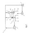
- this valve is integrated within a circulation circuit 2 for circulating a cooling fluid, intended to limit the operating temperature of a heat engine 3.
- the drive fluid in the circuit 2 is provided by a pump 4 whose discharge is connected to the engine 5.
- the circuit 2 further comprises a radiator 5 adapted to lower the temperature of the fluid therethrough by heat exchange with air outside, and a heater 6 for using heat of the fluid passing through it to generate heat, in particular used to warm the passenger compartment of the vehicle to which the engine 3.
- the fluid flowing in the circuit 2 is distributed by means of the valve 1, as detailed below.
- the valve 1 comprises a rigid housing 10, for example made of plastic, on which is releasably and sealingly attached a cover 12.
- the housing 10 is hollow and thus delimits two inner chambers 14 and 16 connected to each other. to one another by a tubular passage 18 of axis XX, defined by the housing.
- the fluid supply of the chamber 14 is provided by a access 20 delimited by both the housing 10 and the cover 12.
- This access 20 thus forms a tubular inlet axis YY substantially perpendicular to the axis XX, which opens into the chamber 14.
- this inlet is provided to be fed by the fluid discharged from the engine 3, after having, if necessary, cooled the latter.
- the housing 10 Opposite the inlet 20, the housing 10 defines a tubular outlet 22 of axis substantially coincident with the Y-axis. This outlet is connected upstream to the chamber 14 and, as shown in Figure 2, is provided downstream to supply the radiator 5.
- the housing 10 delimits a tubular outlet 24 of axis substantially coincident with the axis X-X. This outlet is connected upstream to the chamber 16 and, as shown in FIG. 2, is provided downstream to supply the heater 6.
- the housing 10 delimits a third exit 26 in the form of stepped tube and axis Z-Z substantially perpendicular to the axis X-X and parallel to the axis Y-Y.
- This output is connected upstream to the chamber 16 and, as shown in Figure 2, is provided downstream to supply a bi-pass channel 7, that is to say a path directly returning the fluid leaving the valve up to the pump 4 and the motor 3, without passing previously through the radiator 5, the heater 6 or an equivalent member.
- the valve 1 comprises a first thermostatic element 30 essentially arranged in the chamber 14. More specifically, the thermostatic element 30 comprises, on the one hand, a hollow cylindrical body 32 inside which is stored an expandable material such as only wax and, secondly a piston 34 slidably mounted on the body 32 and one end of which is housed inside this body so that the wax acts on it.
- the element 30 is housed in the housing 10 so that its longitudinal axis, which corresponds to the direction of sliding of the piston 34 relative to the body 32, that is substantially coincident with the axis YY.
- the free end of the piston 34 is received in a blind housing 36 dug in a bearing element 38 integral with the housing 10.
- This support piece is for example integral with the outlet tube 22, forming branches 40 which extend radially to the axis YY and which are spaced from each other along the inner periphery of the outlet 22 to allow the passage of fluid through this outlet.
- the body 32 of the thermostatic element 30 is, at its end opposite the piston 32, received in a rigid ring 42 being able to slide freely relative thereto along the axis Y-Y.
- the ring 42 is fixed vis-à-vis the valve housing 10, branches 43 integral with this ring being for example clamped between the cover 12 and the housing 10.
- the body 32 is secured to a valve 44, for example being force-fitted into the annular body 44A of this valve.
- the valve 44 is thus kinematically connected to the body 32 of the element 30 so that when the piston tends to be moved towards the part 38 under the effect of the expansion of the material contained in the body 32, the body 32 is pushed back.
- this portion 44B consisting of a seal of sealing able to hermetically close the outlet 22 vis-à-vis the chamber 14 when pressed against the seat 46.
- a second thermostatic element 50 is arranged in the second chamber 16 of the valve 1.
- This element has a structure similar to the element 30 and thus comprises a body 52 and a sliding piston 54.
- the longitudinal axis of the element 50 is substantially coincident with the axis ZZ.
- the body 52 of the element 50 is provided fixed relative to the valve housing 10, for example being fitted into a bushing 56 housed and sealingly retained in the chamber 14.
- This sleeve is in the form of a tubular piece ZZ axis.
- a longitudinal end 56A of this bushing is shaped to firmly retain the body 52 while the opposite longitudinal end 56B is axially open towards the outlet 26.
- the bushing 56 matches the inner walls of the chamber 16, while providing radial openings 56C and 56D, aligned along the axis XX, with respectively the passage 18 and the outlet 24.
- seals 58 and 59 are interposed between the socket and the housing.
- the head 62, the body 64 and the tail 66 are kinematically connected to each other so as to be movable only in one piece when using the valve.
- the body 64 and the tail 66 are thus integral with each other while the head 62 is fixed to the body 64 by forced fitting or clipping.
- the slide 60 is guided in translation by a sleeve 70 housed essentially in the outlet tube 26, with the interposition of a seal 74.
- This sleeve is in the form of a tubular piece of axis ZZ open at both ends.
- the bushing 70 thus delimits internally a substantially cylindrical chamber with a circular base 72 coaxial with the chamber 16.
- the bushing 70 forms a heel 76 which reduces the internal diameter of the chamber 72 and thus makes the corresponding portion of the latter flush with the inner wall of the downstream end of the outlet tube 26.
- the inner diameter of the heel 76 is substantially equal to the transverse dimension of the legs of the tail 66 of the drawer 60 so that this heel receives internally and guides in translation this tail.
- the slide 60 is adapted to control the flow of fluid from the chamber 16 to the outlet 26, depending on the temperature of the fluid present in this chamber.
- the drawer 60 is movable between a first closed position of the outlet 26, shown in FIG. 3, and a second closed position of this outlet, represented in FIG. 5, the intermediate positions of the drawer between the two aforementioned positions allowing the flow of fluid through the outlet 22, as shown in Figure 4.
- the outer periphery of the head 62 of the slide 60 has a diameter substantially equal to the inner diameter of the end 56A of the sleeve 56 and is equipped with an annular seal 78 so that when the slide 60 is in its position of Figure 3, the contact between the seal 78 and the sleeve 56 hermetically isolates the chamber 72 vis-à-vis of the chamber 16.
- the body 64 of the slide 60 is equipped, at its connection with the shank 66, with another annular sealing gasket 80 which, when the slide is in its position in FIG. to isolate h hermetically the downstream end of the outlet 26 vis-à-vis the chamber 72.
- the distance d between the seals 78 and 80 is less than the length L of the chamber 72 to allow the flow of fluid around the drawer when the last is in one of its intermediate positions, like that of figure 4.
- the movements of the slide 60 are controlled by the deployment of the piston 54 vis-à-vis the body 52 of the thermostatic element 50: the drawer is in its closed position of Figure 3 when the piston 54 is retracted in the body 52, that is to say when the body 52 is subjected to a lower temperature at a first predetermined temperature value, referred to as ⁇ 1 thereafter, at which the piston begins to deploy, while the slide is in its closed position of FIG. 5 when the body is subjected to a temperature greater than one second predetermined temperature value, called ⁇ 2 thereafter, to which the piston is sufficiently expanded to close the outlet 26 by its seal 80.
- ⁇ 1 a first predetermined temperature value
- a compression spring 82 interposed between the fixed heel 76 and the slide 60, resiliently removes the slide towards the chamber 16 and brings it back into a intermediate position similar to that of Figure 4. If this temperature ⁇ further decreases and its value successively returns below ⁇ 30 and ⁇ 1 , the spring 48 recalls the valve 44 against the seat 46 and the spring 82 recalls the drawer to its position in Figure 3.
- the temperature value ⁇ 30 corresponding to the deployment of the thermostatic element 30 is less than the temperature value ⁇ 2 corresponding to the closing of the outlet 26 by the slide 60 in its position of FIG.
- these two temperature values ⁇ 30 and ⁇ 2 may be provided substantially equal so as to send the incoming fluid to the radiator 4 only at the same time as the supply of the bi-pass channel 7 has been stopped. .
- the valve 1 makes it possible to have a bi-pass outlet through which the flow of fluid entering the valve is prevented when the temperature of this incoming fluid is either less than the first temperature value ⁇ 1 , or greater than the second temperature value ⁇ 2 .
- the first and second predetermined values ⁇ 1 and ⁇ 2 are respectively equal to about 90 and 130 ° C.
- the spool 60 is arranged to control the flow of the fluid towards the bi-pass outlet 26 as a function of the pressure difference prevailing on either side, along the axis ZZ, of the spool, and this independently of its position vis-à-vis the housing 10, that is to say independently of the temperature of the fluid entering the valve.
- the body 64 of the slide 60 is bored to define a substantially cylindrical housing 100 of axis Z-Z. Inside this housing are arranged a ball 102 and a compression spring 104 pressed against this ball.
- the housing 100 On the upstream side of the slide 60, that is to say on the side of its head 62, the housing 100 is hermetically closed by a part 106 delimiting a sealed support seat for the ball 102 and preferably integral with the head 62 via branches 108 spaced apart from each other in a direction orthoradial to the axis ZZ. Between these branches 108, the head 62 is axially recessed so that the fluid contained in the chamber 16 is freely admitted to the seat part 106 where, depending on whether the ball 102 bears or not against this piece, the fluid can be admitted into housing 100.
- the housing 100 freely communicates with the downstream side of the slide 60 via a bore 110 passing axially right through the tail 66.
- the body 64 of the drawer 60 forms an inner shoulder on which the compression spring 104 bears.
- the load of the spring 104 is pre-set so that the ball 102 is kept in pressing contact against the seat part 106 as the pressure difference ⁇ P on either side of the ball 102, that is to say the difference between the pressure in the chamber 16 and the pressure in the bi-pass output 26 downstream of the slide 60 is less than a predetermined threshold P S , for example of the order of about 1 bar.
- the spring 104 is compressed under the driving effect of the ball 102 and the fluid contained in the chamber 16 then passes successively between the branches 108, through the seat part 106, around the ball 102 and through the bore 110 to feed the bi-pass outlet 26, as indicated by the arrow 112.
- the housing 100 and the bore 110 form and a fluid circulation channel between the upstream and downstream of the slide 60.
- the pressostatic ball and spring arrangement described above operates independently of the temperature of the fluid flowing in the valve 1.
- FIG. 7 is shown an example of operation of the valve for which the temperature ⁇ the incoming fluid is greater than the second predetermined temperature value ⁇ 2 and for which a significant overpressure of the chamber 14 is being corrected.
- the slide 60 is firstly manufactured by introducing the ball 102 and the spring 104 into the housing 100. of the body 64, then closing this housing with the head 62.
- the thus assembled slide is then introduced into the sleeve 56 while the latter is disposed outside the housing 10, with the interposition of the spring 82.
- the sleeve 70 is then reported around the head 62 of the drawer 60, then the pre-assembled assembly consisting of the slide and bushes 56 and 70 is introduced inside the housing 10 along the axis ZZ via an opening 120 passing through the wall portion of the housing 10 located next to the bi-pass output 26.
- This pre-assembled assembly is finally held in place in the housing by bringing the cover 12 to the housing 10, as in FIG.
Landscapes
- Engineering & Computer Science (AREA)
- Physics & Mathematics (AREA)
- General Physics & Mathematics (AREA)
- Automation & Control Theory (AREA)
- Chemical & Material Sciences (AREA)
- Combustion & Propulsion (AREA)
- Mechanical Engineering (AREA)
- General Engineering & Computer Science (AREA)
- Fluid Mechanics (AREA)
- Temperature-Responsive Valves (AREA)
Applications Claiming Priority (1)
| Application Number | Priority Date | Filing Date | Title |
|---|---|---|---|
| FR0407641A FR2872854B1 (fr) | 2004-07-08 | 2004-07-08 | Vanne pour un circuit de circulation de fluide et circuit associe a un moteur comportant une telle vanne |
Publications (1)
| Publication Number | Publication Date |
|---|---|
| EP1614873A2 true EP1614873A2 (de) | 2006-01-11 |
Family
ID=34948466
Family Applications (1)
| Application Number | Title | Priority Date | Filing Date |
|---|---|---|---|
| EP05356115A Withdrawn EP1614873A2 (de) | 2004-07-08 | 2005-07-07 | Ventil für einen Fluidiumkreislauf und Kreislauf einer Brennkraftmaschine mit solchem Ventil |
Country Status (2)
| Country | Link |
|---|---|
| EP (1) | EP1614873A2 (de) |
| FR (1) | FR2872854B1 (de) |
Cited By (9)
| Publication number | Priority date | Publication date | Assignee | Title |
|---|---|---|---|---|
| EP1881171A1 (de) * | 2006-07-17 | 2008-01-23 | Behr GmbH & Co. KG | Ventil zur Steuerung eines Kühlmittelstroms für einen Heizkörper eines Kraftfahrzeugs und System mit zumindest einem solchen Ventil |
| EP1918545A3 (de) * | 2006-10-31 | 2009-05-06 | International Engine Intellectual Property Company, LLC. | Kühlmittelregler für einen Verbrennungsmotor |
| WO2016181052A1 (fr) * | 2015-05-13 | 2016-11-17 | Peugeot Citroen Automobiles Sa | Boitier de sortie de fluide de refroidissement d'un moteur |
| FR3036135A1 (fr) * | 2015-05-13 | 2016-11-18 | Peugeot Citroen Automobiles Sa | Circuit de refroidissement d’un moteur |
| FR3040739A1 (fr) * | 2015-09-08 | 2017-03-10 | Renault Sa | Systeme de refroidissement pour un moteur a combustion interne, notamment de vehicule automobile |
| WO2017134368A1 (fr) * | 2016-02-05 | 2017-08-10 | Peugeot Citroen Automobiles Sa | Procede de protection d'un circuit de fluide de refroidissement d'un moteur contre une surpression interne |
| CN110005843A (zh) * | 2019-04-24 | 2019-07-12 | 杭州初始服饰有限公司 | 一种循环导气阀门 |
| WO2020177963A1 (de) * | 2019-03-05 | 2020-09-10 | Bayerische Motoren Werke Aktiengesellschaft | Kühlmittelkreislauf in einem fahrzeug |
| CN117803736A (zh) * | 2024-02-28 | 2024-04-02 | 四川省简阳市川力机械制造有限责任公司 | 一种切断阀 |
Citations (1)
| Publication number | Priority date | Publication date | Assignee | Title |
|---|---|---|---|---|
| DE2932078A1 (de) | 1979-08-08 | 1981-02-26 | Daimler Benz Ag | Regelthermostat fuer den kuehlkreis einer fluessigkeitsgekuehlten brennkraftmaschine |
Family Cites Families (5)
| Publication number | Priority date | Publication date | Assignee | Title |
|---|---|---|---|---|
| US1791756A (en) * | 1926-03-20 | 1931-02-10 | Bishop & Babcock Mfg Co | Control means for cooling systems for internal-combustion engines |
| GB461707A (en) * | 1935-10-30 | 1937-02-23 | James Edwin Ellor | Improvements in or relating to bye-pass valves for oil coolers |
| DE2320447A1 (de) * | 1973-04-21 | 1974-11-07 | Daimler Benz Ag | Kuehlwasserregelventil, insbesondere zur regelung der kuehlwassertemperatur von kraftfahrzeugen |
| US4344564A (en) * | 1981-02-23 | 1982-08-17 | Gould Inc. | Thermal by-pass valve with integral pressure relief |
| DE4412482B4 (de) * | 1994-04-12 | 2005-11-10 | Gustav Wahler Gmbh U. Co | Thermostatventil |
-
2004
- 2004-07-08 FR FR0407641A patent/FR2872854B1/fr not_active Expired - Lifetime
-
2005
- 2005-07-07 EP EP05356115A patent/EP1614873A2/de not_active Withdrawn
Patent Citations (1)
| Publication number | Priority date | Publication date | Assignee | Title |
|---|---|---|---|---|
| DE2932078A1 (de) | 1979-08-08 | 1981-02-26 | Daimler Benz Ag | Regelthermostat fuer den kuehlkreis einer fluessigkeitsgekuehlten brennkraftmaschine |
Cited By (14)
| Publication number | Priority date | Publication date | Assignee | Title |
|---|---|---|---|---|
| EP1881171A1 (de) * | 2006-07-17 | 2008-01-23 | Behr GmbH & Co. KG | Ventil zur Steuerung eines Kühlmittelstroms für einen Heizkörper eines Kraftfahrzeugs und System mit zumindest einem solchen Ventil |
| EP1918545A3 (de) * | 2006-10-31 | 2009-05-06 | International Engine Intellectual Property Company, LLC. | Kühlmittelregler für einen Verbrennungsmotor |
| WO2016181052A1 (fr) * | 2015-05-13 | 2016-11-17 | Peugeot Citroen Automobiles Sa | Boitier de sortie de fluide de refroidissement d'un moteur |
| FR3036134A1 (fr) * | 2015-05-13 | 2016-11-18 | Peugeot Citroen Automobiles Sa | Boitier de sortie de fluide de refroidissement d’un moteur |
| FR3036135A1 (fr) * | 2015-05-13 | 2016-11-18 | Peugeot Citroen Automobiles Sa | Circuit de refroidissement d’un moteur |
| FR3040739A1 (fr) * | 2015-09-08 | 2017-03-10 | Renault Sa | Systeme de refroidissement pour un moteur a combustion interne, notamment de vehicule automobile |
| WO2017134368A1 (fr) * | 2016-02-05 | 2017-08-10 | Peugeot Citroen Automobiles Sa | Procede de protection d'un circuit de fluide de refroidissement d'un moteur contre une surpression interne |
| FR3047514A1 (fr) * | 2016-02-05 | 2017-08-11 | Peugeot Citroen Automobiles Sa | Procede de protection d’un circuit de fluide de refroidissement d’un moteur contre une surpression interne |
| WO2020177963A1 (de) * | 2019-03-05 | 2020-09-10 | Bayerische Motoren Werke Aktiengesellschaft | Kühlmittelkreislauf in einem fahrzeug |
| CN113227553A (zh) * | 2019-03-05 | 2021-08-06 | 宝马股份公司 | 在车辆中的冷却剂回路 |
| US12276223B2 (en) | 2019-03-05 | 2025-04-15 | Bayerische Motoren Werke Aktiengesellschaft | Coolant circuit in a vehicle |
| CN110005843A (zh) * | 2019-04-24 | 2019-07-12 | 杭州初始服饰有限公司 | 一种循环导气阀门 |
| CN117803736A (zh) * | 2024-02-28 | 2024-04-02 | 四川省简阳市川力机械制造有限责任公司 | 一种切断阀 |
| CN117803736B (zh) * | 2024-02-28 | 2024-04-26 | 四川省简阳市川力机械制造有限责任公司 | 一种切断阀 |
Also Published As
| Publication number | Publication date |
|---|---|
| FR2872854A1 (fr) | 2006-01-13 |
| FR2872854B1 (fr) | 2009-05-08 |
Similar Documents
| Publication | Publication Date | Title |
|---|---|---|
| FR2957395A1 (fr) | Vanne thermostatique a manchon | |
| EP0235472B1 (de) | Mischungsthermostatventile für den Flüssigkeitskreislauf bei Verbrennungsmotoren | |
| WO2009019407A1 (fr) | Vanne thermostatique à manchon, moteur thermique associé à un circuit de refroidissement comportant une telle vanne, et procédé de fabrication du manchon d'une telle vanne | |
| EP1614873A2 (de) | Ventil für einen Fluidiumkreislauf und Kreislauf einer Brennkraftmaschine mit solchem Ventil | |
| WO2008093027A2 (fr) | Vanne thermostatique de regulation d'un fluide, circuit de liquide de refroidissement incorporant une telle vanne et procede de fabrication d'une telle vanne | |
| EP1674689B1 (de) | Thermostatventil für Regelung eines Fluidiums und Kühlungskreis ausgerüstet mit solchem Ventil | |
| WO2021123021A1 (fr) | Dispositif de commande de l'écoulement d'un fluide | |
| EP1486843B1 (de) | Thermostatventil für einen Flüssigkeitsströmungskreis und Verbrennungsmotor mit einem Flüssigkeitsströmungskreis, der diese Ventil beinhaltet | |
| FR2827361A1 (fr) | Vanne de commande a fonctionnement securise pour circuit de circulation de fluide | |
| FR2961917A1 (fr) | Vanne thermostatique de regulation d'un fluide, notamment d'un fluide de refroidissement d'un moteur thermique | |
| EP2187016A1 (de) | Kühlmittelkreislauf eines Motors | |
| EP1607818B1 (de) | Thermostatventil für einen Kühlmittelkreislauf | |
| EP3724740B1 (de) | Thermostatventil | |
| FR3107329A1 (fr) | Vanne multivoies à obturateur rotatif et à commande par pression hydraulique | |
| WO2021151921A1 (fr) | Dispositif thermostatique pour réguler la circulation d'un fluide, ainsi que vanne thermostatique comprenant un tel dispositif | |
| FR2904064A1 (fr) | Element thermostatique,vanne de regulation comportant un tel element et circuit de liquide de refroidissement incorporant une telle vanne | |
| FR3066538A1 (fr) | Dispositif de controle de la distribution d'huile pour un moteur thermique | |
| WO2016169958A1 (fr) | Dispositif thermostatique de régulation de la circulation d'un fluide, ainsi que vanne thermostatique comprenant un tel dispositif | |
| EP4049107B1 (de) | Thermostatventil | |
| WO2020207993A1 (fr) | Cartouche thermostatique | |
| FR3137429A1 (fr) | Vanne thermostatique à manchon | |
| FR3132134A1 (fr) | Vanne thermostatique | |
| WO2024003144A1 (fr) | Vanne thermostatique à manchon | |
| EP3477415B1 (de) | Thermostatventil | |
| FR3143784A1 (fr) | Ensemble thermostatique, notamment cartouche thermostatique |
Legal Events
| Date | Code | Title | Description |
|---|---|---|---|
| PUAI | Public reference made under article 153(3) epc to a published international application that has entered the european phase |
Free format text: ORIGINAL CODE: 0009012 |
|
| AK | Designated contracting states |
Kind code of ref document: A2 Designated state(s): AT BE BG CH CY CZ DE DK EE ES FI FR GB GR HU IE IS IT LI LT LU LV MC NL PL PT RO SE SI SK TR |
|
| AX | Request for extension of the european patent |
Extension state: AL BA HR MK YU |
|
| STAA | Information on the status of an ep patent application or granted ep patent |
Free format text: STATUS: THE APPLICATION HAS BEEN WITHDRAWN |
|
| 18W | Application withdrawn |
Effective date: 20090214 |