EP1614874A1 - Brennkraftmaschine mit einem Kolben mit einer Höhlung mit kegelstumpfförmiger Wände - Google Patents
Brennkraftmaschine mit einem Kolben mit einer Höhlung mit kegelstumpfförmiger Wände Download PDFInfo
- Publication number
- EP1614874A1 EP1614874A1 EP05300560A EP05300560A EP1614874A1 EP 1614874 A1 EP1614874 A1 EP 1614874A1 EP 05300560 A EP05300560 A EP 05300560A EP 05300560 A EP05300560 A EP 05300560A EP 1614874 A1 EP1614874 A1 EP 1614874A1
- Authority
- EP
- European Patent Office
- Prior art keywords
- revolution
- cavity
- axis
- piston
- fuel
- Prior art date
- Legal status (The legal status is an assumption and is not a legal conclusion. Google has not performed a legal analysis and makes no representation as to the accuracy of the status listed.)
- Withdrawn
Links
Images

Classifications
-
- F—MECHANICAL ENGINEERING; LIGHTING; HEATING; WEAPONS; BLASTING
- F02—COMBUSTION ENGINES; HOT-GAS OR COMBUSTION-PRODUCT ENGINE PLANTS
- F02B—INTERNAL-COMBUSTION PISTON ENGINES; COMBUSTION ENGINES IN GENERAL
- F02B23/00—Other engines characterised by special shape or construction of combustion chambers to improve operation
- F02B23/02—Other engines characterised by special shape or construction of combustion chambers to improve operation with compression ignition
- F02B23/06—Other engines characterised by special shape or construction of combustion chambers to improve operation with compression ignition the combustion space being arranged in working piston
- F02B23/0672—Omega-piston bowl, i.e. the combustion space having a central projection pointing towards the cylinder head and the surrounding wall being inclined towards the cylinder center axis
-
- F—MECHANICAL ENGINEERING; LIGHTING; HEATING; WEAPONS; BLASTING
- F02—COMBUSTION ENGINES; HOT-GAS OR COMBUSTION-PRODUCT ENGINE PLANTS
- F02B—INTERNAL-COMBUSTION PISTON ENGINES; COMBUSTION ENGINES IN GENERAL
- F02B23/00—Other engines characterised by special shape or construction of combustion chambers to improve operation
- F02B23/02—Other engines characterised by special shape or construction of combustion chambers to improve operation with compression ignition
- F02B23/06—Other engines characterised by special shape or construction of combustion chambers to improve operation with compression ignition the combustion space being arranged in working piston
- F02B23/0696—W-piston bowl, i.e. the combustion space having a central projection pointing towards the cylinder head and the surrounding wall being inclined towards the cylinder wall
-
- Y—GENERAL TAGGING OF NEW TECHNOLOGICAL DEVELOPMENTS; GENERAL TAGGING OF CROSS-SECTIONAL TECHNOLOGIES SPANNING OVER SEVERAL SECTIONS OF THE IPC; TECHNICAL SUBJECTS COVERED BY FORMER USPC CROSS-REFERENCE ART COLLECTIONS [XRACs] AND DIGESTS
- Y02—TECHNOLOGIES OR APPLICATIONS FOR MITIGATION OR ADAPTATION AGAINST CLIMATE CHANGE
- Y02T—CLIMATE CHANGE MITIGATION TECHNOLOGIES RELATED TO TRANSPORTATION
- Y02T10/00—Road transport of goods or passengers
- Y02T10/10—Internal combustion engine [ICE] based vehicles
- Y02T10/12—Improving ICE efficiencies
Definitions
- the invention relates to an internal combustion engine.
- the invention more particularly relates to an internal combustion engine, with compression ignition and direct injection, of the type which comprises at least one combustion chamber which is delimited on the one hand by a cylinder head of the engine and on the other by a piston , mounted movably in the chamber, in a free upper face which opens a bowl-shaped revolution cavity, and of the type which comprises a fuel injector arranged substantially in the axis of the cavity of revolution of which at least one orifice is capable of spraying a jet of fuel along an associated spraying axis associated in the bowl-shaped revolution cavity, in particular when the piston reaches a position called top dead center.
- This type of piston provided with a cavity of revolution, is more particularly intended for engines of the "diesel" direct injection type, because it allows a mixture of air and fuel more homogeneous in the chamber.
- the fuel when injected through the orifices of the fuel injector, determines a cone whose opening, also known as the "slick angle", is essential.
- the combustion chamber comprises an injector whose nappe angle is relatively high, ie typically of the order of 140 to 160 degrees.
- This injector is implanted in the cylinder head so that the points of impact of the fuel jets are placed at the periphery of the piston bowl.
- This configuration poses many problems. Indeed, during its spraying, the fuel can be brought to interact with itself and lead to a high production of soot in areas where the oxygen of the air is scarce, the jet of fuel overlapping at the same time. inside the bowl before accessing the free space delimited between the upper surface of the piston and the cylinder head. Furthermore, the exploitation of oxygen in the free space delimited between the upper surface of the piston and the cylinder head is not optimal because the fuel jets do not reach this zone quickly. Finally, this type of combustion chamber does not allow to perform fuel injection before the piston reaches the top dead center, because the high angle of the sheet leads to a watering of the peripheral wall of the cylinder, with as a result a high dilution of the lubricant that covers it.
- the combustion chamber comprises an injector whose lap angle is low, ie typically of the order of 50 to 60 degrees.
- This injector is implanted in the cylinder head so that the points of impact of the fuel jets are placed in the center of the bowl of the piston, on a central protuberance of the bowl.
- This configuration avoids the watering of the cylinder wall when a fuel injection is performed before the piston reaches the top dead center.
- the zone located in the center of the bowl does not benefit from an optimal distribution of the air / fuel mixture.
- the invention proposes a configuration of the combustion chamber to ensure optimal distribution of fuel in all points of the combustion chamber.
- the invention proposes a motor of the type described above, characterized in that the spraying axis forms with the axis of the cavity of revolution an angle of between 40 and 60 degrees and in that the cavity of revolution comprises at least one substantially frustoconical wall of revolution arranged perpendicularly to the spraying axis, to dissipate a portion of the energy of the jet of fuel at the point of impact of the jet on the wall of revolution and thus prevent said jet from overlapping.
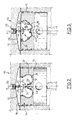
- FIG. 1 shows the detail of a combustion chamber 10 of an internal combustion engine with compression ignition and direct injection.
- the combustion chamber 10 is delimited on the one hand by a cylinder head 12 of the engine and on the other by a piston 14, movably mounted in a cylinder 13 of the chamber 10, in a free upper face 16 from which a 18 bowl-shaped revolution cavity, and it comprises a fuel injector 20 arranged substantially in the axis "A" of the cavity 18 of revolution.
- At least one orifice 22 of the injector 20 is capable of spraying a fuel jet 24 along an axis "B 1 ", "B 2 ", or “B 3 " of the associated determined atomization in the cavity 18 of revolution in the form of bowl, especially when the piston 14 reaches a position called top dead center.
- the chamber 10 is supplied with air by valves, which, for ease of reading the figures, have not been shown and are arranged in a plane different from the sectional plane of Figures 1 to 3.
- the spindle is the generator of a theoretical cone whose opening, also called “angle of the sheet” is paramount.
- this ply angle corresponds to twice the angle formed between the spraying axis and the axis "A" of the cavity of revolution
- the combustion chamber comprises an injector 22 whose angle " ⁇ 1 " of web is relatively high, ie typically of the order of 140 to 160. degrees.
- Spray axis "B 1 " therefore forms an angle " ⁇ 1 " of 70 to 80 degrees with axis "A".
- This injector 22 is implanted in the cylinder head so that the points of impact 26 of the fuel jets 24 are placed at the periphery of the internal cavity 18 of the piston 14.
- this type of combustion chamber 10 does not allow to perform fuel injection before the piston 14 reaches the top dead center, because the angle " ⁇ 1 " of high sheet leads to a watering of the wall cylinder 13, resulting in a high dilution of the lubricant trusting who covers her.
- the combustion chamber 10 comprises an injector 20 whose angle " ⁇ 2 " of ply is low, ie typically of the order of 50 to 60 degrees.
- the axis "B 2 " spraying forms an angle " ⁇ 2 " of 25 to 30 degrees with the axis "A”.
- This injector 20 is implanted in the yoke 12 so that the impact points 26 of the fuel jets 24 are placed in the center of the inner cavity 18 of the piston 14, substantially on a central protuberance 30 of the bowl.
- This configuration avoids the watering of the cylinder wall when a fuel injection is performed before the piston reaches the top dead center.
- the invention overcomes these disadvantages by providing a configuration of the combustion chamber to ensure optimum distribution of fuel in all points of the combustion chamber.
- the invention proposes a motor of the type described above, characterized in that the spindle "B 3 " forms with the axis "A" of the cavity 18 of revolution an angle " ⁇ 3 " between 40 and 60 degrees, ie corresponding to an angle " ⁇ 3 " of sheet comprised between 80 and 120 degrees, and in that the cavity 18 of revolution comprises at least one wall 36 of substantially frustoconical revolution arranged perpendicularly. of the "B" spraying axis, to dissipate some of the energy the jet of fuel at the point of impact 26 of the jet 24 on the wall 36 of revolution and thus prevent said jet 24 from overlapping.
- the frustoconical wall 36 of revolution extends equidistantly on either side of the point of impact 26 of the jet 24 so as to cause a uniform division of the fuel jet into two jets 24a and 24b which have been shown in phantom in Figure 3, which allows to ensure a uniform mixture of fuel with the oxygen contained in the cavity 18 of revolution.
- This configuration makes it possible to ensure a homogeneous mixture of the air and the fuel before it is diffused in the zone 28 arranged between the piston 14 and the cylinder head 12.
- the central protuberance 30 is shaped as a dome whose vertex 40 is of a determined curvature and whose flanks 42 are contiguous with the internal diameter of the frustoconical wall 36 of revolution. This configuration ensures a flow of gas between the wall 36 and the central protuberance 30 which is free from any disturbance
- the peripheral flange 38 comprises at least one convex ring annular portion 44 forming a bead which extends over a portion of the truncated conical wall 36 and which is flush with the free upper surface 16 of the piston 14.
- the injector 20 comprises at least three orifices 22 angularly distributed regularly around the axis "A" of the cavity 18 of revolution.
- the cavity 18 of piston revolution 14 is a determining factor to ensure a good flow of fuel
- the cavity 18 revolution is preferably performed by machining the piston head 14.
- the invention therefore makes it possible to make a significant improvement in the performance of a direct injection compression engine.
Landscapes
- Engineering & Computer Science (AREA)
- Chemical & Material Sciences (AREA)
- Combustion & Propulsion (AREA)
- Mechanical Engineering (AREA)
- General Engineering & Computer Science (AREA)
- Fuel-Injection Apparatus (AREA)
- Combustion Methods Of Internal-Combustion Engines (AREA)
Applications Claiming Priority (1)
| Application Number | Priority Date | Filing Date | Title |
|---|---|---|---|
| FR0407679A FR2872855A1 (fr) | 2004-07-09 | 2004-07-09 | Moteur a combustion interne comportant un piston muni d'une cavite a paroi tronconique |
Publications (1)
| Publication Number | Publication Date |
|---|---|
| EP1614874A1 true EP1614874A1 (de) | 2006-01-11 |
Family
ID=34948471
Family Applications (1)
| Application Number | Title | Priority Date | Filing Date |
|---|---|---|---|
| EP05300560A Withdrawn EP1614874A1 (de) | 2004-07-09 | 2005-07-05 | Brennkraftmaschine mit einem Kolben mit einer Höhlung mit kegelstumpfförmiger Wände |
Country Status (2)
| Country | Link |
|---|---|
| EP (1) | EP1614874A1 (de) |
| FR (1) | FR2872855A1 (de) |
Cited By (4)
| Publication number | Priority date | Publication date | Assignee | Title |
|---|---|---|---|---|
| DE102006008567A1 (de) * | 2006-02-22 | 2007-08-23 | Fev Motorentechnik Gmbh | Brennraummuldengeometrie für Einspritzdüsen mit mehr als einer Düsenlochreihe |
| US20150027408A1 (en) * | 2011-10-14 | 2015-01-29 | Vladimir Borissovskiy | Diesel engine combustion chamber, method for igniting a fuel-air mixture in a combustion chamber of a diesel engine and diesel engine |
| US10738682B2 (en) | 2015-12-22 | 2020-08-11 | Volvo Truck Corporation | Piston crown for an internal combustion engine |
| CN113719342A (zh) * | 2021-07-29 | 2021-11-30 | 东风商用车有限公司 | 双卷流燃烧室的射流-压燃燃烧系统 |
Citations (10)
| Publication number | Priority date | Publication date | Assignee | Title |
|---|---|---|---|---|
| US2828724A (en) * | 1953-10-08 | 1958-04-01 | Schweizerische Lokomotiv | Internal combustion engines of the injection type |
| US3083700A (en) * | 1961-12-08 | 1963-04-02 | Paul D Madak | Internal combustion engine construction |
| GB1473696A (en) * | 1974-07-18 | 1977-05-18 | Isuzu Motors Ltd | Direct fuel injection type diesel engine and a piston therefor |
| JPH02233822A (ja) * | 1989-03-06 | 1990-09-17 | Isuzu Motors Ltd | エンジンのピストン |
| JPH02248615A (ja) * | 1989-03-22 | 1990-10-04 | Isuzu Motors Ltd | エンジンのピストン |
| JPH04279723A (ja) * | 1991-01-09 | 1992-10-05 | Yanmar Diesel Engine Co Ltd | 直接噴射式ディーゼル機関の燃焼装置 |
| US5373820A (en) * | 1992-04-09 | 1994-12-20 | Sanshin Kogyo Kabushiki Kaisha | Cylinder fuel injection type two-cycle engine |
| JPH0893550A (ja) * | 1994-09-26 | 1996-04-09 | Isuzu Motors Ltd | 直噴式ディーゼルエンジンの燃焼室 |
| JP2003293773A (ja) * | 2002-03-29 | 2003-10-15 | Tokyo Gas Co Ltd | 副室式エンジン |
| EP1357274A1 (de) * | 2002-04-24 | 2003-10-29 | Renault s.a.s. | Brennkammer für eine mehrzylindrige, selbstzündende Brennkraftmaschine, insbesondere für einen direkteingespritzen Dieselmotor sowie zugehöriger Motor |
-
2004
- 2004-07-09 FR FR0407679A patent/FR2872855A1/fr active Pending
-
2005
- 2005-07-05 EP EP05300560A patent/EP1614874A1/de not_active Withdrawn
Patent Citations (10)
| Publication number | Priority date | Publication date | Assignee | Title |
|---|---|---|---|---|
| US2828724A (en) * | 1953-10-08 | 1958-04-01 | Schweizerische Lokomotiv | Internal combustion engines of the injection type |
| US3083700A (en) * | 1961-12-08 | 1963-04-02 | Paul D Madak | Internal combustion engine construction |
| GB1473696A (en) * | 1974-07-18 | 1977-05-18 | Isuzu Motors Ltd | Direct fuel injection type diesel engine and a piston therefor |
| JPH02233822A (ja) * | 1989-03-06 | 1990-09-17 | Isuzu Motors Ltd | エンジンのピストン |
| JPH02248615A (ja) * | 1989-03-22 | 1990-10-04 | Isuzu Motors Ltd | エンジンのピストン |
| JPH04279723A (ja) * | 1991-01-09 | 1992-10-05 | Yanmar Diesel Engine Co Ltd | 直接噴射式ディーゼル機関の燃焼装置 |
| US5373820A (en) * | 1992-04-09 | 1994-12-20 | Sanshin Kogyo Kabushiki Kaisha | Cylinder fuel injection type two-cycle engine |
| JPH0893550A (ja) * | 1994-09-26 | 1996-04-09 | Isuzu Motors Ltd | 直噴式ディーゼルエンジンの燃焼室 |
| JP2003293773A (ja) * | 2002-03-29 | 2003-10-15 | Tokyo Gas Co Ltd | 副室式エンジン |
| EP1357274A1 (de) * | 2002-04-24 | 2003-10-29 | Renault s.a.s. | Brennkammer für eine mehrzylindrige, selbstzündende Brennkraftmaschine, insbesondere für einen direkteingespritzen Dieselmotor sowie zugehöriger Motor |
Non-Patent Citations (4)
| Title |
|---|
| PATENT ABSTRACTS OF JAPAN vol. 014, no. 549 (M - 1055) 6 December 1990 (1990-12-06) * |
| PATENT ABSTRACTS OF JAPAN vol. 014, no. 575 (M - 1062) 20 December 1990 (1990-12-20) * |
| PATENT ABSTRACTS OF JAPAN vol. 017, no. 080 (M - 1368) 17 February 1993 (1993-02-17) * |
| PATENT ABSTRACTS OF JAPAN vol. 1996, no. 08 30 August 1996 (1996-08-30) * |
Cited By (5)
| Publication number | Priority date | Publication date | Assignee | Title |
|---|---|---|---|---|
| DE102006008567A1 (de) * | 2006-02-22 | 2007-08-23 | Fev Motorentechnik Gmbh | Brennraummuldengeometrie für Einspritzdüsen mit mehr als einer Düsenlochreihe |
| US20150027408A1 (en) * | 2011-10-14 | 2015-01-29 | Vladimir Borissovskiy | Diesel engine combustion chamber, method for igniting a fuel-air mixture in a combustion chamber of a diesel engine and diesel engine |
| US10041439B2 (en) * | 2011-10-14 | 2018-08-07 | Vladimir Borissovskiy | Combustion chamber, method for igniting a fuel-air mixture in a combustion chamber of an internal combustion engine and internal combustion engine |
| US10738682B2 (en) | 2015-12-22 | 2020-08-11 | Volvo Truck Corporation | Piston crown for an internal combustion engine |
| CN113719342A (zh) * | 2021-07-29 | 2021-11-30 | 东风商用车有限公司 | 双卷流燃烧室的射流-压燃燃烧系统 |
Also Published As
| Publication number | Publication date |
|---|---|
| FR2872855A1 (fr) | 2006-01-13 |
Similar Documents
| Publication | Publication Date | Title |
|---|---|---|
| CH516079A (fr) | Moteur à allumage par compression | |
| EP1599671B1 (de) | Kraftstoffeinspritzventil für brennkraftmaschine | |
| FR2537651A1 (fr) | Moteur a combustion interne, a compression d'air et allumage independant | |
| EP1614874A1 (de) | Brennkraftmaschine mit einem Kolben mit einer Höhlung mit kegelstumpfförmiger Wände | |
| FR2894614A1 (fr) | Moteur a combustion interne comportant un piston comportant un bossage de geometrie complexe | |
| FR2927121A1 (fr) | Moteur a combustion interne comportant un bol de combustion a double cavite pour un injecteur ultrasonore | |
| FR2947009A1 (fr) | Piston pour chambre de combustion de moteur diesel. | |
| EP1215377B1 (de) | Gaseinlasssystem für einen Brennkammer, dessen Einlasskanal eine Rille aufweist | |
| EP1645734B1 (de) | Brennkraftmaschine mit einem Einspritzventil mit optimierten Kraftstoffspritzstrahlen | |
| FR3114614A1 (fr) | Dispositif d’allumage à préchambre pour moteur à combustion interne à allumage commandé | |
| FR2877056A1 (fr) | Injecteur de carburant pour moteur a combustion interne comportant des trous d'injection de permeabilite differente | |
| WO2009101318A1 (fr) | Moteur a combustion interne comportant un bol de combustion pour un injecteur de type ultrasonore | |
| EP0661423B1 (de) | Dieselbrennkraftmaschine mit am Ausgang der Wirbelkammer gesteuertem Gasstrom | |
| FR2880385A1 (fr) | Moteur a combustion interne comportant un piston a bol de combustion muni d'un bossage incline | |
| FR2886982A1 (fr) | Piston pour moteur a injection directe | |
| FR2713282A1 (fr) | Moteur à allumage par compression à injection directe, à combustion améliorée. | |
| FR2801638A1 (fr) | Systeme d'admission de gaz dans un moteur a combustion | |
| FR3095499A1 (fr) | Injecteur d’un melange d’air et de carburant pour une chambre de combustion d’une turbomachine | |
| FR2889258A3 (fr) | Injecteur de carburant de vehicule automobile comportant un dome d'injection tronque | |
| FR2887304A1 (fr) | Moteur a combustion interne comprenant un injecteur de carburant adapte pour le demarrage dudit moteur | |
| FR2864581A1 (fr) | Piston, moteur a combustion interne comportant un tel piston et procede de commande d'un tel moteur | |
| EP0916824A1 (de) | Fremdegezündete Brennkraftmaschine mit direkter Kraftstoffeinspritzung und verschobener Zündkerze | |
| WO2006059037A1 (fr) | Moteur diesel a injcetion directe et procede d'injection de combustible dans une chambre de combustion d'un tel moteur. | |
| FR2896536A1 (fr) | Moteur a chambre de combustion munie d'un dome comportant des moyens generateurs de turbulence | |
| FR2880923A1 (fr) | Chambre de combustion d'un moteur a allumage par compression avec un injecteur de carburant decentre par rapport a l'axe du cylindre |
Legal Events
| Date | Code | Title | Description |
|---|---|---|---|
| PUAI | Public reference made under article 153(3) epc to a published international application that has entered the european phase |
Free format text: ORIGINAL CODE: 0009012 |
|
| AK | Designated contracting states |
Kind code of ref document: A1 Designated state(s): AT BE BG CH CY CZ DE DK EE ES FI FR GB GR HU IE IS IT LI LT LU LV MC NL PL PT RO SE SI SK TR |
|
| AX | Request for extension of the european patent |
Extension state: AL BA HR MK YU |
|
| 17P | Request for examination filed |
Effective date: 20060621 |
|
| 17Q | First examination report despatched |
Effective date: 20060724 |
|
| AKX | Designation fees paid |
Designated state(s): AT BE BG CH CY CZ DE DK EE ES FI FR GB GR HU IE IS IT LI LT LU LV MC NL PL PT RO SE SI SK TR |
|
| STAA | Information on the status of an ep patent application or granted ep patent |
Free format text: STATUS: THE APPLICATION IS DEEMED TO BE WITHDRAWN |
|
| 18D | Application deemed to be withdrawn |
Effective date: 20140626 |