EP1614877A1 - Stromerzeuger - Google Patents
Stromerzeuger Download PDFInfo
- Publication number
- EP1614877A1 EP1614877A1 EP05076370A EP05076370A EP1614877A1 EP 1614877 A1 EP1614877 A1 EP 1614877A1 EP 05076370 A EP05076370 A EP 05076370A EP 05076370 A EP05076370 A EP 05076370A EP 1614877 A1 EP1614877 A1 EP 1614877A1
- Authority
- EP
- European Patent Office
- Prior art keywords
- set according
- case
- platform
- fresh air
- chamber
- Prior art date
- Legal status (The legal status is an assumption and is not a legal conclusion. Google has not performed a legal analysis and makes no representation as to the accuracy of the status listed.)
- Withdrawn
Links
- 238000002485 combustion reaction Methods 0.000 claims abstract description 8
- 238000001816 cooling Methods 0.000 claims abstract description 7
- 239000002828 fuel tank Substances 0.000 claims description 2
- 230000030279 gene silencing Effects 0.000 description 3
- 239000002184 metal Substances 0.000 description 2
- 208000003443 Unconsciousness Diseases 0.000 description 1
- 239000000498 cooling water Substances 0.000 description 1
- 230000001419 dependent effect Effects 0.000 description 1
- 210000005069 ears Anatomy 0.000 description 1
- 238000012423 maintenance Methods 0.000 description 1
- 230000000284 resting effect Effects 0.000 description 1
- 230000001743 silencing effect Effects 0.000 description 1
- XLYOFNOQVPJJNP-UHFFFAOYSA-N water Substances O XLYOFNOQVPJJNP-UHFFFAOYSA-N 0.000 description 1
Images


Classifications
-
- F—MECHANICAL ENGINEERING; LIGHTING; HEATING; WEAPONS; BLASTING
- F02—COMBUSTION ENGINES; HOT-GAS OR COMBUSTION-PRODUCT ENGINE PLANTS
- F02B—INTERNAL-COMBUSTION PISTON ENGINES; COMBUSTION ENGINES IN GENERAL
- F02B77/00—Component parts, details or accessories, not otherwise provided for
- F02B77/11—Thermal or acoustic insulation
- F02B77/13—Acoustic insulation
-
- F—MECHANICAL ENGINEERING; LIGHTING; HEATING; WEAPONS; BLASTING
- F02—COMBUSTION ENGINES; HOT-GAS OR COMBUSTION-PRODUCT ENGINE PLANTS
- F02B—INTERNAL-COMBUSTION PISTON ENGINES; COMBUSTION ENGINES IN GENERAL
- F02B63/00—Adaptations of engines for driving pumps, hand-held tools or electric generators; Portable combinations of engines with engine-driven devices
- F02B63/04—Adaptations of engines for driving pumps, hand-held tools or electric generators; Portable combinations of engines with engine-driven devices for electric generators
- F02B63/044—Adaptations of engines for driving pumps, hand-held tools or electric generators; Portable combinations of engines with engine-driven devices for electric generators the engine-generator unit being placed on a frame or in an housing
Definitions
- the present finding refers to improvements made to sets for generating current in generals, be they fixed or mobile.
- generator sets a typical use of which is in emergencies, for example to provide electrical energy to the essential apparatuses of a hospital in the case of a black-out, briefly comprise an electrical machine, like an alternator, which is driven by a combustion engine, generally a Diesel-cycle internal combustion engine, all being installed on a suitable platform.
- a combustion engine generally a Diesel-cycle internal combustion engine
- the internal combustion engine is generally cooled by water, which flows in a radiator that is crossed by a flow of air driven by a fan controlled by the engine, and intended to cool down both the engine and the alternator.
- generator sets are generally rather noisy and therefore there is a requirement to cut out or reduce as much as possible its noisiness, without of course altering the characteristics of the overall cooling system for obvious reasons.
- the main purpose of the finding is, indeed, that of providing a silencing system for such generator sets that is able to fulfil the quoted requirement.
- Another purpose of the finding is that of making a sound-proofing system that, as well as having excellent silencing properties, allows access to the various parts of the generator set, for example for control and maintenance interventions, both general and specific, in a particularly simple, quick and easy manner.
- a further purpose consists of making a sound-proofing system capable of achieving the quoted goals in the context of a simple, rational, functional, strong and cost-effective constructive solution.
- said generator set is of the type outlined in the preamble, or rather it comprises an internal combustion engine that is fitted onto a platform, and at the opposite axial ends of which are associated a current generator and a cooling fan suitable for creating a flow of fresh air that flows generally according to the direction taken up by the axis of the engine, typically in the direction that goes from the current generator to the cooling fan.
- said platform is provided with an overlying generally parallelepiped sound-proofing shell that provides, at the bottom, a surrounding case that contains the engine and its additional parts, and takes care of channelling the cooling air flow, and at the top, a service chamber that provides two manifolds for fresh air and exhaust air, respectively, the first of which places the outside in communication with the underlying area of the case intended for the current generator, and the second of which places the underlying area of the case intended for the fan in communication with the outside.
- the flow of air between case and manifolds takes lace through a horizontal wall that separates case and chamber.
- Said horizontal wall preferably consists of a sound-absorbing baffle.
- the set is practically completely surrounded by a sound-proofed jacket, obviously apart from the ports for the passage of fresh air coming in and exhaust air going out, respectively, which allows a drastic reduction in noise as has been able to be seen following specific tests carried out on various types of generator sets, obviously tested with and without the silencing system according to the finding.
- said sound-proofed shell preferably consists of a box-shaped body that is open at the bottom suitable for resting on the engine-carrying platform, and removably fixed there through threaded members so as to totally uncover the engine in a short space of time.
- said box-shaped body has hatches and removable panels intended for localised interventions.
- the platform 1 can be of the type intended to be fixed to the floor, or of the type suitable for being arranged on a mobile, self-propelled or dragged means.
- the generator set is of the known type and comprises, in short, an internal combustion engine 2, generally with Diesel-cycle, which on one side (on the left in fig. 3) is kinematically coupled with a current generator 3, typically an alternator, and on the other side (on the right in the same figure) is kinematically connected to a fan 4 with a radiator 5 in front for circulating the cooling water for the engine 2.
- the fan 4 creates a flow of air that generally runs parallel to its axis in the direction that goes from the alternator 3 to the radiator 5 (see fig. 3).
- the fresh air that reaches the generator set from the outside is indicated with A in the figures, whereas the exhaust air that leaves the generator set and discharges to the outside is indicated with B.
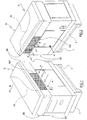
- the elements making up the quoted generator set are received in the bottom part of a generally parallelepiped insulated shell 6 with a rectangular plan (figs. 1, 2 and 4).
- the shell 6 is open at the bottom so as to be able to be slotted from above onto the platform 1, and be removably fixed there.
- the same shell 6 is equipped with a horizontal separator baffle 9 (figs. 3 and 4) that divides it into a bottom case 60 and a top chamber 66 communicating with each other, where the first 60 encloses the generator set and the second 66 acts as a passage for the respective flows of fresh air A and exhaust air B.
- a horizontal separator baffle 9 (figs. 3 and 4) that divides it into a bottom case 60 and a top chamber 66 communicating with each other, where the first 60 encloses the generator set and the second 66 acts as a passage for the respective flows of fresh air A and exhaust air B.
- a vertical dividing wall 10 consisting of sheets of metal plate and sound-absorbing panels is arranged, which in plan (fig. 4) has a sinuate extension developing substantially according to a diagonal of the shape in plan of said chamber 66.
- the chamber 66 is divided into two areas that in plan have substantially the shape of an elongated right-angled triangle extending generally parallel to the axis of the underlying engine 2 (fig. 4).
- One of said areas acts as a manifold for fresh air A, and the other area, in the bottom right of the same figure, acts as a manifold for exhaust air B.
- the manifold for fresh air A communicates with the area of the case 60 intended for the alternator 3 (fig. 3) through a generally trapezium-shaped horizontal opening 61 that is formed on the baffle 9 (fig. 4), and with the outside through a vertical window 161 equipped with a grate (fig. 1).
- Said horizontal opening 61 and said vertical window 161 are arranged in substantially opposite positions with respect to the longitudinal development of the manifold for fresh air A (fig. 3).
- the manifold for exhaust air B communicates with the area of the case 60 intended for the alternator 3 (fig. 3) through a rectangular-shaped horizontal opening 62 that is formed on the baffle 9 (fig. 4), and with the outside through a vertical window 162 equipped with a grate (figs. 2 and 3).
- Said horizontal opening 62 and the respective vertical window 162 are arranged in substantially opposite positions with respect to the longitudinal development of the manifold for exhaust air B (fig. 3).
- the fuel tank indicated with 20 in fig. 3, is removably arranged in a suitable side space formed on the platform 1.
Landscapes
- Engineering & Computer Science (AREA)
- Physics & Mathematics (AREA)
- Acoustics & Sound (AREA)
- Chemical & Material Sciences (AREA)
- Combustion & Propulsion (AREA)
- Mechanical Engineering (AREA)
- General Engineering & Computer Science (AREA)
- Exhaust Silencers (AREA)
Applications Claiming Priority (1)
| Application Number | Priority Date | Filing Date | Title |
|---|---|---|---|
| ITRE20040079 ITRE20040079A1 (it) | 2004-07-06 | 2004-07-06 | Gruppo elettrogeno perfezionato |
Publications (1)
| Publication Number | Publication Date |
|---|---|
| EP1614877A1 true EP1614877A1 (de) | 2006-01-11 |
Family
ID=35033752
Family Applications (1)
| Application Number | Title | Priority Date | Filing Date |
|---|---|---|---|
| EP05076370A Withdrawn EP1614877A1 (de) | 2004-07-06 | 2005-06-13 | Stromerzeuger |
Country Status (2)
| Country | Link |
|---|---|
| EP (1) | EP1614877A1 (de) |
| IT (1) | ITRE20040079A1 (de) |
Cited By (6)
| Publication number | Priority date | Publication date | Assignee | Title |
|---|---|---|---|---|
| US20110303482A1 (en) * | 2010-06-15 | 2011-12-15 | Aisin Seiki Kabushiki Kaisha | Outdoor power generating apparatus |
| CN104047713A (zh) * | 2013-03-16 | 2014-09-17 | 江苏普盛动力股份有限公司 | 用于单缸柴油机静音发电机组的散热系统 |
| CN104047712A (zh) * | 2013-03-14 | 2014-09-17 | 江苏普盛动力股份有限公司 | 单缸柴油机静音发电机组 |
| JP2015007374A (ja) * | 2013-06-24 | 2015-01-15 | デンヨー株式会社 | エンジン駆動型作業機 |
| CN105443239A (zh) * | 2015-12-24 | 2016-03-30 | 重庆安来动力机械有限公司 | 静音发电机组风道 |
| US10295600B2 (en) | 2013-06-18 | 2019-05-21 | Vlaamse Instelling Voor Technologisch Onderzoek Nv (Vito Nv) | Monitoring charge stored in a battery |
Citations (5)
| Publication number | Priority date | Publication date | Assignee | Title |
|---|---|---|---|---|
| JP2000213369A (ja) * | 1999-01-21 | 2000-08-02 | Meidensha Corp | 発電装置 |
| JP2002295265A (ja) * | 2001-03-28 | 2002-10-09 | Fuji Heavy Ind Ltd | 防音形エンジン発電機 |
| EP1296039A1 (de) * | 2001-09-25 | 2003-03-26 | Honda Giken Kogyo Kabushiki Kaisha | Motorgenerator |
| JP2003090223A (ja) * | 2001-07-10 | 2003-03-28 | Yanmar Co Ltd | 防音型発電装置 |
| US20030184094A1 (en) * | 2002-03-26 | 2003-10-02 | Sodemann Wesley C. | Removable fuel tank |
-
2004
- 2004-07-06 IT ITRE20040079 patent/ITRE20040079A1/it unknown
-
2005
- 2005-06-13 EP EP05076370A patent/EP1614877A1/de not_active Withdrawn
Patent Citations (5)
| Publication number | Priority date | Publication date | Assignee | Title |
|---|---|---|---|---|
| JP2000213369A (ja) * | 1999-01-21 | 2000-08-02 | Meidensha Corp | 発電装置 |
| JP2002295265A (ja) * | 2001-03-28 | 2002-10-09 | Fuji Heavy Ind Ltd | 防音形エンジン発電機 |
| JP2003090223A (ja) * | 2001-07-10 | 2003-03-28 | Yanmar Co Ltd | 防音型発電装置 |
| EP1296039A1 (de) * | 2001-09-25 | 2003-03-26 | Honda Giken Kogyo Kabushiki Kaisha | Motorgenerator |
| US20030184094A1 (en) * | 2002-03-26 | 2003-10-02 | Sodemann Wesley C. | Removable fuel tank |
Non-Patent Citations (3)
| Title |
|---|
| PATENT ABSTRACTS OF JAPAN vol. 2000, no. 11 3 January 2001 (2001-01-03) * |
| PATENT ABSTRACTS OF JAPAN vol. 2003, no. 02 5 February 2003 (2003-02-05) * |
| PATENT ABSTRACTS OF JAPAN vol. 2003, no. 07 3 July 2003 (2003-07-03) * |
Cited By (8)
| Publication number | Priority date | Publication date | Assignee | Title |
|---|---|---|---|---|
| US20110303482A1 (en) * | 2010-06-15 | 2011-12-15 | Aisin Seiki Kabushiki Kaisha | Outdoor power generating apparatus |
| EP2397667A3 (de) * | 2010-06-15 | 2012-08-22 | Aisin Seiki Kabushiki Kaisha | Außenstromerzeugungsvorrichtung |
| CN104047712A (zh) * | 2013-03-14 | 2014-09-17 | 江苏普盛动力股份有限公司 | 单缸柴油机静音发电机组 |
| CN104047713A (zh) * | 2013-03-16 | 2014-09-17 | 江苏普盛动力股份有限公司 | 用于单缸柴油机静音发电机组的散热系统 |
| US10295600B2 (en) | 2013-06-18 | 2019-05-21 | Vlaamse Instelling Voor Technologisch Onderzoek Nv (Vito Nv) | Monitoring charge stored in a battery |
| JP2015007374A (ja) * | 2013-06-24 | 2015-01-15 | デンヨー株式会社 | エンジン駆動型作業機 |
| CN105443239A (zh) * | 2015-12-24 | 2016-03-30 | 重庆安来动力机械有限公司 | 静音发电机组风道 |
| CN105443239B (zh) * | 2015-12-24 | 2017-10-20 | 重庆安来动力机械有限公司 | 静音发电机组风道 |
Also Published As
| Publication number | Publication date |
|---|---|
| ITRE20040079A1 (it) | 2004-10-06 |
Similar Documents
| Publication | Publication Date | Title |
|---|---|---|
| DE60200995T2 (de) | Motorgenerator | |
| DE60200266T2 (de) | Motorgenerator | |
| DE69831707T2 (de) | Brennkraftmaschinen getriebener Generator | |
| DE69906413T2 (de) | Brennkraftmotorgetriebene Arbeitsmaschine | |
| US6688424B1 (en) | Noise absorbing device and device for taking air into engine room of a construction machine | |
| DE3811131C2 (de) | Hublader mit einem schallgedämmten Antriebsaggregat | |
| DE69831706T2 (de) | Brennkraftmaschinen getriebener Generator | |
| JP3952972B2 (ja) | 建設機械の冷却装置 | |
| DE60007199T2 (de) | Batteriekühlleitung für Fahrzeug | |
| EP1614877A1 (de) | Stromerzeuger | |
| FR2891803B1 (fr) | Structure rigide pour mat d'accrochage de moteur d'aeronef, et mat comportant une telle structure | |
| US20140034403A1 (en) | Working machine | |
| DE102017000710B4 (de) | Einlassluftkühlvorrichtung für einen Motor | |
| DE112012004589T5 (de) | Küchenmaschine und deren Dampfkanalstruktur | |
| DE102014200190A1 (de) | Zylinderkopf | |
| DE69118713T2 (de) | Luftgekühlte Brennkraftmaschine | |
| DE102010011726A1 (de) | Zweitaktmotor und Motorgerät mit diesen Zweitaktmotor | |
| WO2010050481A1 (ja) | エンジン発電機 | |
| US20070054571A1 (en) | Watercraft | |
| DE19941863A1 (de) | Ansaugsystem für einen Verbrennungsmotor | |
| JP2011179165A (ja) | 作業機械 | |
| JP2739184B2 (ja) | 防音型エンジンの冷却装置 | |
| JPH084531A (ja) | 発電装置の冷却空気吸入構造 | |
| JP2014126036A (ja) | パッケージ収納型エンジン発電機 | |
| DE60028267T2 (de) | Brennkraftmaschine und ihre Benutzung |
Legal Events
| Date | Code | Title | Description |
|---|---|---|---|
| PUAI | Public reference made under article 153(3) epc to a published international application that has entered the european phase |
Free format text: ORIGINAL CODE: 0009012 |
|
| AK | Designated contracting states |
Kind code of ref document: A1 Designated state(s): AT BE BG CH CY CZ DE DK EE ES FI FR GB GR HU IE IS IT LI LT LU MC NL PL PT RO SE SI SK TR |
|
| AX | Request for extension of the european patent |
Extension state: AL BA HR LV MK YU |
|
| AKX | Designation fees paid | ||
| REG | Reference to a national code |
Ref country code: DE Ref legal event code: 8566 |
|
| STAA | Information on the status of an ep patent application or granted ep patent |
Free format text: STATUS: THE APPLICATION IS DEEMED TO BE WITHDRAWN |
|
| 18D | Application deemed to be withdrawn |
Effective date: 20060712 |