EP1614913A1 - Dispositif d'ouverture/fermeture de boite de dispositif et dispositif articule a 2 axes - Google Patents
Dispositif d'ouverture/fermeture de boite de dispositif et dispositif articule a 2 axes Download PDFInfo
- Publication number
- EP1614913A1 EP1614913A1 EP04725541A EP04725541A EP1614913A1 EP 1614913 A1 EP1614913 A1 EP 1614913A1 EP 04725541 A EP04725541 A EP 04725541A EP 04725541 A EP04725541 A EP 04725541A EP 1614913 A1 EP1614913 A1 EP 1614913A1
- Authority
- EP
- European Patent Office
- Prior art keywords
- turn
- turning
- turnable
- biasing
- main body
- Prior art date
- Legal status (The legal status is an assumption and is not a legal conclusion. Google has not performed a legal analysis and makes no representation as to the accuracy of the status listed.)
- Withdrawn
Links
Images








Classifications
-
- H—ELECTRICITY
- H04—ELECTRIC COMMUNICATION TECHNIQUE
- H04M—TELEPHONIC COMMUNICATION
- H04M1/00—Substation equipment, e.g. for use by subscribers
- H04M1/02—Constructional features of telephone sets
- H04M1/0202—Portable telephone sets, e.g. cordless phones, mobile phones or bar type handsets
- H04M1/0206—Portable telephones comprising a plurality of mechanically joined movable body parts, e.g. hinged housings
- H04M1/0208—Portable telephones comprising a plurality of mechanically joined movable body parts, e.g. hinged housings characterized by the relative motions of the body parts
- H04M1/0214—Foldable telephones, i.e. with body parts pivoting to an open position around an axis parallel to the plane they define in closed position
- H04M1/0216—Foldable in one direction, i.e. using a one degree of freedom hinge
- H04M1/022—The hinge comprising two parallel pivoting axes
-
- E—FIXED CONSTRUCTIONS
- E05—LOCKS; KEYS; WINDOW OR DOOR FITTINGS; SAFES
- E05D—HINGES OR SUSPENSION DEVICES FOR DOORS, WINDOWS OR WINGS
- E05D11/00—Additional features or accessories of hinges
- E05D11/10—Devices for preventing movement between relatively-movable hinge parts
- E05D11/1028—Devices for preventing movement between relatively-movable hinge parts for maintaining the hinge in two or more positions, e.g. intermediate or fully open
- E05D11/1078—Devices for preventing movement between relatively-movable hinge parts for maintaining the hinge in two or more positions, e.g. intermediate or fully open the maintaining means acting parallel to the pivot
-
- E—FIXED CONSTRUCTIONS
- E05—LOCKS; KEYS; WINDOW OR DOOR FITTINGS; SAFES
- E05D—HINGES OR SUSPENSION DEVICES FOR DOORS, WINDOWS OR WINGS
- E05D3/00—Hinges with pins
- E05D3/06—Hinges with pins with two or more pins
- E05D3/12—Hinges with pins with two or more pins with two parallel pins and one arm
-
- E—FIXED CONSTRUCTIONS
- E05—LOCKS; KEYS; WINDOW OR DOOR FITTINGS; SAFES
- E05Y—INDEXING SCHEME ASSOCIATED WITH SUBCLASSES E05D AND E05F, RELATING TO CONSTRUCTION ELEMENTS, ELECTRIC CONTROL, POWER SUPPLY, POWER SIGNAL OR TRANSMISSION, USER INTERFACES, MOUNTING OR COUPLING, DETAILS, ACCESSORIES, AUXILIARY OPERATIONS NOT OTHERWISE PROVIDED FOR, APPLICATION THEREOF
- E05Y2999/00—Subject-matter not otherwise provided for in this subclass
Definitions
- This invention relates to an opening/closing apparatus for turnably connecting first and second two equipment parts such as a transmission case and a reception case of a portable cellular telephone set, or a main body case with input keys provided thereon and a display case with a liquid crystal display provided thereon of a notebook type personal computer.
- the invention also relates to a two-axis hinge apparatus suitably used for such opening/closing apparatus.
- an opening/closing apparatus for an equipment case in which a transmission case and a reception case for a portable cellular telephone set are turnably connected to each other through a two-axis hinge apparatus.
- a transmission case is turnably connected to one end part of a hinge main body of a two-axis hinge apparatus through a first hinge shaft
- a reception case is turnably connected to the other end part of the hinge main body through a second hinge shaft. Owing to this arrangement, the reception case and the transmission case are turnably connected to each other through an opening/closing apparatus.
- an opening/closing apparatus for an equipment case comprising a first case, a hinge apparatus having a hinge main body whose one end part is turnably connected to the first case about a first turning axis, and a second case turnably connected to the other end part of the hinge main body about a second turning axis parallel to the first turning axis, the hinge main body being turned with respect to the first case and the second case being turned with respect to the hinge main body thereby the second case being turnable with respect to the first case between a folding position and a developing position, wherein between the first case and the hinge main body, there are provided a first stop means adapted to stop the hinge main body in a predetermined initial position when the hinge main body is turned to the predetermined initial position in one direction so that the second case is turned toward the folding position from the developing position, a second stop means adapted to stop the hinge main body in a predetermined terminal position when the hinge main body is turned to the predetermined terminal position in the other direction so that
- the first turn prohibition means is a first turn biasing means adapted to turn bias the hinge main body in the one direction when the hinge main body is located in the initial position
- the second turn prohibition means is a second turn biasing means adapted to turn bias the hinge main body in the other direction when the hinge main body is located in the terminal position
- the third turn prohibition means is a third turn biasing means adapted to turn bias the second case in the closing direction when the second case is located in the folding position
- the fourth prohibition means is a fourth turn biasing means adapted to turn bias the second case in the opening direction when the second case is located in the intermediate position.
- the hinge apparatus includes a first hinge for turnably connecting the first case and one end part of the hinge main body together about the first turning axis, and a second hinge for turnably connecting the second case and the other end part of the hinge main body together about the second turning axis
- the first hinge includes a first movable member disposed at one of the first case and the hinge main body such that the first movable member is non-turnable but movable in the direction of the first turning axis, and a first biasing means adapted to bias the first movable member toward the other of the first case and the hinge main body, between confronting surfaces of the first movable member and the other of the first case and the hinge main body, there are provided a first conversion means adapted to convert the biasing force of the first biasing means acting on the first movable member when the hinge main body is located in the initial position, into a turn biasing force for turn biasing the hinge main body in the one direction, and a second conversion means adapted to convert the biasing force of the first biasing
- the folding position may be restricted by abutment of the second case with the first case.
- the intermediate position is defined such that when the second case is located in the intermediate position, the second case is located on a line orthogonal to the first and second turning axes.
- a two-axis hinge apparatus comprising a hinge main body, a first hinge disposed on the hinge main body with an axis thereof aligned with a first turning axis, and a second hinge disposed on the hinge main body with an axis thereof aligned with a second turning axis parallel to the first turning axis
- the first hinge includes a first fixing member non-turnably disposed on the hinge main body and a first turnable member connected to the first fixing member such that the first turnable member is turnable between a first initial position and a first turning position, between the first fixing member and the first turnable member
- a first turn prohibition means which is adapted to prohibit the first turnable member from turning toward the fist turning position from the first initial position with a predetermined force
- a second turn prohibition means which is adapted to prohibit the first turnable member from turning toward the first initial position from the first turning position with a predetermined force
- a first stop means which is adapted to
- the first hinge further includes a first movable member disposed between the first fixing member and the first turnable member and connected to the first fixing member such that the first movable member is non-turnable but movable in the direction of the first turning axis, and a first biasing means adapted to bias the first movable member toward the first turnable member along the first turning axis, between confronting surfaces of the first turnable member and the first movable member, there are provided a first conversion means adapted to convert a biasing force of the first biasing means acting on the first movable member when the first turnable member is located in the first initial position, into a turn biasing force for turn biasing the first turnable member toward the first initial position from the first turnable position, a second conversion means adapted to convert a biasing force of the first biasing means acting on the first movable member when the first turnable member is located in the first turnable position, into a turn biasing force for turn biasing the first turnable member
- a two-axis hinge apparatus comprising a hinge main body, a first hinge disposed on the hinge main body with an axis thereof aligned with a first turning axis, and a second hinge disposed on the hinge main body with an axis thereof aligned with a second turning axis parallel to the first turning axis
- the first hinge includes a first fixing member non-turnably disposed on the hinge main body and a first turnable member connected to the first fixing member such that the first turnable member is turnable between a first initial position and a first turning position, between the first fixing member and the first turnable member
- a first turn prohibition means which is adapted to prohibit the first turnable member from turning toward the first turning position from the first initial position with a predetermined force
- a second turn prohibition means which is adapted to prohibit the first turnable member from turning toward the first initial position from the first turning position with a predetermined force
- a first stop means which is adapted to stop the first
- the first hinge further includes a first movable member disposed between the first fixing member and the first turnable member and connected to the first fixing member such that the first movable member is non-turnable but movable in the direction of the first turning axis, and a first biasing means adapted to bias the first movable member toward the first turnable member along the first turning axis, between confronting surfaces of the first turnable member and the first movable member, there are provided a first conversion means adapted to convert a biasing force of the first biasing means acting on the first movable member when the first turnable member is located in the first initial position, into a turn biasing force for turn biasing the first turnable member toward the first initial position from the first turning position, a second conversion means adapted to convert a biasing force of the first biasing means acting on the first movable member when the first turnable member is located in the first turning position, into a turn biasing force for turn biasing the first turnable member toward the
- a two-axis hinge apparatus comprising a hinge main body, a first hinge disposed on the hinge main body with an axis thereof aligned with a first turning axis, and a second hinge disposed on the hinge main body with an axis thereof aligned with a second turning axis parallel to the first turning axis
- the first hinge includes a first fixing member non-turnably disposed on the hinge main body and a first turnable member connected to the first fixing member such that the first turnable member is turnable between the first initial position and the first turning position, between the first fixing member and the first turnable member
- a first turn prohibition means which is adapted to prohibit the first turnable member from turning toward the first turning position from the first initial position with a predetermined force
- a second turn prohibition means which is adapted to prohibit the first turnable member from turning toward the first initial position from the first turning position with a predetermined force
- the second hinge includes a second fixing member non-turnably disposed
- the first fixing member further includes a first movable member disposed between the first fixing member and the first turnable member and connected to the first fixing member such that the first movable member is non-turnable but movable in the direction of the first turning axis, and a first biasing member adapted to bias the first movable member toward the first turnable member along the first turning axis, between confronting surfaces of the first turnable member and the first movable member, there are provided a first conversion means adapted to convert a biasing force of the first biasing means acting on the first movable member when the first turnable member is located in the first initial position, into a turn biasing force for turn biasing the first turnable member toward the first initial position from the first turning position, and a second conversion means adapted to convert a biasing force of the first biasing means acting on the first movable member when the first movable member is located in the first turning position, into a turn biasing force for turn biasing the first turnable
- a two-axis hinge apparatus comprising a hinge main body, a first hinge disposed on the hinge main body with an axis thereof aligned with a first turning axis, and a second hinge disposed on the hinge main body with an axis thereof aligned with a second turning axis parallel to the first turning axis
- the first hinge includes a first fixing member non-turnably disposed on the hinge main body and a first turnable member connected to the first fixing member such that the first turnable member is turnable between a first initial position and a first turning position, between the first fixing member and the first turnable member
- a first turn prohibition means which is adapted to prohibit the first turnable member from turning toward the first turning position from the first initial position with a predetermined force
- a second turn prohibition means which is adapted to prohibit the first turnable member from turning toward the first initial position from the first turning position with a predetermined force
- a second stop means which is adapted to stop the first turn prohibition means which is adapted to prohibit the first turnable member
- the first hinge further includes a first movable member disposed between the first fixing member and the first turnable member and connected to the first fixing member such that the first movable member is non-turnable but movable in the direction of the first turning axis, and a first biasing means adapted to bias the first movable member toward the first turnable member along the first turning axis, between confronting surfaces of the first turnable member and the first movable member, there are provided a first conversion means adapted to convert a biasing force of the first biasing means acting on the first movable member when the first turnable member is located in the first initial position, into a turn biasing force for turn biasing the first turnable member toward the first initial position from the first turning position, a second conversion means adapted to convert a biasing force of the first biasing means acting on the first movable member when the first turnable member is located in the first turning position, into a turn biasing force for turn biasing the first turnable member toward the
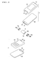
- FIGS. 1 through 16 show a first embodiment according to a first mode of the present invention.
- an opening/closing apparatus for an equipment case according to the present invention is applied to a portable cellular telephone set.
- the portable cellular telephone set 1 includes a transmission case (first case) 2 provided with a transmission section, and a reception case (second case) 3 provided with a reception section.
- the reception case 3 is turnably connected to the transmission case 2 through a hinge apparatus 4.
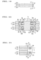
- the reception case 3 is turnable between a folding position shown in FIGS. 1(A) and 5 and a transmission position (developing position) shown in FIGS. 1(C) and 7.
- the folding position is restricted by abutment of the front surface 3a of the reception case 3 with the front surface 2a of the transmission case 2.
- the turn angle of the reception case 3 with respect to the transmission case 2 is zero (0) degree.
- the transmission position is a position attainable when the reception case 3 is turned maximum with respect to the transmission case 2.
- the transmission position is set to a position 160 degrees away from the folding position.
- the transmission position as later described, is restricted by abutment of a hinge main body 5 of the hinge apparatus 4 with a second abutment surface 25 of the transmission case 2 and by abutment of a third abutment surface 34 of the reception case 3 with the hinge main body 6. As shown in FIGS.
- an intermediate position is set to a position attainable when the reception case 3 is turned by a predetermined angle (one hundred (100) degrees in this embodiment) from the folding position toward the transmission position.
- the intermediate position as later described, is restricted by abutment of the third abutment surface 34 with the hinge main body 5.
- the transmission case 2 and the reception case 3 are turnable relative to each other.
- the description to follow will be made on the assumption that transmission case 2 is fixed in position and the reception case 3 is turned relative to the transmission case 2.
- the transmission case 2 includes an upper half body 2A which is brought into abutment with the reception case 3 when the reception case 3 is turned to the folding position, and a lower case half body 2B fixed to under the upper case half body 2A in a superimposed manner.
- the case half bodies 2A, 2B each have a thin rectangular parallelepiped contour.
- a recess 21 is formed in one end part in the longitudinal direction of the confronting surface with the upper case half body 2A of the lower case half body 2B.
- a cutout part 22 is formed in one end part in the longitudinal direction of the upper case half body 2A confronting this recess 21.
- Constituted by the cutout part 22 and the recess 21 is a receiving recess 23 whose longitudinal direction is directed in the short direction of the transmission case 2 and which is formed at one end part in the longitudinal direction of the transmission case 2,
- the reception case 3 includes a lower case half body 3A which is brought into abutment with the transmission case 2 when the reception case 3 is turned to the folding position, and an upper case half body 3B fixed to above the lower case half body 3A in a superimposed manner.
- the case half bodies 3A, 3B each have a thin rectangular parallelepiped contour.
- a recess 31 is formed in one end part in the longitudinal direction of the confronting surface with the upper case half body 3A of the upper case half body 3B.
- a cutout part 32 is formed in one end part in the longitudinal direction of the lower case half body 3A confronting the recess 31.
- a receiving recess 33 whose longitudinal direction is directed in the short direction of the reception case 3 is constituted in one end part in the longitudinal direction of the reception case 3.
- the receiving recess 33 is arranged in parallel with the receiving recess 23.
- the transmission case 2 and the reception case 3 are turnably connected to each other through the hinge apparatus 4.
- the hinge apparatus 4 includes a hinge main body 5.
- the hinge main body 5 has a thin rectangular parallelepiped contour and is arranged such that the longitudinal direction of the hinge main body 5 is directed in the same direction as the longitudinal direction of the receiving recesses 23, 33.
- One and the other end parts in the short direction of the hinge main body 5 are turnably inserted in the receiving recesses 23, 33, respectively.
- One end part in the short direction of the hinge main body 5 is turnably connected to the transmission case 2 through a pair of first hinges 6A, 6B which are arranged at opposite end parts in the longitudinal direction of the hinge main body 5 about a first turning axis L1 (see FIG. 4).
- the other end part in the short direction of the hinge main body 5 is turnably connected to the reception case 3 through second hinges 7A, 7B which are arranged at opposite end parts in the longitudinal direction of the hinge main body 5 about a second turning axis L2 (see FIG. 4).
- Only one each of the first hinges 6A, 6B and the second hinges 7A, 7B may be used, and a hinge shaft may be used for the other of the first hinge 6A,6B and the second hinge 7A,7B.
- the first and second turning axes L1, L2 are parallel to each other and also parallel to the longitudinal direction of the receiving recesses 23, 33. Moreover, when the hinge main body 5 is located in an initial position as later described, the second turning axis L2, as described in FIGS. 3 and 4, is offset to the other end of the reception case 3 with respect to the first turning axis L1. Owing to this arrangement, when the reception case 3 is turned to the intermediate position, the reception case 3 is located on the line orthogonal to the first and second turning axes L1, L2. Particularly, in this embodiment, the abutting surface between the case half bodies 3A, 3B is located on the line orthogonal to the first and second axes.
- the first and second turning axes L1, L2 may be arranged in the same position in the longitudinal direction of the cases 2, 3, or they may be offset in the reverse direction in contrast with the case shown in FIG. 3.
- the hinge main body 5 is turnable between the initial position shown in FIGS. 5 and 6 and the terminal position shown in FIG. 7 about the first turning axis L1 with respect to the transmission case 2.
- the initial position is, as shown in FIGS. 5 and 6, restricted by abutment of the hinge main body 5 with a first abutment surface (first stop means) 24 which is constituted by only a wall surface extending in the short direction of the case 2 of the entire wall surface defming the cutout part 22.
- the terminal position is, as shown in FIG.
- second stop means 25 which is formed on a part existing between the recess 21 and the lower case half body 2b of the entire upper surface (confronting surface with respect to the upper case half body 2A) of the lower case half body 2B.
- the reception case 3 is turnable between a second initial position shown in FIG. 5 and a second terminal position shown in FIG. 6 with respect to the hinge main body 5 which is located in the initial position.
- the second initial position is restricted by abutment of the front surface 3a of the reception case 3 with the front surface 2a of the transmission case 2.
- the second terminal position is, as shown in FIG. 6, restricted by abutment of a third abutment surface (third stop means) 34 which is formed on a part existing between the recess 31 and one end edge of the upper case half body 3B of the entire lower surface (confronting surface with the lower case half body 3A) of the upper case half body 3B with the hinge main body 5.
- the second initial position and the second terminal position of the reception case 3 are in the same positions as the folding position and the intermediate position, respectively.
- the reception case 3 is turned with respect to the main body 5 and so, the second initial position and the second terminal position of the reception case 3 are in the same positions as the folding position and the intermediate position, respectively.
- the second initial position is also referred to as the folding position and the second terminal position is also referred to as the intermediate position.
- the folding position as one limit position in the turnable extent with respect to the hinge main body 5 of the reception case 3 may be restricted by abutment, for example, of the wall surface 32a extending in the short direction of the case 3 of the entire wall surface which defines the cutout part 32 instead of by abutment of the reception case 3 with the transmission case 2.
- abutment for example, of the wall surface 32a extending in the short direction of the case 3 of the entire wall surface which defines the cutout part 32 instead of by abutment of the reception case 3 with the transmission case 2.
- turn of the hinge main body 5 with respect to the transmission case 2 and turn of the reception case 3 with respect to the hinge main body 5 are made in predetermined order respectively under the effect of the first hinges 6A, 6B and the second hinges 7A, 7B of the hinge apparatus 4, and under the effect of the first through third abutment surfaces 24, 25, 34.
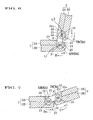
- the hinge main body 5 is located in the initial position and the reception case 3 is located in the folding position, as shown in FIG. 5.
- the reception case 3 is turned toward the transmission position
- the reception case 3 is turned in the direction as indicated by an arrow D (opening direction) in FIGS. 5 through 7 about the second turning axis L2 with respect to the hinge main body 5.
- the hinge main body 5 maintains its stopping state until the reception case 3 reaches the intermediate position.
- the third abutment surface 34 is brought into abutment with the hinge main body 5 as shown in FIG. 6.
- the hinge main body 5 begins to turn from the initial position toward the terminal position in the direction as indicated by an arrow B (one direction) with respect to the transmission case 2. Then, as shown in FIG. 7, when the hinge main body 5 is turned to the terminal position in the direction as indicated by the arrow B, the hinge main body 5 is abutted with the second abutment surface 25 and stopped, and thus, the reception case 3 is also stopped. At that time, the reception case 3 already turns with respect to the transmission case 2 by a portion equivalent to the sum of its own turn from the folding position to the intermediate position and the turn of the hinge main body 5 from the initial position to the terminal position and already reaches the transmission position.
- the reception case 3 In case the reception case 3 is to be turned from the transmission position to the folding position, the reception case 3 is pushed in the direction as indicated by an arrow C (closing direction). Then, the hinge main body 5 is turned from the terminal position toward the initial position in the direction as indicated by an arrow A (the other direction) about the first turning axis L1 with respect to the transmission case 2. At that time, the reception case 3 is not turned with respect to the hinge main body 5 but it is turned about the first turning axis L1 in unison with the hinge body 5. Accordingly, when the hinge main body 5 reaches the initial position shown in FIG. 6, the reception case 3 reaches the intermediate position. When the hinge main body 5 reaches the initial position, it is abutted with the first abutment surface 24.
- the hinge main body 5 is stopped. Thereafter, when the reception case 3 is pushed further toward the folding position from the intermediate position in a direction as indicated by the arrow C, the reception case 3 is turned in the direction as indicated by the arrow C about the second turning axis L2 with respect to the hinge main body 5 because the hinge main body 5 is stopped. When the reception case 3 is turned into the folding position, it is abutted with the transmission case 2 and stopped.
- first hinges 6A, 6B and second hinges 7A, 7B will be described which coact with the first through third abutment surfaces 24, 25, 34 to turn the reception case 3 and the hinge main body 5 in the above-mentioned order.
- the first hinges 6A, 6B are laterally symmetrically constituted, and the second hinges 7A, 7B are also laterally symmetrically constituted.
- the first hinge 6A and the second hinge 7A are same in basic constitution only excepting a part of constitution. So, the first hinge 6A will be described first and then, the second hinge 7A will be described only on those points which are different from the first hinge 6A. Description of the first hinge 6B and the second hinge 7B is omitted.
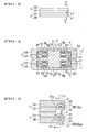
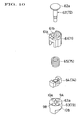
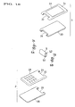
- the first hinge 6A includes a first fixing member 61, a first hinge shaft 62, a first turnable member 63, a first movable member 64 and a first coiled spring (first biasing means) 65.
- the first fixing member 61 has a circular cylindrical configuration and includes a bottom part 61a at one end part thereof. Through-hole 61b is formed in a central part of the bottom part 61a.
- the first hinge shaft 62 is turnably passed through this through-hole 61b.
- a head part 62a is formed on one end part of the first hinge shaft 62. Abutment of the bottom part 61a with this head part 62a prohibits the first fixing member 61 from escaping through one end part of the fist hinge shaft 62.
- the first turnable member 63 has a solid short circular columnar configuration and is arranged in opposing relation to the first fixing member 61. On the axis of the first turnable member 63, a reduced-diameter hole part 63a is formed in the end part on the first fixing member 61 side and an enlarged-diameter hole part 63b is formed in the reverse side end part. The other end part of the first hinge shaft 62 is non-turnably press-fitted in the reduced-diameter hole part 63a. Owing to this arrangement, the first turnable member 63 is turnably connected to the first fixing member 61 through the first hinge shaft 62.
- the first turnable member 63 may be designed in such a manner as to be able to turn with respect to the first hinge shaft 62.
- the first fixing member 61 may be designed in such a manner as to be non-turnable with respect to the first hinge shaft 62.
- the other end part of the first hinge shaft 62 is passed through the reduced-diameter hole part 63a and allowed to project slightly toward the enlarged-diameter hole part 63b. By caulking this projected part of the first hinge shaft 62 in the manner as by an imaginary line in FIG. 9, the first turnable member 63 is prohibited from escaping through the other end part of the first hinge shaft 62.
- the first movable member 64 is fitted to the central part of the first hinge shaft 62 located between the first fixing member 61 and the second turnable member 63 in such a manner as to be turnable, and slideable in the axial direction of the first hinge shaft 62.
- the first movable member 64 is connected to the first fixing member 61 in such a manner as to be non-turnable, but movable in the axial direction of the first hinge shaft 62.
- the first coiled spring 65 is arranged between the first movable member 64 and the bottom part 61a of the first fixing member 61. By this coiled spring 65, the first movable member 64 is biased toward the first turnable member 63.
- the first hinge 6A is arranged with its axis aligned with the first turning axis L1.
- the first fixing member 61 is non-turnably fitted to a support hole 51 which is formed on an end face of the hinge main body 5 with its axis aligned with the first turning axis L1.
- One end part of the first turnable member 63 is non-turnably fitted to a support hole 26 formed on the first turning axis L1 of the transmission case 2 and the other end part is turnably fitted to the support hole 51.
- the transmission case 2 and the hinge main body 5 are turnably connected to each other through the first hinge 6A, and particularly about the first turning axis L1.
- the first fixing member 61 and the first movable member 64 are turned in unison with respect to the transmission case 2 and the first turnable member 63.
- a pair of spherical bodies 8A, 8B are fixedly embedded in the confronting surface with the first turnable member 63 of the first movable member 64 with their respective one parts projected toward the second turnable member 63.
- the pair of spherical bodies 8A, 8B are symmetrically arranged with respect to the first turning axis L1. That is, the pair of spherical bodies 8A, 8B are arranged on a circumference about the first turning axis L1 in such a manner as to be 180 degrees away from each other in the peripheral direction.
- the pair of spherical bodies 8A, 8B are pushed against the confronting surface with the first movable member 64 of the first turnable member 63 by the first coiled spring 65.
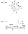
- a pair of recesses 9A, 9B and another pair of recesses 10A, 10B are, as shown in FIG. 11, formed on the confronting surface with the first movable member 64 of the first turnable member 63.
- the recesses 9A, 9B; 10A, 10B are arranged on the same circumference as the circumference on which the spherical bodies 8A, 8B are arranged.
- the pair of recesses 9A, 9B are arranged 180 degrees away from each other in the peripheral direction, and the other pair of recesses 10A, 10B are also arranged 180 degrees away from each other in the peripheral direction.
- the pair of recesses 9A, 9B and the other pair of recesses 10A, 10B are arranged in such a manner as to have the following relation with the spherical bodies 8A, 8B. That is, the pair of recesses 9A, 9B are arranged such that when the hinge main body 5 is turned to an initial nearby position which is located before the initial position by a predetermined angle (for example, 10 to 15 degrees) in case the hinge main body 5 is turned toward the initial position from the terminal position in the direction as indicated by an arrow A of FIG. 5 and in associate therewith, the spherical bodies 8A, 8B are turned in the direction as indicated by an arrow A of FIG.
- a predetermined angle for example, 10 to 15 degrees
- the spherical bodies 8A, 8B begin to enter the pair of recesses 9A, 9B, respectively, and the spherical bodies 8A, 8B are press contacted respectively with inclination surfaces 91, 91 (see FIG. 12) which are formed in the respective bottom surfaces of the recesses 9A, 9B.
- the pair of recesses 9A, 9B are arranged such that the spherical bodies 8A, 8B are slidingly moved on the inclination surfaces 91, 91 in the peripheral direction toward the centers of the recesses 9A, 9B until the hinge main body 5 reaches the initial position from the initial nearby position.
- the biasing force of the first coiled spring 65 is converted to a turn biasing force about the first turning axis L1 by the inclination surfaces 91, 91 and also by the spherical bodies 8A, 8B which are in contact with the inclinations surfaces 91, 91.
- the spherical bodies 8A, 8B are turn biased in the direction as indicated by the arrow A of FIG. 11 and the hinge main body 5 is turn biased in the direction as indicated by the arrow A of FIGS. 5 through 7.
- a first conversion means 11 adapted to convert the biasing force of the first coiled spring 65 into the turn biasing force is constituted by the inclination surfaces 91, 91 and the spherical bodies 8A, 8B
- a first turn biasing means (first turn prohibition means) 12 adapted to turn bias the hinge main body 5 toward the terminal position from the initial position is constituted by the first conversion means 11 and the first coiled spring 65.
- the first turn biasing means 12 is adapted to prohibit the hinge main body 5 from turning toward the terminal position from the initial position.
- the pair of recesses 10A, 10B are arranged such that when the hinge main body 5 is turned to a terminal nearby position which is located before the terminal position by a predetermined angle (for example, 10 to 15 degrees) in case the hinge main body 5 is turned toward the terminal position from the initial position in the direction as indicated by the arrow B of FIG. 7 and in accompany therewith, the spherical bodies 8A, 8B are turned in the direction as indicated by the arrow B of FIG, 11 with respect to the first turnable member 63, the spherical bodies 8A, 8B begin to enter the pair of recesses 10A, 10B, respectively.
- a predetermined angle for example, 10 to 15 degrees
- the spherical bodies 8A, 8B entered the recesses 10A, 10B are press contacted respectively with inclination surfaces 101, 101 which are formed in the respective bottom surfaces of the recesses 10A, 10B as shown in FIG. 12.
- the pair of recesses 10A, 10B are arranged such that the spherical bodies 8A, 8B are slidingly moved on the inclination surfaces 101, 101 in the peripheral direction toward the centers of the recesses 10A, 10B until the hinge main body 5 reaches the terminal position from the terminal nearby position.
- the biasing force of the first coiled spring 65 is converted to a turn biasing force about the first turning axis L1 by the inclination surfaces 101, 101 and also by the spherical bodies 8A, 8B which are in contact with the inclinations surfaces 101, 101.
- the spherical bodies 8A, 8B are turn biased in the direction as indicated by the arrow B of FIG. 11 and the hinge main body 5 is turn biased in the direction ad indicated by the arrow B of FIGS. 5 through 7.
- a second conversion means 13 adapted to convert the biasing force of the first coiled spring 65 into the turn biasing force is constituted by the inclination surfaces 101, 101 and the spherical bodies 8A, 8B
- a second turn biasing means (second turn prohibition means) 14 adapted to turn bias the hinge main body 5 toward the terminal position from the initial position is constituted by the second conversion means 13 and the first coiled spring 65.
- the second turn biasing means 14 is adapted to prohibit the hinge main body 5 from turning toward the initial position from the terminal position.
- the second hinge 7A includes, as shown in FIGS. 9 and 10, a second fixing member 71, a second hinge shaft 62, a second turnable member 73, a second movable member 74 and a second coiled spring (second biasing means) as component members corresponding respectively to the first fixing member 61, the first hinge shaft 62, the first turnable member 63, the first movable member 64 and the first coiled spring 65 of the first hinge 6A.
- the second hinge 7A is arranged with the axis of the second hinge shaft 72 aligned with a second turning axis L2.
- the second fixing member 71 is non-turnably fitted to a support hole 52 which is formed on an end face of the hinge main body 5 such that the axis of the support hole 52 is aligned with the second turning axis.
- the second turnable member 73 is non-turnably fitted at one end part thereof to a support hole 37 which is formed on the second turning axis L2 of the reception case 3 and turnably fitted at the other end part to the support hole 52.
- the reception case 3 is turnably connected to the hinge main body 5 through the second hinge 7A such that said reception case 3 is turnable about the second turning axis L2.
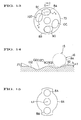
- recesses 9A, 9B; 10A, 10B recesses 9C, 9D; 10C, 10D are formed on the confronting surface of the second turnable member 73 with respect to the second movable member 74, as shown in FIG. 13.
- the recesses 9C, 9D; 10C, 10D are different in arrangement in the peripheral direction from the 9A, 9B; 10A, 10B.
- one pair of recesses 9C, 9D are arranged such that when the reception case 3 is turned to a folding nearby position which is located before the folding position by a predetermined angle (for example, 10 to 15 degrees) in case the reception case 3 is turned toward the folding position from the intermediate position in the direction as indicated by the arrow C of FIGS. 5 through 7 (at that time, the hinge main body 5 is stopped in the initial position), the spherical bodies 8A, 8B are entered respectively into the recesses 9C, 9D.
- the spherical bodies 8A, 8B entered respectively into the recesses 9C, 9D are press contacted respectively with inclination surfaces 92, 92 which are formed on the bottom surfaces of the recesses 9C, 9D, as shown in FIG.
- the one pair of recesses 9C, 9D are arranged such that the spherical bodies 8A, 8B are slidingly moved on the inclination surfaces 92, 92 toward the centers of the recesses 9C, 9D in the peripheral direction until the reception case 3 reaches the folding position from the folding nearby position.
- the biasing force of the second coiled spring 75 is converted into a turn biasing force about the second turning axis L2 by the inclination surfaces 92, 92 and by the spherical bodies 8A, 8B which are in contact with the inclination surfaces 92, 92.
- the second turnable member 73 is turn biased in the direction as indicated by the arrow C of FIG. 13 and thus, the reception case 3 is turn biased in the direction as indicated by the arrow C of FIGS. 5 through 7.
- the reception case 3 when located between the folding position and the folding nearby position, the reception case 3 is automatically turned to the folding position by the turn biasing force of the second coiled spring 75 which has been converted by the inclination surfaces 92, 92 and by the spherical bodies 8A, 8B, and held in that folding position.
- a third conversion means 15 adapted to convert the biasing force of the second coiled spring 75 into a turn biasing force is constituted by the inclination surfaces 92, 92 and the spherical bodies 8A, 8B, and a third turn biasing means (third turn prohibition means) 16 adapted to turn bias the reception case 3 toward the folding position from the intermediate position through the third conversion means 15 and the second coiled spring 75.
- the third turn biasing means 16 prohibits the reception case 3 from turning toward the transmission position (developing position) by its turn biasing force.
- the other pair of recesses 10C, 10D are arranged such that when the reception case 3 is turned to an intermediate nearby position which is located before the intermediate position by a predetermined angle (for example, 10 to 15 degrees) in case the reception 3 is turned toward the intermediate position from the folding position in the direction as indicated by the arrow D of FIGS. 5 through 7 (at that time, the hinge main body 5 is stopped in the initial position), the spherical bodies 10C, 10D are entered into the recesses 10C, 10D, respectively.
- the spherical bodies 8A, 8B entered into the recesses 10C, 10D are press contacted respectively with inclination surfaces 102, 102 which are formed on the bottom surfaces of the recesses 10C, 10D, as shown in FIG. 14.
- the one pair of recesses 10C, 10D are arranged such that the spherical bodies 8A, 8B are slidingly moved on the inclination surfaces 102, 102 toward the centers of the recesses 10C, 10D in the peripheral direction until the reception case 3 reaches the intermediate position from the intermediate nearly position.
- the biasing force of the second coiled spring 75 is converted into a turn biasing force about the second turning axis L2 by the inclination surfaces 102, 102 and by the spherical bodies 8A, 8B which are in contact with the inclination surfaces 102, 102.
- the second turnable member 73 is turn biased in the direction as indicated by the arrow D of FIG. 13 and thus, the reception case 3 is turn biased in the direction as indicated by the arrow D of FIGS. 5 through 7.
- the reception case 3 is automatically turned to the intermediate position by the turn biasing force of the second coiled spring 75 which has been converted by the inclination surfaces 101, 102 and the spherical bodies 8A, 8B and held in that intermediate position.
- a fourth conversion means 17 adapted to convert the biasing force of the second coiled spring 75 into a turn biasing force is constituted by the inclination surfaces 102, 102 and the spherical bodies 8A, 8B
- a fourth turn biasing means (fourth turn prohibition means) 18 adapted to turn bias the reception case 3 toward the intermediate position from the folding position is constituted by the fourth conversion means 17 and the second coiled spring 75.
- the fourth turn prohibition means 18 prohibits the reception case 3 from turning toward the folding position from the intermediate position by its turn biasing force.
- the angles of inclination of the inclination surfaces 91, 101 with respect to a plane orthogonal to the first turning axis L1 are, as shown in FIG. 12, set to be angles ⁇ 1 and ⁇ 1, respectively.
- the angles of inclination of the inclination surfaces 92, 102 with respect to a plane orthogonal to the second turning axis L2 are, as shown in FIG. 14, set to be angles ⁇ 2 and ⁇ 2, respectively.
- the angle ⁇ 1 is set to be larger than the angle ⁇ 2
- the angle ⁇ 2 is set to be larger than ⁇ 1.
- the turn biasing force of the first turn biasing means 12 is set to be larger than the turn biasing force of the third turn biasing means 16 and the turn biasing force of the fourth turn biasing means 18 is set to be larger than the turn biasing force of the second turn biasing means 14.
- the relation of size between the angle ⁇ 1 and the angle ⁇ 2 and the relation of size between the angle ⁇ 2 and the angle ⁇ 1 may be optionally set as long as the turn biasing force of the fourth turn biasing means 18 is set to be larger than the turn biasing force of the second turn biasing means 14.
- the hinge main body 5 is located in the initial position and the reception case 3 is located in the folding position.
- the spherical bodies 8A, 8B of the first hinge 6A are entered in the recesses 9A, 9B, respectively and the spherical bodies 8A, 8B of the second hinge 7A are entered in the recesses 9C, 9D, respectively.
- the hinge main body 5 When it is attempted to turn the reception case 3 toward the transmission position, the hinge main body 5 is held in the stopped state in the initial position because the turn biasing force of the first turn biasing means 12 is larger than the turn biasing force of the third turn biasing means 16, and the reception case 3 is turned first in the direction of the arrow D of FIG. 5 about the second turning axis L2. That is, the reception case 3 is turned toward the intermediate position with respect to the hinge main body 5. During the time the reception case 3 is turned from the folding position to the folding nearby position, the reception case 3 is turned against the turn biasing force of the third turn biasing means 16.
- the reception case 3 When the reception case 3 is located between the folding nearby position and the intermediate nearby position, the spherical bodies 8A, 8B are slidingly moved on the confronting surface of the second turnable member 73 with respect to the second movable member 74 and a frictional resistance is generated therebetween. Therefore, the reception case 3 is turned against the frictional resistance. Of course, since this frictional resistance is smaller than the turn biasing force of the first turn biasing means 12, the hinge main body 5 is held in its stopped state in the initial position.
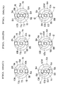
- the reception case 3 When the reception case 3 reaches the intermediate nearby position, as shown in FIG. 16(B), the spherical bodies 8A, 8B of the second hinge 7A are press contacted with the inclination surfaces 102, 102 of the recesses 10C, 10D, respectively and as a result, the reception case 3 is automatically turned to the intermediate position by the turn biasing force of the fourth turn biasing means 18.
- the third abutment surface 34 is abutted with the hinge main body as shown in FIG. 6. This makes it impossible for the reception case 3 to turn toward the intermediate position from the folding position with respect to the hinge main body 5 and thus, the reception case 3 is stopped with respect to the hinge main body 5.
- the hinge main body 5 When it is attempted to turn the reception case 3 further toward the transmission position from the intermediate position, the hinge main body 5 begins to turn toward the terminal position from the initial position about the first turning axis L1 because the reception case 3 is non-turnable with respect to the hinge main body 5 and in accompany therewith, the reception case 3 is continuously turned toward the transmission position. During the time the hinge main body 5 is turned from the initial position to the initial nearby position (during the time the reception case 3 is turned to a position away by a predetermined angle toward the transmission position from the intermediate position), the hinge main body 5 is turned against the biasing force of the first turn biasing means 12.
- the hinge main body 5 When the hinge main body 5 is located between the initial nearby position and the terminal nearby position, the spherical bodies 8A, 8B are slidingly moved on the confronting surface of the fist turnable member 63 with respect to the first movable member 64 and a frictional resistance is generated therebetween. Therefore, the hinge main body 5 is turned against this frictional resistance.
- the hinge main body 5 When the hinge main body 5 reaches the terminal nearby position, as shown in FIG. 16(C), the spherical bodies 8A, 8B of the first hinge 6A are press contacted with the inclination surfaces 101, 101 of the recesses 10A, 10B, respectively, and as a result, the hinge main body 5 is automatically turned to the terminal position by the turn biasing force of the second turn biasing means 14.
- the hinge main body 5 When the hinge main body 5 reaches the terminal position, as shown in FIG. 7, the hinge main body 5 is abutted with the second abutment surface 25 and stopped. At that time, the reception case 3, which has been turned in unison with the hinge main body 5, already reaches the transmission position. The reception case 3 is held in the transmission position by the turn biasing force of the second turn biasing means 14.
- the hinge main body 5 is turned against the turn biasing force of the second turn biasing means 14.
- the hinge main body 5 is turned against the frictional resistance generated between the spherical bodies 8A, 8B and the first turnable member 63. Since this frictional resistance is smaller than the turn biasing force of the fourth turn biasing means 18, the reception case 3 is not turned with respect to the hinge main body 5.
- the hinge main body 5 When the hinge main body 5 reaches the initial nearby position, the spherical bodies 8A, 8B are press contacted with the inclination surfaces 91, 91, respectively and as a result, the hinge main body 5 is automatically turned to the initial position by the turn biasing force of the first turn biasing means 12. Then, as shown in FIG. 6, the hinge main body 5 is abutted with the first abutment surface 24 and stopped. At that time, the reception case 3, which has been turned in unison with the hinge main body 5, already reaches the intermediate position.
- the reception case 3 When it is attempted to turn the reception case 3 toward the folding position from the intermediate position, only the reception case 3 is turned toward the folding position from the intermediate position because the hinge main body 5 is stopped in the initial position. During the time the reception case 3 is turned to the intermediate nearby position from the intermediate position, the reception case 3 is turned against the turn biasing force of the fourth turn biasing means 18. When locating between the intermediate nearby position and the folding nearby position, the reception case 3 is turned against the frictional resistance generated between the spherical bodies 8A, 8B and the second turnable member 73.
- the reception case 3 When the reception case 3 reaches the folding nearby position, the spherical bodies 8A, 8B are press contacted with the inclination surfaces 92, 92, respectively and as a result, the reception case 3 is automatically turned to the folding position by the turn biasing force of the third turn biasing means 16 and held in the folding position. By this, the portable cellular telephone set 1 is returned to the original state of FIG. 5.
- the turning sequential order of the reception case 3 and the hinge main body 5 in the portable cellular telephone set 1 is predetermined, it never occurs such a necessity as to change the acting direction of the force acting on the reception case 3 in the midway of the turning operation of the reception case 3 and it can be prevented from occurring such a case where the user tends to have an uneasy feeling.
- FIGS. 17(A) through 17(C) a portable cellular telephone set 1A according to this embodiment, as shown in FIGS. 17(A) through 17(C), the reception case 3 is turned about 360 degrees with respect to the transmission case 2 through the hinge main body 5, and the position where the reception case 3 is turned about 180 degrees from the folding position is the intermediate position.
- a cutout part 28 instead of the recess 21 is formed on the lower case half body 2B of the transmission case 2 and a cutout part 35 instead of the recess 31 is formed on the upper case half body 3B of the reception case 3.
- the first and second turning axes L1, L2 are arranged in the same position in the longitudinal direction of the transmission case 2 and the reception case 3.
- the folding position of the reception case 3 is restricted by abutment of the reception case 3 with the transmission case 2, and the initial position of the hinge main body 5 is restricted by abutment of the hinge main body 4 with the first abutment surface 24 of the cutout 22.
- the intermediate position of the reception case 3 is restricted by abutment of a wall surface 35a (third stop means) extending in the short direction of the reception case 3 of the entire wall surface which defines the cutout part 35 formed on the upper case half body 3B with the hinge main body 5.
- a wall surface 35a third stop means
- the terminal position (transmission position of the reception case 3) of the hinge main body 5 is restricted by abutment of the hinge main body 5 with a wall surface (second stop means) 28a extending in the short direction of the transmission case 2 of the entire wall surface which defines the cutout part 28 formed on the lower case half body 2B.
- the recesses 9A, 10B are arranged in the same position in the peripheral direction and the recesses 9B, 10A are arranged in the same position in the peripheral direction.
- the recesses 9A, 9B are arranged on the outer periphery side, and the recess 10B is arranged inside the recess 9A and the recess 10A is arranged inside the recess 9A.
- Such an arrangement of the recesses 9A, 9B; 10A, 10B is same as in the second hinge 7A. That is, in this embodiment, the first turnable member 63 of the first hinge 6A and the second turnable member 73 of the second hinge 7A are constructed in the same manner.
- the first and second hinges 6A, 7A are, as later described, different in relation between the recesses 9A, 9B; 10A, 10B and the spherical bodies 8A, 8B.
- the recesses 9A, 10A are connected to each other through a guide groove 63c extending spirally, and the recesses 9B, 10B are connected to each other through a guide groove 63d extending spirally.
- the spherical bodies 8A, 8B can move between the recesses 9A, 10A and the recesses 9B, 10B, respectively.
- the spherical bodies 8A, 8B are moved between the recesses 9A, 10A and the recesses 9B, 10B, respectively, the spherical bodies 8A, 8B are moved radially with respect to the first movable member 64 because the guide grooves 63c, 63d are spirally formed.
- a pair of receiving recesses 64a, 64b extending radially are formed on the confronting surface of the first movable member 64 with the first turnable member 63, and the spherical bodies 8A, 8B are received respectively in the receiving recesses 64a, 64b each with a part thereof projecting toward the first turnable member 63 from the receiving recesses 64a, 64b, respectively such that the spherical bodies 8A, 8B are movable in the longitudinal direction of the receiving recesses 64a, 64b, respectively.
- the spherical body 8A can smoothly move between the recesses 8A, 9A, and the spherical body 8B can smoothly move between the recesses 8B, 9B.
- a pair of similar receiving recesses are formed on the second movable member 74 of the second hinge 7A, and the spherical bodies 8A, 8B are movably received in the receiving recesses, respectively.
- the first conversion means 11 is constituted by the spherical bodies 8A, 8B and the inclination surfaces formed on the bottom surfaces of the recesses 9A, 9B
- the first turn biasing means (first turn prohibition means) 12 is constituted by the first conversion means 11 and the first coiled spring 65.
- the biasing force of the second coiled spring 75 is converted into a turn biasing force for turn biasing the reception case 3 toward the folding position from the intermediate position in the closing direction (the direction as indicated by the arrow C of FIG.
- the third conversion means 15 is constituted by the spherical bodies 8A, 8B and the inclination surfaces formed on the bottom surfaces of the recesses 10A, 10B
- the third turn biasing means (third turn prohibition means) 16 is constituted by the third conversion means 15 and the second coiled spring 75.
- the turn biasing force of the first turn biasing means 12 is set to be larger than the turn biasing force of the third turn biasing means 16.
- the hinge main body 5 is held in the stopped state in the initial position and only the reception case 3 is turned toward the developing position about the first turning axis L2.
- the wall surface 35a is abutted with the hinge main body 5 thus making it impossible for the reception case 3 to turn further toward the developing position (opening direction) from the folding position with respect to the hinge main body 5.
- the spherical bodies 8A, 8B of the second hinge 7A are entered into the recesses 9A, 9B, respectively, as shown in FIG. 26(B).
- the biasing force of the second coiled spring 75 is converted into a turn biasing force for turn biasing the reception case 3 toward the intermediate position from the folding position in the opening direction (the direction as indicated by the arrow D of FIG, 22) by the spherical bodies 8A. 8B and the inclination surfaces formed on the bottom surfaces of the recesses 9A, 9B.
- the fourth conversion means 17 is constituted by the spherical bodies 8A, 8B of the second hinge 7A and the inclination surfaces formed on the bottom surfaces of the recesses 9A, 9B
- the fourth turn biasing means (fourth turn biasing means) 18 is constituted by the fourth conversion means 17 and the second coiled spring 75.
- the hinge main body 5 When it is attempted to turn the reception case 3 further toward the developing position from the intermediate position, the hinge main body 5 is turned toward the terminal position from the initial position in one direction (the direction as indicated by the arrow B of FIG. 22) about the first turning axis L1 because the reception case 3 is non-turnable with respect to the hinge main body 3.
- the hinge main body 5 When turned to the terminal position, the hinge main body 5 is abutted with the wall surface 28a and stopped as shown in FIG. 23. At that time, since the reception case 3 is turned in unison with the hinge main body 5, the reception case 3 already reaches the developing position.
- the spherical bodies 8A, 8B of the first hinge 6A are entered in the recesses 10A, 10B, respectively, as shown in FIG. 26(C).
- the biasing force of the first coiled spring 65 is converted into a turn biasing force for turn biasing the hinge main body 5 toward the terminal position from the initial position in the other direction (the direction as indicated by the arrow B of FIG. 23) by the spherical bodies 8A, 8B and the inclination surfaces formed on the bottom surfaces of the recesses 10A, 10B.
- the second conversion means 13 is constituted by the spherical bodies 8A, 8B of the first hinge 6A and the inclination surfaces formed on the bottom surfaces of the recesses 10A, 10B, and the second turn biasing means (second turn prohibition means) 14 is constituted by the second conversion means 13 and the first coiled spring 65.
- the reception case 3 When it is attempted to turn the reception case 3 toward the folding position in a state where the reception case 3 is located in the developing position and the hinge main body 5 is located in the terminal position, the reception case 3 is held in the stopped state with respect to the reception case 3 since the turn biasing force of the second turn biasing means 14 is set to be larger than the turn biasing force of the second turn biasing means 14, and the hinge main body 4 is turned toward the initial position from the terminal position about the first turning axis L1.
- the hinge main body 5 is stopped when it is turned to the initial position. At that time, the reception case 3 turned in unison with the hinge main body 5 already reaches the intermediate position.
- the reception case 3 When the reception case 3 is turned toward the folding position from the intermediate position, only the reception case 3 is turned because the hinge main body 5 is the stopped state.
- the reception case 3 is turned until it is abutted with the transmission case 2 and stopped when it reaches the folding position.
- the construction and operation of the portable cellular telephone set 1A other than those mentioned above are same as the construction and operation of the portable cellular telephone set 1.
- the reception case 3 is automatically turned to the folding position by the third turn biasing means 13.
- the planes of the recesses 9A, 8B, 9C, 9D; 10A, 10B, 10C, 10D which with the spherical bodies 8A, 8B are contacted are inclination surfaces which are inclined at predetermined angles
- the respective planes of the recesses 9A through 10D, with which the spherical bodies 8A, 8B are contacted may be formed as surfaces which are different in inclination angles at each part of the surfaces, as long as the turn biasing force of the first turn biasing means 18 is set to be larger than the biasing force of the second turn biasing means 14.
- the recesses 9A through 10D are formed on the first and second turnable members 63, 73 and the spherical bodies 8A, 8B are provided on the first and second movable members 63, 73, respectively, it is also accepted that spherical bodies are provided on the first and second turnable members 63, 73 and recesses are formed on the first and second movable members 64, 74.
- spherical bodies 8A, 8B for example, semispherical projections may be formed on the first and second movable members 64, 74.
- the reception case 3 in case the reception case 3 is to be turned in one direction from any one of the folding position, the intermediate position and the developing position (transmission position), one of the reception case 3 and the hinge main body 5 is immediately turned in that direction.
- the other of the reception case 3 and the hinge main body 5 is turned in one direction only by a range of angle small enough not to give any sense of uncomfortability, the one of the reception case 3 and the hinge main body 5 is turned in that direction.
- the reception case 3 is turned toward the folding position from the transmission position
- the hinge main body 5 is immediately turned toward the initial position from the terminal position according to the above-mentioned embodiments.
- the hinge main body 5 is turned after the reception case 3 is turned toward the transmission position only if the angle is small.
- the transmission position is restricted by abutment of the third abutment surface 34 of the reception case 3 with the hinge main body 5, such restriction is canceled.
- the reception case 3 is caused to turn toward the transmission position by entry of the spherical bodies 8A, 8B in the recesses 9A, 9B. Since there is no restriction caused by the third abutment surface 34, the reception case 3 is kept turned until the spherical bodies 8A, 8B are moved to the central parts (the deepest parts) of the bottom surfaces of the recesses 9A, 9B and stopped.
- the radii of curvature of the bottom surfaces of the central parts of the recesses 9A, 9B are set to be larger than the radii of the spherical bodies 8A, 8B. Owing to this arrangement, when the reception case 3 is turned toward the folding position from the stopping position, the reception case 3 is turned with respect to the hinge main body 5 without turning the hinge main body 5 in such a small range of angle for allowing the spherical bodies 8A, 8B to contact the inclination surfaces 91 of the recesses 9A, 9B, respectively. Thereafter, when the spherical bodies 8A, 8B are contacted with the inclination surfaces 91, the fourth turn prohibition means 18 prohibits the turn of the reception case 3 with respect to the hinge main body 5.
- the hinge main body 5 is turned to the initial position from the terminal position in the same manner as in the case with the above-mentioned embodiments.
- Such a turning operation as just mentioned can be performed in the same manner not only when the reception case 3 is located in the transmission position (developing position) but also when the reception case 3 is located in the folding position or in the intermediate position.
- the transmission case 2 serves as a first case and the reception case 3 serves as the second case
- the transmission case 2 is fixed and the reception case 3 is turned
- the hinge main body 5 is turned with respect to the transmission case 2 after the second case 2 is turned with respect to the hinge main body 5
- the reception case 3 is turned with respect to the folding position from the transmission position
- the reception case 3 is turned with respect to the hinge main body 5 after the hinge main body 5 is turned with respect to the transmission case 2.
- the transmission case 2 may serve as a reception case and the reception case 3 may serve as a transmission case.
- the transmission case 2 may serve as a second case and the reception case 3 may serve as a first case.
- the reception case 3 serving as a transmission case is fixed, and the transmission case 2 as a reception case is turned with respect to the reception case 3.
- the transmission case 2 is to be turned to the folding position from the transmission position, first, the transmission case 2 is turned with respect to the hinge main body 5, and thereafter, the hinge main body 5 is turned with respect to the reception case 3.
- the turning order between the second case (reception case 3 or transmission case 2) and the hinge main body 5 becomes reverse depending on when the transmission case 2 serves as a first case and when the reception case 3 serves as a first case.
- a portable cellular telephone set In a portable cellular telephone set according to this embodiment, its basic construction and the basic construction of the first and second hinges 6A, 6B; 7A, 7B are same as those of the above-mentioned portable cellular telephone set.
- the folding position, the intermediate position and the transmission position of the reception case 3 and the initial position and the terminal position of the hinge main body 5 are restricted by abutment of the reception case 3 with the transmission case 2 or by abutment of the hinge main body 5 with the transmission case 2 or the reception case 3.
- the positions of the reception case 3 and the hinge main body 5 are restricted by the first and second hinges 6A, 6B; 7A, 7B, respectively.
- the portable cellular telephone set of this embodiment is different from the above-mentioned portable cellular telephone set 1. In this embodiment, therefore, only the construction for performing the positional restriction by means of the first and second hinges 6A through 7B with respect to the reception case 3 and the hinge main body 5 will be described.
- the same component parts as in the portable cellular telephone set 1 are denoted by same reference numerals and description thereof is omitted.
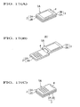
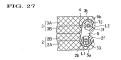
- the reception case 3 is to be returned to the folding position shown in FIG. 1(A) from the transmission position shown in FIG. 1(C) via the intermediate position shown in FIG. 1(B) after the reception case 3 is turned to the transmission position from the folding position via the intermediate position, the reception case 3 and the hinge main body 5 are turned in the same order as the reception case 3 and the hinge main body 5 of the portable cellular telephone set 1. That is, at the time the reception case 3 is turned to the intermediate position from the folding position, the hinge main body 5 is held in the stopped state shown in FIGS. 1(A) and 27. The position of the hinge main body 5 at that time is the first initial position.
- the reception case 3 is turned by a predetermined angle (100 degrees in this embodiment) to the second turning position shown in FIGS. 1(B) and 28 from the second initial position shown in FIGS. 1(A) and 27 about the second turning axis L2 with respect to the hinge main body 5.
- the reception case 3 is turned to the intermediate position from the folding position. Therefore, when the hinge main body 5 is located in the first initial position, the folding position and the second initial position of the reception case 3 are in the same position and the intermediate position and the second turning position are in the same position.
- the reception case 3 When it is attempted to turn the reception case 3 further toward the transmission position from the intermediate position, the reception case 3 is held in the stopped state with respect to the hinge main body 5, and the hinge main body 5 begins to turn toward the first turning position from the first initial position about the first turning axis L1. As a result, the reception case 3 is turned toward the transmission position from the intermediate position.
- the hinge main body 5 reaches the first turning position shown in FIGS. 1(C) and 29 by turning by a predetermined angle (60 degrees in this embodiment), the hinge main body 5 is stopped. At that time, the reception case 3 already reaches the transmission position by turning in unison with the hinge main body 5 about the first turning axis L1.
- reception case 3 In case the reception case 3 is to be turned to the intermediate position from the transmission position, the reception case 3 is held in the stopped state in the second turning position with respect to the hinge main body 5, and the hinge main body 5 is turned to the first initial position from the first turning position about the first turning axis L1. By this, the reception case 3 is turned to the intermediate position from the transmission position. At the time the reception case 3 is to be turned to the folding position from the intermediate position, the hinge main body 5 is held in the stopped state in the first initial position, and the reception case 3 is turned to the second initial position from the second turning position about the second turning axis L2 with respect to the hinge main body 5. By this, the reception case 3 is turned to the folding position from the intermediate position. In the folding position, the reception case 3 is not abutted with the transmission case 2 but the reception case 3 is slightly away from the transmission case 2.
- a pair of spherical bodies 66, 66 are symmetrically arranged with respect to the first turning axis L1 on the confronting surface of the first movable member 64 with the first turnable member 63. That is, the pair of spherical bodies 66, 66 are on the circumference about the first turning axis L1 in such a manner as to be 180 degrees away from each other in the peripheral direction.
- a pair of spherical bodies 76, 76 are arranged in the same relation between the pair of spherical bodies 66, 66 on the confronting surface of the second movable member 74 with the second turnable member 73.
- two pairs of the first engagement recesses 63A, 63B are formed on the confronting surface of the first turnable member 63 with the first movable member 64
- two pairs of recesses 73A, 73B are formed on the confronting surface of the second turnable member 73 with the second movable member 74.
- the two pairs of first engagement recesses 63A, 63B are arranged on the same circumference as the circumference on which the one pair of spherical bodies 66, 66 are arranged.
- the one pair of first engagement recesses 63A, 63B and the other pair of first engagement recesses 63A. 63B are symmetrically arranged about the first turning axis L1. That is, they are arranged 180 degrees away from each other in the peripheral direction.
- the first engagement recesses 63A, 63B are arranged away from each other in the peripheral direction by a predetermined angle (about 60 degrees in this embodiment).
- the two pairs of second engagement recesses 73A, 73B are arranged on the case circumference as the circumference on which the pair of spherical bodies 76, 76 are arranged.
- the one pair of second engagement recesses 73A, 73B and the other pair of second engagement recesses 73A, 73B are symmetrically arranged about the second turning axis L2. That is, they are arranged 180 degrees away from each other.
- the second engagement recesses 73A, 73B are arranged away from each other in the peripheral direction by a predetermined angle (about 100 degrees in this embodiment).
- the first engagement recess 63A includes inclination surfaces 63a, 63b having rising gradients rising toward the opposite end edges in the peripheral direction about the first turning axis L1 from the central part of the recess 63A.
- the inclination surfaces 63a, 63b are arranged such that when the hinge main body 5 is located in the first initial position, the spherical body 66 biased by the first coiled spring 65 is simultaneously press contacted with the inclination surfaces 63a, 63b. By this, the hinge main body 5 is held in the first initial position as long as no force acts on the hinge main body 5.
- the inclination surface 63a of the first engagement recess 63A converts the biasing force of the first coiled spring 65 into a turn biasing force.
- This turn biasing force prohibits the spherical body 66 from moving in the direction as indicated by an arrow X (in the peripheral direction about the first turning axis L1) of FIG. 32 through the first fixing member 61 and the first movable member 64 which would otherwise move in that direction when the hinge main body 5 is turned toward the first turning position from the first initial position.
- the turn biasing force of the first coiled spring 65 serves as a turn prohibiting force for prohibiting the hinge main body 5 from turning toward the first turning position from the first initial position. Therefore, the first conversion means 101 is constituted by the spherical body 66 and the inclination surface 63a, and the first turn prohibition means 111 is constituted by the first conversion means 101 and the first coiled spring 65,
- the inclination surface 63b of the first engagement recess 63A converts the biasing force of the first coiled spring 65 into a turn biasing force.
- This turn biasing force prohibits the spherical body 66 from moving in the direction as indicated by the arrow Y of FIG. 32, thereby stopping the hinge main body 5 in the first initial position, when the hinge main body 5 tends to move beyond the first initial position in case the hinge main body 5 is to be turned toward the first initial position from the first turning position about the first turning axis L1. Therefore, the second stop means 121 is constituted by the first coiled spring 65, the spherical body 66 and the inclination surface 63b.
- the first engagement recess 63B includes inclination surfaces 63c, 63d having a rising gradients rising toward the opposite end edges in the peripheral direction about the first turning axis L1 from the central part of the recess 63B.
- the inclination surfaces 63c, 63d are arranged such that when the hinge main body 5 is located in the first turning position, the spherical body 66 biased by the first coiled spring 65 is simultaneously press contacted with the inclination surfaces 63c, 63d. By this, the hinge main body 5 is held in the first turning position as long as no force acts on the hinge main body 5.
- the inclination surface 63c of the first engagement recess 63B converts the biasing force of the first coiled spring 65 into a turn biasing force.
- This turn biasing force prohibits the spherical body 66 from moving in the direction as indicated by an arrow Y which would otherwise move in that direction when the hinge main body 5 is turned toward the first initial position from the first turning position.
- the turn biasing force of the first coiled spring 65 serves as a turn prohibiting force for prohibiting the hinge main body 5 from turning toward the first initial position from the first turning position. Therefore, the second conversion means 102 is constituted by the spherical body 66 and the inclination surface 63c, and the second turn prohibition means 112 is constituted by the second conversion means 102 and the first coiled spring 65.
- the inclination surface 63d of the first engagement recess 63B converts the biasing force of the first coiled spring 65 into a turn biasing force.
- This turn biasing force prohibits the spherical body 66 from moving in the direction as indicated by the arrow X of FIG. 35, thereby stopping the hinge main body 5 in the first turning position, when the hinge main body 5 tends to move beyond the first turning position in case the hinge main body 5 is to be turned toward the first turning position from the first initial position about the first turning axis L1.
- the second stop means 122 is constituted by the first coiled spring 65, the spherical body 66 and the inclination surface 63d.
- the second engagement recess 73A includes inclination surfaces 73a, 73b having a rising gradients rising toward the opposite end edges in the peripheral direction about the second turning axis L2 from the central part of the recess 73A.
- the inclination surfaces 73a, 73b are arranged such that when the reception case 3 is located in the second initial position, the spherical body 76 biased by the second coiled spring 75 is simultaneously press contacted with the inclination surfaces 73a, 73b. By this, the reception section 3 is held in the second initial position as long as no force acts on the reception section 3.
- the inclination surface 73a of the second engagement recess 73A converts the biasing force of the second coiled spring 75 into a turn biasing force.
- This turn biasing force prohibits the second turnable member 73 from turning in the direction as indicated by the arrow X of FIG. 33, when the reception case 3 tends to turn toward the second turning position from the second initial position about the second turning axis L2, thereby the turn biasing force acts as a turn prohibiting force for prohibiting the reception case 3 from turning toward the second turning position from the second initial position.
- the third conversion means 103 is constituted by the spherical body 76 and the inclination surface 73a
- the third turn prohibition means 113 is constituted by the third conversion means 103 and the second coiled spring 75.
- the inclination surface 73b of the second engagement recess 73A converts the biasing force of the second coiled spring 75 into a turn biasing force.
- This turn biasing force prohibits the second turnable member 73 from moving in the direction as indicated by the arrow Y of FIG. 33 in accordance with the turning operation of the reception case 3, thereby stopping the reception case 3 in the second initial position, when the reception case 3 tends to move beyond the second initial position in case the reception case 3 is to be turned toward the second initial position from the second turning position. Therefore, the third stop means 123 is constituted by the second coiled spring 75, the inclination surface 73b and the spherical body 76.
- the second engagement recess 73B includes inclination surfaces 73c, 73d having rising gradients rising toward the opposite end edges in the peripheral direction about the second turning axis L2 from the central part of the recess 73B.
- the inclination surfaces 73c, 73d are arranged such that when the reception case 3 is located in the second turning position, the spherical body 76 biased by the second coiled spring 75 is simultaneously press contacted with the inclination surfaces 73c, 73d. By this, the reception section 3 is held in the second turning position as long as no force acts on the reception section 3.
- the inclination surface 73c of the second engagement recess 73B converts the biasing force of the second coiled spring 75 into a turn biasing force.
- This turn biasing force prohibits the second turnable member 73 from turning in the direction as indicated by the arrow X of FIG. 33, when the reception case 3 tends to turn toward the second initial position from the second turning position about the second turning axis L2, thereby the turn biasing force acts as a turn prohibiting force for prohibiting the reception case 3 from turning toward the second initial position from the second turning position.
- the fourth conversion means 104 is constituted by the spherical body 76 and the inclination surface 73c
- the fourth turn prohibition means 114 is constituted by the fourth conversion means 104 and the second coiled spring 75.
- the inclination surface 73d of the second engagement recess 73B converts the biasing force of the second coiled spring 75 into a turn biasing force.
- This turn biasing force prohibits the second turnable member 73 from turning in the direction as indicated by the arrow X of FIG. 34 when the reception case 3 tends to turn beyond the second turning position in case the reception case 3 is to be turned toward the second turning position from the second initial position, thereby the turn biasing force prohibits the reception case 3 from turning beyond the second turning position and stops the reception case 3 in the second turning position. Therefore, the fourth stop means 124 is constituted by the second coiled spring 75, the inclination surface 73d and the spherical body 76.
- the turn prohibiting force and the stopping force of the respective means 111 through 114 and 121 through 124 are compared. Presume that the reception case 3 is located in the folding position. That is, presume that the hinge main body 5 is located in the first initial position and the reception case 3 is located in the second initial position.
- the first turn prohibition means 111 prohibits the hinge main body 5 from turning toward the first turning position from the first initial position
- the third turn prohibition means 113 prohibits the reception case 3 from turning toward the second turning position from the second initial position.
- the hinge main body 5 is held in the first initial position and the reception case 3 is turned toward the second turning position from the second initial position against the turn biasing force of the third turn biasing means 113.
- the first turn prohibition means 111 prevents the hinge main body 5 from turning toward the first turning position from the first initial position and the fourth stop means prohibits the reception case 3 from turning beyond the second turning position.
- the inclination angle of the inclination surface 73d of the second engagement recess 73B which constitutes a part of the fourth stop means 10D is represented by ⁇ 2 (see FIG. 16), the following expression can be established.
- the turn prohibiting force of the first turn prohibition means 111 is compared with the turn prohibiting force of the fourth stop means 124, the latter is larger than the former.
- the reception case 3 located in the intermediate position is turned toward the transmission position, the reception case 3 is prohibited from turning beyond the second turning position with respect to the hinge main body 5 and held in the stopped state in the second turning position.
- the hinge main body 5 is turned toward the first turning position from the first initial position against the turn prohibiting force of the first turn prohibition means 111.
- the reception case 3 In case the reception case 3 is located in the transmission position, the reception case 3 is located in the first turning position with respect to the hinge main body 5 and the hinge main body 5 is located in the second turning position.
- the second turn prohibition means 112 prohibits the spherical body 66 from moving in the direction as indicated by the arrow Y of FIG. 18 and thus, prohibits the hinge main body 5 from turning toward the first initial position from the first turning position.
- the fourth turn prohibition means 114 prohibits the second turnable member 73 from turning in the direction as indicated by the arrow X of FIG. 34, and thus, prohibits the reception case 3 from turning toward the second initial position from the second turning position.
- the hinge main body 5 When the reception case 3 is located in the intermediate position, the hinge main body 5 is located in the first initial position and the reception case 3 is located in the second turning position with respect to the hinge main body 5.
- the first stop means 121 prohibits the spherical body 66 from moving in the direction as indicated by the arrow Y of FIG. 32 and prohibits the hinge main body 5 from turning beyond the first initial position.
- the fourth turn prohibition means 114 prohibits the second turnable member 73 from turning in the direction as indicated by the arrow Y of FIG. 34 and prohibits the reception case 3 from turning toward the second initial position from the second turning position.
- the angle ⁇ 3 is set to be same as the angle ⁇ 2.
- the inclination angle of the inclination surface 63d of the first engagement recess 63B which constitutes a part of the second stop means 122 is represented by ⁇ 4 (see FIG. 32) and the inclination angle of the inclination surface 73b of the second engagement recess 73A which constitutes a part of the third stop means 123, by ⁇ 4 (see FIG. 33), respectively, the following expression can be established.
- the reception case 3 In the portable cellular telephone set 1 constructed in the manner as mentioned above, presume that the reception case 3 is located in the folding position. In that state, as shown in FIG. 32, the spherical body 66 is in contact with the inclination surfaces 63a, 63b of the first engagement recess 63A, and as shown in FIG. 33, the spherical body 76 is in contact with the inclination surfaces 73a, 73b of the second engagement recess 73A.
- the hinge main body 5 When the reception case 3 is turned toward the transmission position, the hinge main body 5 is held in the stopped state in the first initial position and the reception case 3 is turned toward the second turning position from the second initial position against the turn biasing force of the third turn prohibition means 113.
- the reception case 3 When the reception case 3 is moved by a predetermined angle (for example, 10 degrees) from the second initial position, the spherical body 76 is escaped from the second engagement recess 73A. Then, the spherical body 76 is contacted with the confronting surface of the second turnable member 73 with the second movable member 74.
- This confronting surface is a plane orthogonal to the second turning axis L2. Therefore, a frictional resistance in correspondence with the biasing force of the coiled spring 75 is generated between the confronting surface and the spherical body 76.
- the reception case 3 can be stopped in an optional position within a range after the spherical body 76 is escaped from the second engagement recess 73A until the spherical body 76 is entered into the second engagement recess 73B.
- the reception case 3 When the reception case 3 reaches a position which is located before the intermediate position by a predetermined angle (for example, 10 degrees), the spherical body 76 is contacted with the inclination surface 73c of the second engagement recess 73B. Then, the reception case 3 is automatically turned to the intermediate position (second turning position) by the biasing force of the fourth turn prohibition means 114. When the reception case 3 reaches the intermediate position, the spherical body 76 is abutted with the inclination surface 73d and stopped and the reception case 3 is stopped in the intermediate position. At that time, as shown in FIG.
- a predetermined angle for example, 10 degrees
- the spherical body 66 is already contacted with the inclination surfaces 63a, 63b of the first engagement recess 63A, and as shown in FIG. 34, the spherical body 76 is already contacted with the inclination surfaces 73c, 73d of the second engagement recess 73B.
- the reception case 3 is to be turned toward the transmission position from the intermediate position, the reception case 3 is held in the stopped state in the second turning position and the hinge main body 5 is turned toward the first turning position from the first initial position against the biasing force of the first turn prohibition means 111.
- the hinge main body 5 is turned by a predetermined angle from the first initial position, the spherical body 66 is escaped from the first engagement recess 63A and contacted with the confronting surface of the first turnable member 63 with the first movable member 64.
- This confronting surface is a plane orthogonal to the first turning axis L1. Therefore, a frictional resistance in correspondence with the biasing force of the coiled spring 65 is generated between the confronting surface and the spherical body 66.
- the reception case 3 can be stopped in an optional position within a range after the spherical body 66 is escaped from the first engagement recess 63A until the spherical body 66 is entered into the first engagement recess 63B.
- the reception case 3 When the reception case 3 reaches a position which is located before the transmission position by a predetermined angle (for example, 10 degrees), in other words, when the hinge main body 5 reaches a position which is located before the first turning position by a predetermined angle, the spherical body 66 is contacted with the inclination surface 63c of the first engagement recess 63B. Then, the hinge main body 5 is automatically turned to the first turning position by the biasing force of the second turn prohibition means 112. In accompany therewith, the reception case 3 is turned to the transmission position. When the reception case 3 reaches the transmission position, the spherical body 66 is abutted with the inclination surface 63d and stopped, and the reception case 3 is stopped in the transmission position.
- a predetermined angle for example, 10 degrees
- the spherical body 66 is already contacted with the inclination surfaces 63c, 63d of the first engagement recess 63B and the spherical body 76 is already contacted with the inclination surfaces 73c, 73d of the second engagement recess 73b.
- the reception case 3 stopped in the transmission position can be further turned beyond the transmission position against the biasing force of the second stop means 122 or fourth stop means 124.
- the reception case 3 is turned by a small angle beyond the transmission position, one end part of the reception case 3 is abutted with one end part of the transmission case 2 and stopped immediately, thereby the reception case 3 is unable to turn any further in that direction.
- the position where the reception case 3 is abutted with the transmission case 2 may be arranged as a transmission position.
- the spherical body 66 is located in a position which is located immediately before the body 66 is abutted with the inclination surface 63d, and that the reception case 3 is held in the abutted state (the state where the reception case 3 is located in the transmission position) with the transmission case 2 by the biasing force of the second turn prohibition means 112.
- the reception case 3 is to be turned toward the intermediate position from the transmission position, the reception case 3 is held in the stopped state in the second turning position and the hinge main body 5 is turned toward the first initial position from the first turning position against the biasing force of the second turn prohibition means 112.
- the hinge main body 5 is turned to a position which is located before the first initial position by a predetermined angle (for example, 10 degrees)
- the spherical body 66 is contacted with the inclination surface 73a of the first engagement recess 63A.
- the hinge main body 5 is automatically turned to the first initial position by the turn biasing force of the first turn prohibition means 111.
- the hinge main body 5 reached the first initial position is stopped in the intermediate position since the spherical body 66 is abutted with the inclination surface 63b of the first engagement recess 63A and stopped.
- the reception case 3 which is turned in unison with the hinge main body 5, is turned to the intermediate position from the transmission position and stopped in the intermediate position.
- the reception case 3 can be stopped in an optional position by the frictional resistance acting between the spherical body 66 and the first turnable member 63 as in the above-mentioned case.
- the hinge main body 5 is held in the stopped state in the first initial position and the reception case 3 is turned toward the second initial position from the second turning position against the turn biasing force of the fourth turn prohibition means 114,
- the spherical body 76 reaches a position which is located before the second initial position by a predetermined angle (for example, 10 degrees)
- the spherical body 76 is contacted with the inclination surface 73a of the second engagement recess 73A.
- the reception case 3 is automatically turned to the second initial position by the turn biasing force of the third turn prohibition means 113.
- the reception case 3 When the reception case 3 is turned to the second initial position, the spherical body 76 is abutted with the inclination surface 73b of the first engagement recess 73A. By this, the reception case 3 is stopped. At that time, the reception case 3 already reaches the folding position. By this, the portable cellular telephone set 1 is returned to the original state.
- the reception case 3 located in the folding position can be further turned beyond the turn biasing force of the first stop means 121 or third stop means 123.
- the front surface 3a of the reception case 3 is immediately abutted with the front surface 2a of the transmission case 2 and stopped, thereby the reception case 3 is unable to turn any further in that direction.
- the position where the reception case 3 is abutted with the transmission case 2 may be arranged as the folding position.
- the transmission case 2 and the reception case 3 are turnably connected to each other through the two-axis hinge apparatus 4 in this embodiment, the turning order between the reception case 3 and the hinge main body 5 can be made normally constant. Accordingly, the user of the portable cellular telephone set 1 can be prevented from getting a sense of uncomfortability.
- a third mode of the present invention when the reception case 3 is turned up to the transmission position from the folding position via the intermediate position, first, the hinge main body 5 is turned to the first turning position from the first initial position so that the reception case 3 is turned to the intermediate position and thereafter, the reception case 3 is turned to the second turning position from the second initial position so that the reception case 3 is turned to the transmission position.
- the turning order between the reception case 3 and the hinge main body 5 during the time the reception case 3 is turned to the folding position from the transmission position is same as in the above-mentioned embodiments.
- the following expression is employed between the inclination angle ⁇ 1 of the inclination surface 63a of the first engagement recess 63A which constitutes a part of the first turn prohibition means 111 and the inclination angle ⁇ 1 of the inclination surface 73a of the second engagement recess 73A which constitutes a part of the third turn prohibition means 113.
- ⁇ 1 ⁇ ⁇ 1 As a result, the turn prohibiting force (turn biasing force) of the third turn prohibition means 113 is larger than the turn prohibiting force of the first turn prohibition means 111. Accordingly, at the time the reception case 3 is turned to the intermediate position from the folding position, the reception case 3 is held in the stopped state with respect to the hinge main body 5 and the hinge main body 5 is turned to the first turning position from the first initial position.
- the hinge main body 5 is held in the stopped state in the first turning position and the reception case 3 is turned to the second turning position from the second initial position.
- the inclination angle ⁇ 4 of the inclination surface 63d of the first engagement recess 63B is set to be larger than the inclination angle ⁇ 1 of the inclination surface 73a of the second engagement recess 73A.
- the turn stopping force of the second stop means 122 is larger than the turn prohibiting force of the third turn prohibition means 113. Therefore, at the time the reception case 3 is turned to the transmission position from the intermediate position, the hinge main body 5 is held in the stopped state and the reception case 3 is turned.
- the hinge main body 5 is turned to the first turning position from the first initial position after the reception case 3 is turned to the second turning position from the second initial position.
- the hinge main body 5 is turned to the first initial position from the first turning position after the reception case 3 is turned to the first turning position from the second turning position.
- the expression ⁇ 2 > ⁇ 3 is employed.
- the employment of such angular relationship enables to make the turn prohibiting force (turn biasing force) of the second turn prohibition means 112 larger than the turn prohibiting force of the fourth turn prohibition means 114. Accordingly, at the time the reception case 3 is turned toward the intermediate position from the transmission position, the hinge main body 5 is held in the stopped state in the first turning position and the reception case 3 is turned to the second initial position from the second turning position.
- the expression ⁇ 2 ⁇ ⁇ 4 is employed.
- the employment of such angular relationship enables to make the turn stopping force (turn biasing force) of the third turn stop means 123 larger than the turn prohibiting force (turn biasing force) of the second turn prohibition means 112. Accordingly, at the time the reception case 3 is turned to the folding position from the intermediate position, the reception case 3 is held in the stopped state in the second initial position and the hinge main body 5 is turned to the first initial position from the intermediate position.
- the turning order between the reception case 3 and the hinge main body 5 can be made entirely reversed to the turning order in the second mode.
- the hinge main body 5 is turned to the first turning position from the first initial position thereby allowing the reception case 3 to turn to the intermediate position from the folding position, and thereafter, the reception case 3 is turned to the second turning position from the second initial position thereby allowing the reception case 3 to turn to the transmission position from the intermediate position.
- the hinge main body 5 is turned to the first initial position from the first turning position after the reception case 3 is turned to the second initial position from the second turning position thereby allowing the reception case 3 to turn to the folding position from the transmission position via the intermediate position.
- a plane parallel to the first and second turning axes L1, L2 may be employed.
- first and second fixing members 61, 71 may be integrally formed with the hinge main body 5.
- first and second movable members 64, 74 are movably but non-turnably disposed at the hinge main body 5.
- the present invention can be utilized as a connecting apparatus or a two-hinge apparatus for turnably connecting a transmission case and a reception case of a portable cellular telephone set or a main body case and a display case of a notebook type personal computer.
Landscapes
- Engineering & Computer Science (AREA)
- Signal Processing (AREA)
- Pivots And Pivotal Connections (AREA)
- Telephone Set Structure (AREA)
Applications Claiming Priority (3)
| Application Number | Priority Date | Filing Date | Title |
|---|---|---|---|
| JP2003100482A JP4090930B2 (ja) | 2003-04-03 | 2003-04-03 | 機器ケースの開閉装置 |
| JP2003315570A JP4265948B2 (ja) | 2003-09-08 | 2003-09-08 | 2軸ヒンジ装置及び携帯機器 |
| PCT/JP2004/004853 WO2004090355A1 (fr) | 2003-04-03 | 2004-04-02 | Dispositif d'ouverture/fermeture de boite de dispositif et dispositif articule a 2 axes |
Publications (2)
| Publication Number | Publication Date |
|---|---|
| EP1614913A1 true EP1614913A1 (fr) | 2006-01-11 |
| EP1614913A4 EP1614913A4 (fr) | 2008-06-11 |
Family
ID=33161501
Family Applications (1)
| Application Number | Title | Priority Date | Filing Date |
|---|---|---|---|
| EP04725541A Withdrawn EP1614913A4 (fr) | 2003-04-03 | 2004-04-02 | Dispositif d'ouverture/fermeture de boite de dispositif et dispositif articule a 2 axes |
Country Status (3)
| Country | Link |
|---|---|
| US (1) | US7484271B2 (fr) |
| EP (1) | EP1614913A4 (fr) |
| WO (1) | WO2004090355A1 (fr) |
Cited By (10)
| Publication number | Priority date | Publication date | Assignee | Title |
|---|---|---|---|---|
| EP2081367A1 (fr) | 2008-01-18 | 2009-07-22 | Research In Motion Limited | Dispositif de communication électronique portable de type coque doté d'un interconnecteur couplé en pivotement |
| US7765644B2 (en) | 2005-01-25 | 2010-08-03 | Sanyo Electric Co., Ltd. | Hinge device |
| US7907415B2 (en) | 2005-07-28 | 2011-03-15 | Sanyo Electric Co., Ltd. | Hinge mechanism of foldable device, and foldable device provided with hinge mechanism |
| US7930803B2 (en) | 2005-08-02 | 2011-04-26 | Sanyo Electric Co., Ltd. | Foldable device |
| EP1983201A4 (fr) * | 2006-01-24 | 2011-09-21 | Strawberry Corp Kk | Articulation et appareil electronique utilisant l'articulation |
| US8489157B2 (en) | 2008-01-18 | 2013-07-16 | Research In Motion Limited | Handheld electronic device with extended dual-hinged interconnector |
| US8611971B2 (en) | 2008-01-18 | 2013-12-17 | Blackberry Limited | Hinging interconnector for a clamshell handheld electronic communication device |
| CN103573799A (zh) * | 2012-07-31 | 2014-02-12 | 宏碁股份有限公司 | 折叠式电子设备 |
| US9307660B2 (en) | 2012-07-31 | 2016-04-05 | Acer Incorporated | Electronic equipment |
| WO2021162212A1 (fr) | 2020-02-10 | 2021-08-19 | Samsung Electronics Co., Ltd. | Structure de charnière et appareil électronique pliable la comprenant |
Families Citing this family (40)
| Publication number | Priority date | Publication date | Assignee | Title |
|---|---|---|---|---|
| JP2005207465A (ja) * | 2004-01-21 | 2005-08-04 | Sugatsune Ind Co Ltd | ニ軸ヒンジ装置 |
| KR100630098B1 (ko) * | 2004-02-20 | 2006-09-27 | 삼성전자주식회사 | 휴대용 디지털 통신 장치 |
| WO2007007705A1 (fr) * | 2005-07-12 | 2007-01-18 | Sugatsune Kogyo Co., Ltd. | Dispositif de charniere |
| US20070254729A1 (en) * | 2006-05-01 | 2007-11-01 | Freund Joseph M | Handheld portable electronic device with integrated stand |
| DE102008013560B4 (de) * | 2008-03-28 | 2010-01-28 | E-LEAD ELECTRONIC CO., LTD., Shengang Shiang | Doppelachsenkonstruktion mit extremem Biegungswinkel |
| TWI346275B (en) * | 2008-06-16 | 2011-08-01 | Asustek Comp Inc | Biaxial module and portable electronic apparatus having biaxial module |
| TWI366307B (en) * | 2008-09-25 | 2012-06-11 | Asustek Comp Inc | Electronic device and card fixing module thereof |
| US7900323B2 (en) * | 2008-10-02 | 2011-03-08 | Shin Zu Shing Co., Ltd. | Hinge and a lamp with the hinge |
| US8804317B2 (en) | 2009-07-01 | 2014-08-12 | Sharp Kabushiki Kaisha | Display device |
| JP2011061692A (ja) * | 2009-09-14 | 2011-03-24 | Sony Corp | 電子機器 |
| CN102076200B (zh) * | 2009-11-24 | 2014-11-05 | 鸿富锦精密工业(深圳)有限公司 | 电子设备 |
| US8467179B2 (en) | 2010-01-28 | 2013-06-18 | Cruxcase, Llc | Tablet computer case and associated methods |
| US8467183B2 (en) | 2010-01-28 | 2013-06-18 | Cruxcase, Llc | Tablet computer case and associated methods |
| US20110199727A1 (en) * | 2010-01-28 | 2011-08-18 | Brian Probst | Tablet computer case and associated methods |
| CN102221040A (zh) * | 2010-04-15 | 2011-10-19 | 鸿富锦精密工业(深圳)有限公司 | 铰链结构 |
| US8573394B2 (en) * | 2010-05-06 | 2013-11-05 | Clamcase, Llc | Electronic device case and method of use |
| JP5864148B2 (ja) * | 2010-07-12 | 2016-02-17 | 三菱製鋼株式会社 | 電子機器用ヒンジ装置 |
| US20120137471A1 (en) * | 2010-12-03 | 2012-06-07 | Nokia Corporation | Hinge Apparatus and Method |
| US9535465B2 (en) * | 2011-02-10 | 2017-01-03 | Microsoft Technology Licensing, Llc | Hinge electrical interconnection guide |
| US8780570B2 (en) | 2011-02-14 | 2014-07-15 | Microsoft Corporation | Double hinge torsion bar |
| JP2012173878A (ja) * | 2011-02-18 | 2012-09-10 | Toshiba Corp | 電子機器 |
| US8773849B2 (en) | 2011-04-11 | 2014-07-08 | Microsoft Corporation | Extendable connecting link |
| US8578561B2 (en) | 2012-01-19 | 2013-11-12 | Shin Zu Shing Co., Ltd. | Dual-axis hinge and portable device with the same |
| CN103307094B (zh) * | 2012-03-09 | 2015-06-24 | 兆利科技工业股份有限公司 | 卡锁式双轴枢纽器 |
| US20140226274A1 (en) * | 2013-02-12 | 2014-08-14 | Lenovo (Singapore) Pte. Ltd. | Devices and methods for opening a computing device with a user cue |
| US9201465B2 (en) * | 2013-03-15 | 2015-12-01 | Dell Products L.P. | Information handling system housing lid with synchronized motion |
| US9500013B2 (en) | 2013-07-25 | 2016-11-22 | Hewlett-Packard Development Company, L.P. | Hinge assembly for a computing device |
| US20150309539A1 (en) * | 2014-04-25 | 2015-10-29 | Dell Products L.P. | Information Handling System Housing Synchronization with Differential Torque Hinge |
| USD742871S1 (en) | 2014-06-05 | 2015-11-10 | Incipio Technologies, Inc. | Computer case |
| USD755781S1 (en) | 2014-06-05 | 2016-05-10 | Incipio, Llc | Computer case |
| US10227808B2 (en) | 2015-11-20 | 2019-03-12 | Microsoft Technology Licensing, Llc | Hinged device |
| US9489054B1 (en) | 2016-01-05 | 2016-11-08 | Zagg Intellectual Property Holding Co., Inc. | Keyboard folio with attachment strip |
| US9557776B1 (en) | 2016-05-10 | 2017-01-31 | Zagg Intellectual Property Holding Co., Inc. | Friction resistance hinge with auto-lock |
| US10474203B2 (en) | 2016-09-01 | 2019-11-12 | Microsoft Technology Licensing, Llc | Hinged device |
| US10364598B2 (en) | 2016-09-02 | 2019-07-30 | Microsoft Technology Licensing, Llc | Hinged device |
| US10241548B2 (en) | 2016-12-09 | 2019-03-26 | Microsoft Technology Licensing, Llc | Computing device employing a self-spacing hinge assembly |
| US10641318B2 (en) | 2016-12-09 | 2020-05-05 | Microsoft Technology Licensing, Llc | Hinged device |
| US10253804B2 (en) * | 2017-01-24 | 2019-04-09 | Microsoft Technology Licensing, Llc | Hinged device |
| US10296044B2 (en) | 2017-06-08 | 2019-05-21 | Microsoft Technology Licensing, Llc | Hinged device |
| US10344510B2 (en) | 2017-06-16 | 2019-07-09 | Microsoft Technology Licensing, Llc | Hinged device |
Family Cites Families (20)
| Publication number | Priority date | Publication date | Assignee | Title |
|---|---|---|---|---|
| JPH057629Y2 (fr) * | 1986-08-29 | 1993-02-25 | ||
| JPH02134316U (fr) * | 1989-04-14 | 1990-11-07 | ||
| JPH0715186Y2 (ja) * | 1989-04-11 | 1995-04-10 | カシオ計算機株式会社 | 機器ケースの開閉構造 |
| DE4016875C2 (de) | 1990-05-25 | 1994-02-17 | Rudi Broghammer | Zweiachsige Scharnierverbindung |
| JPH05265590A (ja) * | 1992-03-19 | 1993-10-15 | Hitachi Ltd | 電子機器 |
| US5666694A (en) * | 1995-09-28 | 1997-09-16 | Hewlett-Packard Company | Hinge arrangement |
| JP3816202B2 (ja) * | 1997-07-31 | 2006-08-30 | スガツネ工業株式会社 | 折り畳み式機器のカバーを広角度開閉保持可能としたヒンジ装置 |
| JP3031903B1 (ja) * | 1998-12-25 | 2000-04-10 | 三菱製鋼株式会社 | ヒンジ機構 |
| US6253419B1 (en) * | 2000-01-13 | 2001-07-03 | Lu Sheng-Nan | Pivot device with multiple pivotal bars for a notebook computer |
| JP3830745B2 (ja) * | 2000-09-29 | 2006-10-11 | スガツネ工業株式会社 | ヒンジ装置 |
| JP2002118633A (ja) * | 2000-10-06 | 2002-04-19 | Nec Corp | 折り畳み式携帯電話機 |
| US7047599B2 (en) * | 2000-12-11 | 2006-05-23 | Sugatsune Kogyo Co., Ltd. | Hinge assembly |
| WO2002068833A1 (fr) * | 2001-02-26 | 2002-09-06 | Sugatsune Kogyo Co., Ltd. | Dispositif d'articulation |
| JP4141651B2 (ja) * | 2001-02-28 | 2008-08-27 | スガツネ工業株式会社 | ヒンジ装置 |
| JP3986794B2 (ja) * | 2001-10-19 | 2007-10-03 | 株式会社オーハシテクニカ | ヒンジ装置及びそれを用いた携帯電話機 |
| US6900981B2 (en) * | 2003-04-23 | 2005-05-31 | Nokia Corporation | Mobile Terminal with synchronizing hinge |
| US7155266B2 (en) * | 2004-04-21 | 2006-12-26 | Nokia Corporation | Hinge for fold phone |
| US7426406B2 (en) * | 2003-04-23 | 2008-09-16 | Nokia Corporation | Mobile communications device with synchronising hinge |
| US7140074B2 (en) * | 2004-01-20 | 2006-11-28 | Phoenix Korea Co., Ltd. | Hand-held electronic device including hinge device |
| JP4111957B2 (ja) * | 2004-04-09 | 2008-07-02 | フェニックス コリア 株式会社 | 回転して広げられたり折り畳まれたりできる二つのユニットを備える携帯装置及びその携帯装置に使用されるヒンジ装置 |
-
2004
- 2004-04-02 EP EP04725541A patent/EP1614913A4/fr not_active Withdrawn
- 2004-04-02 WO PCT/JP2004/004853 patent/WO2004090355A1/fr not_active Ceased
- 2004-04-02 US US10/551,623 patent/US7484271B2/en not_active Expired - Fee Related
Cited By (13)
| Publication number | Priority date | Publication date | Assignee | Title |
|---|---|---|---|---|
| US7765644B2 (en) | 2005-01-25 | 2010-08-03 | Sanyo Electric Co., Ltd. | Hinge device |
| US7907415B2 (en) | 2005-07-28 | 2011-03-15 | Sanyo Electric Co., Ltd. | Hinge mechanism of foldable device, and foldable device provided with hinge mechanism |
| US7930803B2 (en) | 2005-08-02 | 2011-04-26 | Sanyo Electric Co., Ltd. | Foldable device |
| EP1983201A4 (fr) * | 2006-01-24 | 2011-09-21 | Strawberry Corp Kk | Articulation et appareil electronique utilisant l'articulation |
| US8611971B2 (en) | 2008-01-18 | 2013-12-17 | Blackberry Limited | Hinging interconnector for a clamshell handheld electronic communication device |
| US8489157B2 (en) | 2008-01-18 | 2013-07-16 | Research In Motion Limited | Handheld electronic device with extended dual-hinged interconnector |
| EP2081367A1 (fr) | 2008-01-18 | 2009-07-22 | Research In Motion Limited | Dispositif de communication électronique portable de type coque doté d'un interconnecteur couplé en pivotement |
| CN103573799A (zh) * | 2012-07-31 | 2014-02-12 | 宏碁股份有限公司 | 折叠式电子设备 |
| US9307660B2 (en) | 2012-07-31 | 2016-04-05 | Acer Incorporated | Electronic equipment |
| WO2021162212A1 (fr) | 2020-02-10 | 2021-08-19 | Samsung Electronics Co., Ltd. | Structure de charnière et appareil électronique pliable la comprenant |
| CN115053197A (zh) * | 2020-02-10 | 2022-09-13 | 三星电子株式会社 | 铰链结构和包括该铰链结构的可折叠电子设备 |
| EP4028857A4 (fr) * | 2020-02-10 | 2022-11-30 | Samsung Electronics Co., Ltd. | Structure de charnière et appareil électronique pliable la comprenant |
| CN115053197B (zh) * | 2020-02-10 | 2024-05-14 | 三星电子株式会社 | 铰链结构和包括该铰链结构的可折叠电子设备 |
Also Published As
| Publication number | Publication date |
|---|---|
| HK1089806A1 (zh) | 2006-12-08 |
| US20060179612A1 (en) | 2006-08-17 |
| US7484271B2 (en) | 2009-02-03 |
| EP1614913A4 (fr) | 2008-06-11 |
| WO2004090355A1 (fr) | 2004-10-21 |
Similar Documents
| Publication | Publication Date | Title |
|---|---|---|
| EP1614913A1 (fr) | Dispositif d'ouverture/fermeture de boite de dispositif et dispositif articule a 2 axes | |
| US6785936B2 (en) | Hinge device | |
| CN100412392C (zh) | 用于设备壳体的开关装置及其双轴铰接装置 | |
| US6115886A (en) | Hinge apparatus | |
| EP1707829A1 (fr) | Dispositif d'articulation comportant deux axes | |
| EP2090792B1 (fr) | Mécanisme d'articulation | |
| US7895710B2 (en) | Hinge device | |
| TWI221888B (en) | Hinge assembly | |
| JP4801806B2 (ja) | チェッカ付きドアヒンジ | |
| EP1703150A1 (fr) | Dispositif charniere | |
| US6543088B2 (en) | Hinge assembly | |
| US6587676B1 (en) | Hinge assembly | |
| EP1767796A1 (fr) | Dispositif d"articulation à deux axes | |
| GB2432190A (en) | Hinge device | |
| JP4853350B2 (ja) | ヒンジ装置および携帯電話 | |
| EP1312739B1 (fr) | Telephone cellulaire pliable | |
| CN1981108A (zh) | 铰链装置 | |
| JP4954027B2 (ja) | ヒンジ装置並びにヒンジ装置を用いた機器 | |
| HK1089806B (en) | Opening/closing apparatus for equipment case and two-axis hinge apparatus thereof | |
| JP2000017932A (ja) | ヒンジ装置 | |
| TWI813212B (zh) | 開闔裝置及應用此開闔裝置的終端機器 | |
| JP5093887B2 (ja) | ヒンジ装置 | |
| US20060196009A1 (en) | Hinge device |
Legal Events
| Date | Code | Title | Description |
|---|---|---|---|
| PUAI | Public reference made under article 153(3) epc to a published international application that has entered the european phase |
Free format text: ORIGINAL CODE: 0009012 |
|
| 17P | Request for examination filed |
Effective date: 20051024 |
|
| AK | Designated contracting states |
Kind code of ref document: A1 Designated state(s): AT BE BG CH CY CZ DE DK EE ES FI FR GB GR HU IE IT LI LU MC NL PL PT RO SE SI SK TR |
|
| AX | Request for extension of the european patent |
Extension state: AL HR LT LV MK |
|
| DAX | Request for extension of the european patent (deleted) | ||
| A4 | Supplementary search report drawn up and despatched |
Effective date: 20080513 |
|
| RIC1 | Information provided on ipc code assigned before grant |
Ipc: E05D 11/10 20060101ALI20080506BHEP Ipc: E05D 3/06 20060101ALI20080506BHEP Ipc: H05K 5/03 20060101ALI20080506BHEP Ipc: H05K 5/02 20060101ALI20080506BHEP Ipc: F16C 11/04 20060101ALI20080506BHEP Ipc: F16C 11/10 20060101ALI20080506BHEP Ipc: H04M 1/02 20060101AFI20080506BHEP |
|
| 17Q | First examination report despatched |
Effective date: 20120308 |
|
| STAA | Information on the status of an ep patent application or granted ep patent |
Free format text: STATUS: THE APPLICATION IS DEEMED TO BE WITHDRAWN |
|
| 18D | Application deemed to be withdrawn |
Effective date: 20141031 |