EP1614924B1 - Schwimmsattel-Scheibenbremse mit Mittel zum Vermeiden der Formveränderung des Bremsträgers während eines Bremsvorgangs - Google Patents
Schwimmsattel-Scheibenbremse mit Mittel zum Vermeiden der Formveränderung des Bremsträgers während eines Bremsvorgangs Download PDFInfo
- Publication number
- EP1614924B1 EP1614924B1 EP05014441A EP05014441A EP1614924B1 EP 1614924 B1 EP1614924 B1 EP 1614924B1 EP 05014441 A EP05014441 A EP 05014441A EP 05014441 A EP05014441 A EP 05014441A EP 1614924 B1 EP1614924 B1 EP 1614924B1
- Authority
- EP
- European Patent Office
- Prior art keywords
- disc
- rail
- disc brake
- brake
- slideway
- Prior art date
- Legal status (The legal status is an assumption and is not a legal conclusion. Google has not performed a legal analysis and makes no representation as to the accuracy of the status listed.)
- Ceased
Links
- 238000011144 upstream manufacturing Methods 0.000 claims description 13
- 230000005540 biological transmission Effects 0.000 description 4
- 230000000694 effects Effects 0.000 description 2
- 230000002093 peripheral effect Effects 0.000 description 2
- 230000004323 axial length Effects 0.000 description 1
- 230000007423 decrease Effects 0.000 description 1
Images


Classifications
-
- F—MECHANICAL ENGINEERING; LIGHTING; HEATING; WEAPONS; BLASTING
- F16—ENGINEERING ELEMENTS AND UNITS; GENERAL MEASURES FOR PRODUCING AND MAINTAINING EFFECTIVE FUNCTIONING OF MACHINES OR INSTALLATIONS; THERMAL INSULATION IN GENERAL
- F16D—COUPLINGS FOR TRANSMITTING ROTATION; CLUTCHES; BRAKES
- F16D55/00—Brakes with substantially-radial braking surfaces pressed together in axial direction, e.g. disc brakes
- F16D55/02—Brakes with substantially-radial braking surfaces pressed together in axial direction, e.g. disc brakes with axially-movable discs or pads pressed against axially-located rotating members
- F16D55/22—Brakes with substantially-radial braking surfaces pressed together in axial direction, e.g. disc brakes with axially-movable discs or pads pressed against axially-located rotating members by clamping an axially-located rotating disc between movable braking members, e.g. movable brake discs or brake pads
- F16D55/224—Brakes with substantially-radial braking surfaces pressed together in axial direction, e.g. disc brakes with axially-movable discs or pads pressed against axially-located rotating members by clamping an axially-located rotating disc between movable braking members, e.g. movable brake discs or brake pads with a common actuating member for the braking members
- F16D55/225—Brakes with substantially-radial braking surfaces pressed together in axial direction, e.g. disc brakes with axially-movable discs or pads pressed against axially-located rotating members by clamping an axially-located rotating disc between movable braking members, e.g. movable brake discs or brake pads with a common actuating member for the braking members the braking members being brake pads
- F16D55/226—Brakes with substantially-radial braking surfaces pressed together in axial direction, e.g. disc brakes with axially-movable discs or pads pressed against axially-located rotating members by clamping an axially-located rotating disc between movable braking members, e.g. movable brake discs or brake pads with a common actuating member for the braking members the braking members being brake pads in which the common actuating member is moved axially, e.g. floating caliper disc brakes
- F16D55/2265—Brakes with substantially-radial braking surfaces pressed together in axial direction, e.g. disc brakes with axially-movable discs or pads pressed against axially-located rotating members by clamping an axially-located rotating disc between movable braking members, e.g. movable brake discs or brake pads with a common actuating member for the braking members the braking members being brake pads in which the common actuating member is moved axially, e.g. floating caliper disc brakes the axial movement being guided by one or more pins engaging bores in the brake support or the brake housing
- F16D55/227—Brakes with substantially-radial braking surfaces pressed together in axial direction, e.g. disc brakes with axially-movable discs or pads pressed against axially-located rotating members by clamping an axially-located rotating disc between movable braking members, e.g. movable brake discs or brake pads with a common actuating member for the braking members the braking members being brake pads in which the common actuating member is moved axially, e.g. floating caliper disc brakes the axial movement being guided by one or more pins engaging bores in the brake support or the brake housing by two or more pins
-
- F—MECHANICAL ENGINEERING; LIGHTING; HEATING; WEAPONS; BLASTING
- F16—ENGINEERING ELEMENTS AND UNITS; GENERAL MEASURES FOR PRODUCING AND MAINTAINING EFFECTIVE FUNCTIONING OF MACHINES OR INSTALLATIONS; THERMAL INSULATION IN GENERAL
- F16D—COUPLINGS FOR TRANSMITTING ROTATION; CLUTCHES; BRAKES
- F16D65/00—Parts or details
- F16D65/02—Braking members; Mounting thereof
- F16D65/04—Bands, shoes or pads; Pivots or supporting members therefor
- F16D65/092—Bands, shoes or pads; Pivots or supporting members therefor for axially-engaging brakes, e.g. disc brakes
- F16D65/095—Pivots or supporting members therefor
- F16D65/097—Resilient means interposed between pads and supporting members or other brake parts
- F16D65/0972—Resilient means interposed between pads and supporting members or other brake parts transmitting brake reaction force, e.g. elements interposed between torque support plate and pad
Definitions
- the invention relates to a motor vehicle disc brake of the type which comprises a sliding caliper.
- the invention more particularly relates to a motor vehicle disc brake, of the type which comprises a fixed yoke in which are mounted axially sliding two internal and external brake pads which can be applied by a stirrup on both sides opposite inner and outer faces of a disk which is rotatably mounted about an axis, of the type in which the yoke is slidably mounted axially with respect to the yoke by means of a first and a second guide axis or "balusters", axial parallel, of the type in which an inner foot of each guide pin is fixed to the yoke and of the type in which the outer free end of each guide pin is slidably mounted in a first and a second axial slide associated with the fixed yoke, the first and second slides being arranged respectively upstream and downstream relative to the direction of rotation of the disk, and the type in which the pads, when are applied against the opposite faces of the disc, exert a transverse force against the second slide, the transverse force being transmitted to the first opposed slide through the associated
- the transverse force exerted by the pads on the yoke during braking is transmitted by the second slide to the second guide axis associated with this slide. Then, the transverse force is communicated to the yoke, then to the inner end of the first guide axis associated with the first slide. The inner end of the first guide axis bears against the first slide. The first guide axis is then deforms in the manner of a flexible beam recessed, its outer end is supported transversely against the first slide in a direction opposite to that of the transverse force.
- any obstacle to sliding between the stirrup and the guide pins should normally be avoided to allow the retraction of the stirrup and, consequently, the decline of the pads relative to the disc.
- the brake shoe (s) may rub on the brake disc.
- the deformation of the yoke is likely to cause, after several braking cycles, a fatigue embrittlement of said fixed yoke.
- the invention therefore proposes a disk brake of the type described above, characterized in that the sliding yoke comprises means for directly transmitting a part of the force from the second slide to the first slide to avoid deforming the fixed screed.
- the invention mainly relates to a motor vehicle disc brake, of the type which comprises a fixed yoke in which are mounted axially sliding two internal and external brake pads which can be applied by a stirrup of part and of other opposite faces internal and external of a disk which is rotatably mounted about an axis, of the type in which the yoke is mounted to slide axially with respect to the yoke by means of a first and a second axis of axial parallel guide, of the type in which an inner foot of each guide pin is fixed to the yoke and of the type in which the outer free end of each guide pin is slidably mounted in a first and a second axial slide associated with the fixed yoke, the first and second slides being arranged respectively upstream and downstream relative to the direction of rotation of the disk, and the type in which the pads, when applied contr e the disk, exert a transverse force against the second slide, the force being transmitted to the first opposed slideway via the associated first guide axis, the sliding
- the invention also relates to a disk brake, characterized in that the yoke comprises at each of its transverse ends at least a first lug and a second radial end lug and which are intended to slide axially in a first rail axial and a second axial rail associated with the fixed yoke.
- the invention also relates to a disk brake characterized in that each rail is located respectively close to the first slide and the second slide.
- the invention also relates to a disc brake, characterized in that the lugs are arranged in a common plane, parallel to the outer face of the disc, adjacent the free ends of the guide pins to reduce the forces exerted on the external free end of each guide axis.
- the invention also relates to a disc brake, characterized in that the lugs are slidably mounted in the rails with a transverse clearance
- the invention also relates to a disk brake, characterized in that each rail comprises elastic return means of the associated lug to a position centered transversely to the rail.
- the invention also relates to a disk brake, characterized in that the elastic return means comprise elastic radial blades which are interposed between a radial wall of the rail and the associated lug
- the invention also relates to a disk brake, characterized in that the pads are slidably guided relative to the fixed yoke by means of resilient blades formed in axial slats, and in that each elastic return means is realized integrally with said associated skid slide.
- figure 1 a disc brake 10 of a motor vehicle.
- the vehicle comprises a disc 12 which is rotatably mounted about its axis "B" axially oriented.
- the disk 12 is rotatably connected to a wheel which is coaxial with it.
- the disk 12 rotates in the upstream / downstream direction indicated by the arrow T.
- the disc brake 10 comprises a fixed yoke 14 in which two inner and outer 16 and outer brake shoes 18 are mounted to slide axially.
- each of the opposite transverse ends 20 of the shoe 16, 18 is slidably mounted with play in an associated slide 22 of the yoke 14 by means of a leaf spring 24 interposed between said transverse end 20 and said associated slide. 22.
- This spring 24 makes it possible to allow a determined degree of movement of the shoe 16, 18 in the yoke 14, that is to say, generally but in a nonlimiting manner, a transverse sliding movement from upstream to downstream by relative to the rotational movement of the disc 12.
- the fixed yoke 14 overlaps a peripheral edge 26 of the disc 12.
- a brake caliper 28 is capable of clamping each inner and outer brake pad 16 16 on opposite sides of the inner 30 and outer 32 of the disk 12.
- the stirrup 28 comprises a roof 34 which extends axially above the yoke 14 by covering it.
- Two inner and outer wings 36 extend radially from the inner and outer end edges of the arch 34 toward the "B" axis.
- the inner face of the outer flange 38 is thus arranged facing the outer shoe 18, and the outer face of the inner flange 36, facing the inner pad 16.
- the stirrup 28 is slidably mounted axially with respect to the fixed yoke 14.
- the stirrup 28 comprises a first 40A and a second 40B axes, respectively upstream and downstream, parallel axially oriented whose free ends 42A, 42B are respectively slidably received in a first 44A and a second 44B associated axial slides respectively upstream and downstream of the yoke 14.
- the guide axis 40A, 40B is also called "column".
- first and second axial slides 44A, 44B extend axially above the peripheral edge 26 of the disk 12, flanking the inner and outer skids 16 and laterally 18.
- the inner flange 36 of the yoke 28 here comprises a first 46A and a second 46B lateral fixing lugs on which the outer end legs 48A, 48B of the guide pins 40A, 40B are intended to be fixed.
- the guide pins 40A, 40B thus transversely frame the arch 34 of the stirrup 28.
- the inner flange 36 of the yoke 28 comprises at least one axial piston 50, one outer support end 52 of which is capable of urging a bearing face of the inner brake pad 16 to tighten a friction face. opposite of said inner pad 16 against the inner face 30 of the disc 12 during braking.
- stirrup 28 slides axially inwardly so that the outer flange 38 urges a bearing face of the outer brake shoe 18 to clamp an opposite friction face of said outer shoe 18 against the outer face 32 of the disc 12.
- the sliding stirrup 28 comprises means for directly transmitting, that is to say without passing through the guide axes 40A, 40B, a part of the force from the second slide 44B up to at the first slide 44A to distribute the deformation of the fixed yoke 14 and thus maintain the parallelism of the guide pins 40A, 40B.
- the outer flange 38 of the stirrup 28 comprises at each of its transverse ends at least a first 56A and a second 56B pins, respectively upstream and downstream, end which extend radially towards the axis "B".
- Each lug 56A, 56B is intended to slide axially in a first 58A and a second 58B axial rail, respectively upstream and downstream, associated with the fixed yoke 14.
- each axial rail 58A, 58B is arranged near one of the rails 44A, 44B.
- the axial rails 58A, 58B are here each arranged above one of the two slides 22 of the outer pad 18.
- the lugs 56A, 56B of the stirrup 28 are arranged in a common plane, parallel to the outer face 32 of the disc 12, so that when they are received in the rails 58A, 58B associated, the free ends 42A, 42B guide axes 40A, 40B are located in the vicinity of the common plane.
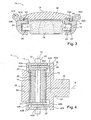
- the common plane here corresponds to the cutting plane "P3" of the figure 2 .
- Each rail 58A, 58B has a cross section in the shape of "U" which is limited transversely by a first 60 and second 62 radial walls, respectively upstream and downstream, so as to maintain transversely each lug 56A, 56B inside the rail 58A, 58B associated.
- the lug 56A, 56B is slidably mounted in the rail 58A, 58B with a transverse clearance.
- Each rail 58A, 58B comprises elastic return means of the lug 56A, 56B associated to a position centered transversely relative to the rail 58A, 58B in order to maintain a transverse clearance between the lug 56A, 56B and each of the walls 60, 62 of the rail 58A, 58B.
- the elastic return means comprise radial radial blades 64 which are interposed transversely between one of the radial walls 60, 62 of the rail 58A, 58B and the lug 56A, 56B associated.
- each rail 58A, 58B comprises an elastic blade 64.
- Each rail 58A, 58B being located near a slide shoe 22, it is possible here to achieve the elastic blade 64 integral with the leaf spring 24 of the associated slide 22.
- the leaf spring 24 has a shape of "S" whose lower curve matches the shape of the slide 22, while the upper curve is shaped so that the upper end of the "S” is interposed between the first wall 60 of the second rail 58B and the second lug 56B, or between the second wall 62 of the first rail 58A and the first lug 56A.
- the transverse deformation of the second slide 44B causes the transverse deformation of the second rail 58B.
- the first wall 60 of the second rail 58B is thus brought into abutment against the second lug 56B.
- first slideway 44A brings the second wall 62 of the first rail 58A into contact with the first lug 56A.
- the first 56A and second 56B lugs each being in contact with two opposite walls 60, 62 by means of the elastic blades 64, they contain and limit the deformation of the fixed yoke 14.
- Part of the transverse force applied by the skids 16, 18 against the second slide 44B is communicated directly to the second slide 44B through the stirrup 28 in the direction of the common plane of the pins 56A, 56B, as shown in thick broken lines 66 at the figure 4 .
- the disk brake 10 produced according to the teachings of the invention thus makes it possible to substantially reduce and distribute in a balanced manner the deformation of the fixed yoke 14, and in particular to keep the first 44A and second 44B substantially parallel slides.
- the forces exerted on the outer free end 42A, 428 of each guide axis 40A, 40B are thus substantially reduced.
- the stirrup 28 When the pads 16, 18 are no longer applied to the opposite faces 30, 32 of the disc 12, the stirrup 28 must be able to slide towards a rest position. The transverse force of the pads 16, 18 being released, the pins 56A, 56B are recalled to a transversely centered position in the rails 58A, 58B associated by the elastic blades 64. Thus, the lugs 56A, 56B slide axially without friction in the rails 58A, 58B. The axial sliding movement of the stirrup 28 is therefore not slowed down.
- the lug 56A, 56B has an axial length sufficiently small to promote the sliding of the lug 56A, 56B in the rail 58A, 58B.
- the lug 56A, 56B must maintain a deformation resistance sufficient to withstand the force transmitted by the pads 16, 18 without being deformed.
- the invention advantageously makes it possible to balance the forces exerted on the yoke 14, when the brake pads 18 are applied on either side of the disc 12, by transmitting a part of the transverse force from the second slide 44B to the first slide 44A directly via the bracket 28, without passing through the guide pins 40A, 40B.
- the yoke 14 is thus little or not deformed, and the guide pins 40A, 40B remain substantially parallel to each other during braking, which promotes the axial sliding of the yoke 28 relative to the yoke 14.
Landscapes
- Engineering & Computer Science (AREA)
- General Engineering & Computer Science (AREA)
- Mechanical Engineering (AREA)
- Braking Arrangements (AREA)
Claims (8)
- Scheibenbremse (10) für Kraftfahrzeug, vom Typ, der einen festen Halter (14) aufweist, in welchem ein Innenbremsklotz (16) und ein Außenbremsklotz (18) axial verschiebbar angebracht sind, die von einem Sattel (28) gegen die zueinander entgegengesetzten Innen- (30) und Außenseite (30) einer Scheibe (12) gedrückt werden können, die um eine Achse (B) drehend angebracht ist, vom Typ, in welchem der Sattel (28) bezüglich des Halters (14) mittels einer axialen parallelen ersten Führungsachse (40A) und zweiten Führungsachse (40B), die parallel sind, axial verschiebbar ist, vom Typ in welchen ein Innenfuß (48A, 48B) jeder Führungsachse (40A, 40B) am Sattel (28) befestigt ist, und vom Typ, in welchem das frei Außenende (42A, 42B) jeder Führungsachse (40A, 40B) in einer ersten und zweiten axialen Führung (44A, 44B) gleitend angebracht sind, die dem festen Halters (14) zugeordnet sind, wobei die erste (44A) und zweite (44b) Führung aufwärts bzw. abwärts der Drehrichtung (T) der Scheibe (12) angeordnet ist, und vom Typ, in welchem die Bremsklötze (16, 18), wenn sie gegen die Scheibe angedrückt sind, eine Querkraft gegen die zweite Führung (44b) ausüben, wobei die Kraft auf die erste entgegengesetzte Führung (44A) über die erste zugeordnete Führungsachse (40B) und die zweite zugeordnete Führungsachse (40A) des verschiebbaren Sattels (28) übertragen wird,
dadurch gekennzeichnet, dass der verschiebbare Sattel (28) Mittel (56A, 56B, 58A, 58B) aufweist, um einen Teil der Kraft von der zweiten Führung (44B) zur ersten Führung (44A) direkt zu übertragen, um die Verformung des festen Halters (14) zu verteilen. - Scheibenbremse (10) nach dem vorhergehenden Anspruch, dadurch gekennzeichnet, dass der Sattel (28) an jedem seiner Querenden mindestens einen ersten (56A) und zweiten (56B) radialen Endvorsprung aufweist, die dazu bestimmt sind, axial in einer axialen ersten Schiene (58A) bzw. zweiten Schiene, die dem festen Halter (14) zugeordnet sind, zu gleiten.
- Scheibenbremse (10) nach dem vorhergehenden Anspruch, dadurch gekennzeichnet, dass sich jede Schiene (58A, 58B) jeweils in der Nähe der ersten Führung (44A) bzw. der zweiten Führung (44B) befindet.
- Scheibenbremse (10) nach einem der Ansprüche 2 oder 3, dadurch gekennzeichnet, dass die Nasen (56A, 56B) in einer gemeinsamen Ebene (P3) angeordnet sind, die zur Außenseite (32) der Scheibe (12) parallel und in der Nähe der freien Enden (42A, 42B) der Führungsachsen (40A, 40B) liegt, um die auf das freie Außenende (42A, 42B) jeder Führungsachse (40, 40B) ausgeübten Kräfte zu reduzieren.
- Scheibenbremse (10) nach einem der Ansprüche 2 bis 4, dadurch gekennzeichnet, dass die Nasen (56A, 56B) in den Schienen (58A, 58B) mit einem Querspiel gleitend angebracht sind.
- Scheibenbremse (10) nach dem vorhergehenden Anspruch, dadurch gekennzeichnet, dass jede Schiene (58A, 58B) Mittel (64) zum elastischen Rückstellen der zugeordneten Nase (56A, 56B) zu einer quer zentrierten Stellung bezüglich der Schiene (58A, 58B) aufweist.
- Scheibenbremse (10) nach dem vorhergehenden Anspruch, dadurch gekennzeichnet, dass die elastischen Rückstellmittel elastische radiale Blattfeder (64) aufweisen, die zwischen der radialen Wand (60, 62) der Schiene (58A, 58B) und der zugeordneten Nase (56A, 56B) eingesetzt sind.
- Scheibenbremse (10) nach dem vorhergehenden Anspruch, dadurch gekennzeichnet, dass die Bremsklötze (16, 18) bezüglich des festen Halters (14) über elastische, als axiale Schieber angeformte Blattfedern (24) verschiebbar geführt sind, und dass jedes elastische Rückstellmittel (64) mit dem zugeordneten Bremsklotzschieber (24) einstückig ausgebildet ist.
Applications Claiming Priority (1)
| Application Number | Priority Date | Filing Date | Title |
|---|---|---|---|
| FR0407574A FR2872875B1 (fr) | 2004-07-07 | 2004-07-07 | Frein a disque a etrier flottant comportant des moyens pour eviter la deformation de la chape lors des freinages |
Publications (2)
| Publication Number | Publication Date |
|---|---|
| EP1614924A1 EP1614924A1 (de) | 2006-01-11 |
| EP1614924B1 true EP1614924B1 (de) | 2011-04-06 |
Family
ID=34947425
Family Applications (1)
| Application Number | Title | Priority Date | Filing Date |
|---|---|---|---|
| EP05014441A Ceased EP1614924B1 (de) | 2004-07-07 | 2005-07-04 | Schwimmsattel-Scheibenbremse mit Mittel zum Vermeiden der Formveränderung des Bremsträgers während eines Bremsvorgangs |
Country Status (4)
| Country | Link |
|---|---|
| EP (1) | EP1614924B1 (de) |
| AT (1) | ATE504757T1 (de) |
| DE (1) | DE602005027289D1 (de) |
| FR (1) | FR2872875B1 (de) |
Family Cites Families (3)
| Publication number | Priority date | Publication date | Assignee | Title |
|---|---|---|---|---|
| DE2750337C2 (de) * | 1977-11-10 | 1985-09-05 | Alfred Teves Gmbh, 6000 Frankfurt | Teilbelagscheibenbremse, insbesondere für Kraftfahrzeuge |
| FR2747751B1 (fr) * | 1996-04-22 | 1998-05-22 | Bosch Syst Freinage | Frein a disque a couples parasites reduits |
| DE10238735A1 (de) * | 2002-08-23 | 2004-03-11 | Continental Teves Ag & Co. Ohg | Schwimmsattel-Scheibenbremse mit Bremshalter |
-
2004
- 2004-07-07 FR FR0407574A patent/FR2872875B1/fr not_active Expired - Fee Related
-
2005
- 2005-07-04 EP EP05014441A patent/EP1614924B1/de not_active Ceased
- 2005-07-04 DE DE602005027289T patent/DE602005027289D1/de not_active Expired - Lifetime
- 2005-07-04 AT AT05014441T patent/ATE504757T1/de not_active IP Right Cessation
Also Published As
| Publication number | Publication date |
|---|---|
| ATE504757T1 (de) | 2011-04-15 |
| FR2872875A1 (fr) | 2006-01-13 |
| DE602005027289D1 (de) | 2011-05-19 |
| EP1614924A1 (de) | 2006-01-11 |
| FR2872875B1 (fr) | 2007-10-05 |
Similar Documents
| Publication | Publication Date | Title |
|---|---|---|
| EP3253984B1 (de) | Scheibenbremse mit mindestens einer feder für die elastische rückstellung eines bremsbelags, elastische rückstellfeder und ersatzkit | |
| EP3265687B1 (de) | Scheibenbremse mit mindestens einer elastischen rückstellfeder eines bremsbelages, elastische rückstellfeder führungsschiene und ersatzkit | |
| EP2792899B1 (de) | Scheibenbremse, die mit elastischen rückstellmitteln der bremsbacken und mit mitteln zum beseitigen des verschleissspiels der bremsbacken durch plastische verformung ausgestattet ist | |
| EP2791538B1 (de) | Scheibenbremsbelagführung und scheibenbremse mit einer derartigen führung | |
| EP3020996B1 (de) | Schwimmsattelbremse, die eine zentrale elastische rückholfeder eines externen bremsbelags umfasst, die ausgleichsmittel des verschleissspiels umfasst, feder und ersatzteilkit | |
| EP3006763B1 (de) | Elastische rückholfeder eines bremsbelags, die ausgleichsmittel des verschleissspiels umfasst, scheibenbremse und ersatzteilkit | |
| WO2013087868A1 (fr) | Organe de guidage a ressort d'un patin de frein a disque et frein a disque equipe de tels organes de guidage | |
| WO2006040428A1 (fr) | Element de friction et frein a disque | |
| EP1447585B1 (de) | Reibelement sowie hiermit versehene Scheibenbremse für Kraftfahrzeuge | |
| EP1933054B1 (de) | Scheibenbremse, die mit elastischen Rückholvorrichtungen für den Bremsbelagträger in seiner Ruheposition ausgestattet ist | |
| WO2016135117A1 (fr) | Frein a disque comportant au moins un ressort de rappel elastique d'un patin de freinage, ressort de rappel elastique, kit de remplacement et procede de montage | |
| FR2912194A1 (fr) | Frein a disque muni d'un dispositif pour ecarter les plaquettes du disque en l'absence de sollicitation du systeme de freinage | |
| WO2020260098A1 (fr) | Frein à disque comportant au moins un ressort de rappel élastique d'un patin de freinage, ressort de rappel élastique, kit de remplacement et procédé de montage | |
| EP1614924A1 (de) | Schwimmsattel-Scheibenbremse mit Mittel zum Vermeiden der Formveränderung des Bremsträgers während eines Bremsvorgangs | |
| WO2016135118A1 (fr) | Frein a disque comportant au moins un ressort perfectionne de rappel elastique d'un patin de freinage, ressort de rappel elastique, kit de remplacement et procede de montage | |
| FR2905155A1 (fr) | Frein a disque comportant un axe dont une portee presente une section de profil non circulaire | |
| EP3265688B1 (de) | Bremsscheibe mit mindestens einer verbesserten elastischen rückstellfeder eines bremsbelages, elastische rückstellfeder und austauschkit | |
| EP1914437A1 (de) | Scheibenbremse mit rückstellendem Dämpfungsblech | |
| EP2072849A1 (de) | Scheibenbremse, die Bremsbelagträger mit differenzierten Reibungskoeffizienten umfasst | |
| FR2747751A1 (fr) | Frein a disque a couples parasites reduits |
Legal Events
| Date | Code | Title | Description |
|---|---|---|---|
| PUAI | Public reference made under article 153(3) epc to a published international application that has entered the european phase |
Free format text: ORIGINAL CODE: 0009012 |
|
| AK | Designated contracting states |
Kind code of ref document: A1 Designated state(s): AT BE BG CH CY CZ DE DK EE ES FI FR GB GR HU IE IS IT LI LT LU LV MC NL PL PT RO SE SI SK TR |
|
| AX | Request for extension of the european patent |
Extension state: AL BA HR MK YU |
|
| 17P | Request for examination filed |
Effective date: 20060711 |
|
| 17Q | First examination report despatched |
Effective date: 20060810 |
|
| AKX | Designation fees paid |
Designated state(s): AT BE BG CH CY CZ DE DK EE ES FI FR GB GR HU IE IS IT LI LT LU LV MC NL PL PT RO SE SI SK TR |
|
| GRAP | Despatch of communication of intention to grant a patent |
Free format text: ORIGINAL CODE: EPIDOSNIGR1 |
|
| GRAS | Grant fee paid |
Free format text: ORIGINAL CODE: EPIDOSNIGR3 |
|
| GRAA | (expected) grant |
Free format text: ORIGINAL CODE: 0009210 |
|
| AK | Designated contracting states |
Kind code of ref document: B1 Designated state(s): AT BE BG CH CY CZ DE DK EE ES FI FR GB GR HU IE IS IT LI LT LU LV MC NL PL PT RO SE SI SK TR |
|
| REG | Reference to a national code |
Ref country code: GB Ref legal event code: FG4D Free format text: NOT ENGLISH |
|
| REG | Reference to a national code |
Ref country code: CH Ref legal event code: EP |
|
| REG | Reference to a national code |
Ref country code: IE Ref legal event code: FG4D |
|
| REF | Corresponds to: |
Ref document number: 602005027289 Country of ref document: DE Date of ref document: 20110519 Kind code of ref document: P |
|
| REG | Reference to a national code |
Ref country code: DE Ref legal event code: R096 Ref document number: 602005027289 Country of ref document: DE Effective date: 20110519 |
|
| REG | Reference to a national code |
Ref country code: NL Ref legal event code: VDEP Effective date: 20110406 |
|
| PG25 | Lapsed in a contracting state [announced via postgrant information from national office to epo] |
Ref country code: SI Free format text: LAPSE BECAUSE OF FAILURE TO SUBMIT A TRANSLATION OF THE DESCRIPTION OR TO PAY THE FEE WITHIN THE PRESCRIBED TIME-LIMIT Effective date: 20110406 |
|
| LTIE | Lt: invalidation of european patent or patent extension |
Effective date: 20110406 |
|
| REG | Reference to a national code |
Ref country code: IE Ref legal event code: FD4D |
|
| PG25 | Lapsed in a contracting state [announced via postgrant information from national office to epo] |
Ref country code: LT Free format text: LAPSE BECAUSE OF FAILURE TO SUBMIT A TRANSLATION OF THE DESCRIPTION OR TO PAY THE FEE WITHIN THE PRESCRIBED TIME-LIMIT Effective date: 20110406 Ref country code: PT Free format text: LAPSE BECAUSE OF FAILURE TO SUBMIT A TRANSLATION OF THE DESCRIPTION OR TO PAY THE FEE WITHIN THE PRESCRIBED TIME-LIMIT Effective date: 20110808 Ref country code: SE Free format text: LAPSE BECAUSE OF FAILURE TO SUBMIT A TRANSLATION OF THE DESCRIPTION OR TO PAY THE FEE WITHIN THE PRESCRIBED TIME-LIMIT Effective date: 20110406 |
|
| PG25 | Lapsed in a contracting state [announced via postgrant information from national office to epo] |
Ref country code: IS Free format text: LAPSE BECAUSE OF FAILURE TO SUBMIT A TRANSLATION OF THE DESCRIPTION OR TO PAY THE FEE WITHIN THE PRESCRIBED TIME-LIMIT Effective date: 20110806 Ref country code: AT Free format text: LAPSE BECAUSE OF FAILURE TO SUBMIT A TRANSLATION OF THE DESCRIPTION OR TO PAY THE FEE WITHIN THE PRESCRIBED TIME-LIMIT Effective date: 20110406 Ref country code: ES Free format text: LAPSE BECAUSE OF FAILURE TO SUBMIT A TRANSLATION OF THE DESCRIPTION OR TO PAY THE FEE WITHIN THE PRESCRIBED TIME-LIMIT Effective date: 20110717 Ref country code: CY Free format text: LAPSE BECAUSE OF FAILURE TO SUBMIT A TRANSLATION OF THE DESCRIPTION OR TO PAY THE FEE WITHIN THE PRESCRIBED TIME-LIMIT Effective date: 20110406 Ref country code: GR Free format text: LAPSE BECAUSE OF FAILURE TO SUBMIT A TRANSLATION OF THE DESCRIPTION OR TO PAY THE FEE WITHIN THE PRESCRIBED TIME-LIMIT Effective date: 20110707 Ref country code: LV Free format text: LAPSE BECAUSE OF FAILURE TO SUBMIT A TRANSLATION OF THE DESCRIPTION OR TO PAY THE FEE WITHIN THE PRESCRIBED TIME-LIMIT Effective date: 20110406 Ref country code: FI Free format text: LAPSE BECAUSE OF FAILURE TO SUBMIT A TRANSLATION OF THE DESCRIPTION OR TO PAY THE FEE WITHIN THE PRESCRIBED TIME-LIMIT Effective date: 20110406 |
|
| PG25 | Lapsed in a contracting state [announced via postgrant information from national office to epo] |
Ref country code: NL Free format text: LAPSE BECAUSE OF FAILURE TO SUBMIT A TRANSLATION OF THE DESCRIPTION OR TO PAY THE FEE WITHIN THE PRESCRIBED TIME-LIMIT Effective date: 20110406 |
|
| BERE | Be: lapsed |
Owner name: ROBERT BOSCH G.M.B.H. Effective date: 20110731 |
|
| PG25 | Lapsed in a contracting state [announced via postgrant information from national office to epo] |
Ref country code: IE Free format text: LAPSE BECAUSE OF FAILURE TO SUBMIT A TRANSLATION OF THE DESCRIPTION OR TO PAY THE FEE WITHIN THE PRESCRIBED TIME-LIMIT Effective date: 20110406 Ref country code: CZ Free format text: LAPSE BECAUSE OF FAILURE TO SUBMIT A TRANSLATION OF THE DESCRIPTION OR TO PAY THE FEE WITHIN THE PRESCRIBED TIME-LIMIT Effective date: 20110406 Ref country code: EE Free format text: LAPSE BECAUSE OF FAILURE TO SUBMIT A TRANSLATION OF THE DESCRIPTION OR TO PAY THE FEE WITHIN THE PRESCRIBED TIME-LIMIT Effective date: 20110406 |
|
| PLBE | No opposition filed within time limit |
Free format text: ORIGINAL CODE: 0009261 |
|
| STAA | Information on the status of an ep patent application or granted ep patent |
Free format text: STATUS: NO OPPOSITION FILED WITHIN TIME LIMIT |
|
| PG25 | Lapsed in a contracting state [announced via postgrant information from national office to epo] |
Ref country code: RO Free format text: LAPSE BECAUSE OF FAILURE TO SUBMIT A TRANSLATION OF THE DESCRIPTION OR TO PAY THE FEE WITHIN THE PRESCRIBED TIME-LIMIT Effective date: 20110406 Ref country code: DK Free format text: LAPSE BECAUSE OF FAILURE TO SUBMIT A TRANSLATION OF THE DESCRIPTION OR TO PAY THE FEE WITHIN THE PRESCRIBED TIME-LIMIT Effective date: 20110406 Ref country code: PL Free format text: LAPSE BECAUSE OF FAILURE TO SUBMIT A TRANSLATION OF THE DESCRIPTION OR TO PAY THE FEE WITHIN THE PRESCRIBED TIME-LIMIT Effective date: 20110406 Ref country code: SK Free format text: LAPSE BECAUSE OF FAILURE TO SUBMIT A TRANSLATION OF THE DESCRIPTION OR TO PAY THE FEE WITHIN THE PRESCRIBED TIME-LIMIT Effective date: 20110406 Ref country code: MC Free format text: LAPSE BECAUSE OF NON-PAYMENT OF DUE FEES Effective date: 20110731 |
|
| REG | Reference to a national code |
Ref country code: CH Ref legal event code: PL |
|
| 26N | No opposition filed |
Effective date: 20120110 |
|
| PG25 | Lapsed in a contracting state [announced via postgrant information from national office to epo] |
Ref country code: CH Free format text: LAPSE BECAUSE OF NON-PAYMENT OF DUE FEES Effective date: 20110731 Ref country code: BE Free format text: LAPSE BECAUSE OF NON-PAYMENT OF DUE FEES Effective date: 20110731 Ref country code: LI Free format text: LAPSE BECAUSE OF NON-PAYMENT OF DUE FEES Effective date: 20110731 |
|
| REG | Reference to a national code |
Ref country code: DE Ref legal event code: R097 Ref document number: 602005027289 Country of ref document: DE Effective date: 20120110 |
|
| PG25 | Lapsed in a contracting state [announced via postgrant information from national office to epo] |
Ref country code: LU Free format text: LAPSE BECAUSE OF NON-PAYMENT OF DUE FEES Effective date: 20110704 |
|
| PG25 | Lapsed in a contracting state [announced via postgrant information from national office to epo] |
Ref country code: BG Free format text: LAPSE BECAUSE OF FAILURE TO SUBMIT A TRANSLATION OF THE DESCRIPTION OR TO PAY THE FEE WITHIN THE PRESCRIBED TIME-LIMIT Effective date: 20110706 |
|
| PG25 | Lapsed in a contracting state [announced via postgrant information from national office to epo] |
Ref country code: TR Free format text: LAPSE BECAUSE OF FAILURE TO SUBMIT A TRANSLATION OF THE DESCRIPTION OR TO PAY THE FEE WITHIN THE PRESCRIBED TIME-LIMIT Effective date: 20110406 |
|
| PG25 | Lapsed in a contracting state [announced via postgrant information from national office to epo] |
Ref country code: HU Free format text: LAPSE BECAUSE OF FAILURE TO SUBMIT A TRANSLATION OF THE DESCRIPTION OR TO PAY THE FEE WITHIN THE PRESCRIBED TIME-LIMIT Effective date: 20110406 |
|
| PG25 | Lapsed in a contracting state [announced via postgrant information from national office to epo] |
Ref country code: IT Free format text: LAPSE BECAUSE OF FAILURE TO SUBMIT A TRANSLATION OF THE DESCRIPTION OR TO PAY THE FEE WITHIN THE PRESCRIBED TIME-LIMIT Effective date: 20110406 |
|
| PGFP | Annual fee paid to national office [announced via postgrant information from national office to epo] |
Ref country code: GB Payment date: 20140624 Year of fee payment: 10 |
|
| GBPC | Gb: european patent ceased through non-payment of renewal fee |
Effective date: 20150704 |
|
| PG25 | Lapsed in a contracting state [announced via postgrant information from national office to epo] |
Ref country code: GB Free format text: LAPSE BECAUSE OF NON-PAYMENT OF DUE FEES Effective date: 20150704 |
|
| REG | Reference to a national code |
Ref country code: FR Ref legal event code: PLFP Year of fee payment: 12 |
|
| REG | Reference to a national code |
Ref country code: FR Ref legal event code: PLFP Year of fee payment: 13 |
|
| REG | Reference to a national code |
Ref country code: FR Ref legal event code: PLFP Year of fee payment: 14 |
|
| PGFP | Annual fee paid to national office [announced via postgrant information from national office to epo] |
Ref country code: DE Payment date: 20210622 Year of fee payment: 17 |
|
| PGFP | Annual fee paid to national office [announced via postgrant information from national office to epo] |
Ref country code: FR Payment date: 20220622 Year of fee payment: 18 |
|
| REG | Reference to a national code |
Ref country code: DE Ref legal event code: R119 Ref document number: 602005027289 Country of ref document: DE |
|
| PG25 | Lapsed in a contracting state [announced via postgrant information from national office to epo] |
Ref country code: DE Free format text: LAPSE BECAUSE OF NON-PAYMENT OF DUE FEES Effective date: 20230201 |
|
| PG25 | Lapsed in a contracting state [announced via postgrant information from national office to epo] |
Ref country code: FR Free format text: LAPSE BECAUSE OF NON-PAYMENT OF DUE FEES Effective date: 20230731 |