EP1614929A1 - Garniture d'étanhéité et de guidage - Google Patents
Garniture d'étanhéité et de guidage Download PDFInfo
- Publication number
- EP1614929A1 EP1614929A1 EP05013066A EP05013066A EP1614929A1 EP 1614929 A1 EP1614929 A1 EP 1614929A1 EP 05013066 A EP05013066 A EP 05013066A EP 05013066 A EP05013066 A EP 05013066A EP 1614929 A1 EP1614929 A1 EP 1614929A1
- Authority
- EP
- European Patent Office
- Prior art keywords
- seal
- pressure
- elastomeric element
- sealing
- piston rod
- Prior art date
- Legal status (The legal status is an assumption and is not a legal conclusion. Google has not performed a legal analysis and makes no representation as to the accuracy of the status listed.)
- Granted
Links
Images


Classifications
-
- F—MECHANICAL ENGINEERING; LIGHTING; HEATING; WEAPONS; BLASTING
- F16—ENGINEERING ELEMENTS AND UNITS; GENERAL MEASURES FOR PRODUCING AND MAINTAINING EFFECTIVE FUNCTIONING OF MACHINES OR INSTALLATIONS; THERMAL INSULATION IN GENERAL
- F16F—SPRINGS; SHOCK-ABSORBERS; MEANS FOR DAMPING VIBRATION
- F16F9/00—Springs, vibration-dampers, shock-absorbers, or similarly-constructed movement-dampers using a fluid or the equivalent as damping medium
- F16F9/32—Details
- F16F9/36—Special sealings, including sealings or guides for piston-rods
- F16F9/362—Combination of sealing and guide arrangements for piston rods
Definitions
- the invention relates to a seal and guide package for shock absorbers.
- hydraulic shock absorbers are on the one hand sealed sealing
- these seal and guide packages are used to guide the piston rod in its oscillating movement.
- the seal and guide package is on the one hand sealingly against the inner wall of the shock absorber tube, while on the other hand comprises a seal which bears sealingly against the surface of the oscillatingly moving piston rod.
- a sealing and guiding element is known from DE 199 38 084 A1, which has a guide sleeve displaceable over a partial region of the stroke movement of the piston rod, which is connected to a spring element supported on a housing or a bearing body.
- the sealing element coming into contact with the piston rod is arranged to be movable together with the guide sleeve. In this way, the effects of friction, which are effective between the sealing element and the piston rod and which lead to impairment of ride comfort, should be avoided.
- the friction between the sealing element and the piston rod can therefore lead to impairment of ride comfort, for example, because a desired compression movement of the Vehicle wheel, especially with small impact loads, avoided or delayed due to an adhesion of the guide sleeve or the damping element on the piston rod (so-called stick-slip effect).
- a avoided in this way or delayed compression movement of the vehicle wheel has an introduction of particular undamped and / or unsprung disturbing forces in the vehicle carrier result.
- This solution is relatively complicated because relevant components of the entire seal and guide package must be arranged to be movable.
- a further disadvantage is that inevitably a movement-related wear is associated with the mobility of the guide sleeve.
- the invention has for its object to provide a seal and guide package for shock absorbers available, which minimizes or completely avoids the negative effects of the stick-slip effect, so that the ride comfort is improved.
- an elastomeric element encloses the cylindrical seal, which is in sealing contact with the piston rod.
- the elastomer element is designed in a particularly advantageous manner, so that the seal is optimally elastically supported in the axial direction.
- the elastomer element has a further shorter lobe, which on the lateral surface of the cylindrical seal acts and biases the seal against the piston rod. This bias ensures that the gasket is always sealing against the piston rod surface.
- supporting discs are arranged between the end faces of the seal and the lugs of the elastomeric element supporting them.
- These support disks may for example consist of a steel material.
- the sealing and guiding assembly comprises a substantially cylindrical base body having a recess into which the elastomeric element is inserted.
- the recess in the base body is dimensioned in relation to the radial position of the piston rod so that upon insertion of the elastomeric element in the body or when inserting the seal and guide package in the shock absorber, the elastomeric element is compressed in the radial direction, so that a radial bias the seal against the piston rod takes place.
- the axial bias of the elastomeric element is in this embodiment of the invention achieved by a lid which is mounted on the body under axial compression of the elastomeric element.
- the elastomer element is compressed in the axial direction, so that acts from the elastomeric element, a bias in the axial direction of the seal.
- pressure channels are present in which there is a pressurized fluid in the operating state.
- a pressure on the damper interior remote from the end face of the elastomeric element is passed, which counteracts the pressure from the piston rod side working space of the damper.
- the pressurized fluid which may be, for example, the pressurized damping fluid of the shock absorber, acts either directly on the elastomeric element, or the action of the pressure on the elastomeric element is indirectly mediated, with interposition of one or more further support elements. indirectly transferred to the elastomeric element.
- the internal pressure of the damper is balanced, which would otherwise push the elastomer element together with the seal upwards.
- a complete pressure relief of the elastomer element is achieved via the pressure channels, so that it is unloaded, i. without having to record an axial compressive load, sitting in the seal and guide package.
- the axial and radial bias of the elastomeric member is achieved in the second embodiment in the same manner as in the first embodiment.
- the bias of the elastomeric element is also achieved according to the first embodiment of the invention, formed ordered pressure channel, ie the radial and axial bias of the elastomeric element is carried out in this third embodiment of the invention analogous to the first embodiment of the invention described above.
- a pressure channel which is connected to a pressurized gas space, so that in the pressure channel, a pressurized gas is effective.
- This pressurized gas may act directly or indirectly on the elastomeric element.
- the third embodiment of the invention is particularly advantageous if the shock absorber is part of an air spring strut.
- the pressure chamber of the air spring can be used to provide the pressurized gas for pressure relief.
- FIG. 1 an inventive seal and guide package is shown in axial half section.
- the sealing and guiding package comprises a basic body 1, which at its upper end in the region of the piston rod has a recess into which an elastomer element 7 is inserted.
- This elastomer element 7 encloses a seal 6, which is in contact with the surface of the piston rod 10.
- the elastomer element 7 has radially extending tabs 7a, 7b, which cover the end faces 6a, 6b of the seal 6, so that the Seal 6 is elastically supported in the axial direction.
- support disks 8, 9 are arranged so that the lobes 7a, 7b of the elastomer element 7 are not directly in contact with the seal, but the elastic support of the seal indirectly with the interposition of the support disks. 8 , 9 takes place.
- the support discs 8, 9 are not mandatory in the invention. With a suitable design and design of the elastomer element, for example, in terms of shape and / or an inhomogeneous density distribution, they can be omitted.
- the flap 7c is dimensioned in terms of its radial extent so that it exerts a force on the lateral surface of the cylindrical seal 6, so that it is held in the inserted state under radial bias. In this way, the elastomer element 7 is biased in both the axial and in the radial direction.
- the seal is protected against tilting and tilting and held in their intended position.
- the design of the elastomer element 7 with the two outer longer lobes 7a, 7b supports the stability of the seal.
- the short lug 7c biases the seal 6 on the piston rod 10 and, if the possibility for pressurization is created constructively, replaces the two O-rings of the so-called stepseal seals known from the prior art (see Patent DE 198 36 286).
- the element 7c operates in accordance with the O-rings shown in the aforementioned patent by the pressure of the seal 6 is increased pressure-dependent on the piston rod 10 at a pressurization by an elastic deformation. This is achieved by the appropriate shaping as well as the elastic properties and the incompressibility of the element 7c.
- the main body of the seal and guide package is formed in several parts.
- the components 1.1, 1.2 and 1.3 form the body of the seal and guide package.
- O-ring seals 13, 14, the individual components of the multi-part main body are sealed against each other.
- the seal between the base body and the shock absorber tube 11 takes place through the O-ring 3.
- the main body component 1.1 has a groove in which a guide band 2 for centering the piston rod is arranged, which is in contact with the piston rod 10.
- This guide band is usually made in a known manner from the material PTFE, wherein the PTFE may contain different fillers.
- the guide band serves to receive transverse forces acting on the piston rod.
- pressure channels 12 are formed, is guided by the under pressure in the operating state damping fluid.
- This pressurized damping fluid exerts pressure on the elastomer element 7 from above, which leads to an axial prestressing of the elastomer element 7 and compensates for the internal pressure of the damper.
- the seal 6 is thus not pressurized on one side and thus runs pressure-balanced.
- the pressurized surfaces must be adjusted and designed accordingly. The movement of the elastomer is thus ensured in both directions.
- the upper horizontal pressure channel 12 is formed in this embodiment of the invention between the component 1.3 of the base body and the elastomer element 7.
- the O-ring 14 seals the base body components 1.1 and 1.2 to the outside.
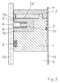
- a third embodiment of the invention is shown.
- the base body 1 of the seal and guide package is constructed substantially the same as in the illustrated in Fig. 1 first embodiment.
- the radial bias of the elastomeric element 7 is thus carried out in the same manner as above to Fig. 1.
- a pressure channel 12 is provided in this third embodiment of the invention, which is formed between a component 1.3, which belongs to the base body 1, and the elastomer element 7.
- This pressure channel 12 is in communication with a gas pressure chamber, not shown in Fig. 3, which may be, for example, the pressure chamber of an air spring.
- the pressurized gas in this gas pressure chamber is thus also in guided the pressure channel 12 and acts directly in the axial direction of the elastomer element 7 a.
- the high external pressure compensates for the pressure which acts on the elastomer element from below, ie from the working space.
- the seal can be operated pressure-balanced and its movement in both axial directions is ensured.
- This structural design of the seal and guide package has the advantage that in a structurally simple manner existing in an air spring strut pressure chamber of the air spring can be exploited to effect the pressure equalization of the elastomer element 7.
Landscapes
- Engineering & Computer Science (AREA)
- General Engineering & Computer Science (AREA)
- Mechanical Engineering (AREA)
- Fluid-Damping Devices (AREA)
Applications Claiming Priority (1)
| Application Number | Priority Date | Filing Date | Title |
|---|---|---|---|
| DE102004033214A DE102004033214B3 (de) | 2004-07-09 | 2004-07-09 | Dichtungs- und Führungspaket |
Publications (2)
| Publication Number | Publication Date |
|---|---|
| EP1614929A1 true EP1614929A1 (fr) | 2006-01-11 |
| EP1614929B1 EP1614929B1 (fr) | 2006-08-23 |
Family
ID=34982372
Family Applications (1)
| Application Number | Title | Priority Date | Filing Date |
|---|---|---|---|
| EP05013066A Expired - Lifetime EP1614929B1 (fr) | 2004-07-09 | 2005-06-17 | Garniture d'étanhéité et de guidage |
Country Status (4)
| Country | Link |
|---|---|
| US (1) | US7311182B2 (fr) |
| EP (1) | EP1614929B1 (fr) |
| DE (2) | DE102004033214B3 (fr) |
| ES (1) | ES2267084T3 (fr) |
Families Citing this family (4)
| Publication number | Priority date | Publication date | Assignee | Title |
|---|---|---|---|---|
| DE102008024039A1 (de) * | 2008-05-16 | 2009-11-26 | Zf Friedrichshafen Ag | Kolben-Zylinder-Aggregat |
| DE102008041995A1 (de) * | 2008-09-11 | 2009-12-10 | Zf Friedrichshafen Ag | Kolbenstangenführung für einen Einrohrschwingungsdämpfer |
| US8403334B2 (en) * | 2009-01-07 | 2013-03-26 | Mahle Engine Components Usa, Inc. | Multi-rail piston ring |
| DE102016217117A1 (de) | 2016-09-08 | 2016-12-01 | Zf Friedrichshafen Ag | Frequenzselektive Dämpfventilanordnung |
Citations (4)
| Publication number | Priority date | Publication date | Assignee | Title |
|---|---|---|---|---|
| FR1407890A (fr) * | 1964-06-22 | 1965-08-06 | Joint d'étanchéité | |
| US4053166A (en) * | 1975-12-08 | 1977-10-11 | Halogen Insulator & Seal Corporation | Two-piece seal |
| DE19938084A1 (de) | 1998-12-11 | 2000-07-06 | Daimler Chrysler Ag | Führungslager im Zusammenhang mit einem Druckzylinder, insbesondere Dämpfungselement für Kraftfahrzeuge |
| EP1353085A2 (fr) * | 2002-04-09 | 2003-10-15 | Busak + Shamban GmbH | Dispositif d'étanchéité, en particulier pour un système à ressort pneumatique |
Family Cites Families (12)
| Publication number | Priority date | Publication date | Assignee | Title |
|---|---|---|---|---|
| US2368380A (en) * | 1942-09-24 | 1945-01-30 | John W Ruzicka | Shaft seal |
| US2483827A (en) * | 1945-09-28 | 1949-10-04 | Guiler Cameron | Sealing device |
| US2974983A (en) * | 1956-02-23 | 1961-03-14 | Equi Flex Products Inc | Device for wiping or scraping a working member |
| US3918726A (en) * | 1974-01-28 | 1975-11-11 | Jack M Kramer | Flexible seal ring |
| GB1581971A (en) * | 1977-02-22 | 1980-12-31 | Honda Motor Co Ltd | Shock absorbers |
| DE7705770U1 (de) * | 1977-02-25 | 1977-06-30 | Boge Gmbh, 5208 Eitorf | Dichtring zur Abdichtung einer Kolbenstange von Teleskopschwingungsdämpfern, insbesondere für Kraftfahrzeuge |
| DE3202705C2 (de) * | 1982-01-28 | 1984-11-22 | August Bilstein GmbH & Co KG, 5828 Ennepetal | Hydropneumatischer Schwingungsdämpfer für Kraftfahrzeuge |
| DE3529422A1 (de) * | 1985-08-16 | 1987-02-26 | Stabilus Gmbh | Dichtung fuer pneumatische, hydraulische oder hydropneumatische aggregate |
| DE3706824A1 (de) * | 1987-03-03 | 1988-09-15 | Bayerische Motoren Werke Ag | Radial-wellendichtring |
| DE4302262A1 (de) * | 1993-01-28 | 1994-08-04 | Fichtel & Sachs Ag | Kolbenstangendichtung mit reduzierter Losbrechkraft |
| US6098986A (en) * | 1997-05-16 | 2000-08-08 | Aileendonan Research Pty Ltd | Seal |
| JP4020363B2 (ja) * | 2002-03-18 | 2007-12-12 | カヤバ工業株式会社 | 油圧緩衝器 |
-
2004
- 2004-07-09 DE DE102004033214A patent/DE102004033214B3/de not_active Expired - Fee Related
-
2005
- 2005-06-17 ES ES05013066T patent/ES2267084T3/es not_active Expired - Lifetime
- 2005-06-17 DE DE502005000068T patent/DE502005000068D1/de not_active Expired - Lifetime
- 2005-06-17 EP EP05013066A patent/EP1614929B1/fr not_active Expired - Lifetime
- 2005-07-02 US US11/174,332 patent/US7311182B2/en not_active Expired - Fee Related
Patent Citations (4)
| Publication number | Priority date | Publication date | Assignee | Title |
|---|---|---|---|---|
| FR1407890A (fr) * | 1964-06-22 | 1965-08-06 | Joint d'étanchéité | |
| US4053166A (en) * | 1975-12-08 | 1977-10-11 | Halogen Insulator & Seal Corporation | Two-piece seal |
| DE19938084A1 (de) | 1998-12-11 | 2000-07-06 | Daimler Chrysler Ag | Führungslager im Zusammenhang mit einem Druckzylinder, insbesondere Dämpfungselement für Kraftfahrzeuge |
| EP1353085A2 (fr) * | 2002-04-09 | 2003-10-15 | Busak + Shamban GmbH | Dispositif d'étanchéité, en particulier pour un système à ressort pneumatique |
Also Published As
| Publication number | Publication date |
|---|---|
| US20060006031A1 (en) | 2006-01-12 |
| US7311182B2 (en) | 2007-12-25 |
| ES2267084T3 (es) | 2007-03-01 |
| DE102004033214B3 (de) | 2006-03-09 |
| DE502005000068D1 (de) | 2006-10-05 |
| EP1614929B1 (fr) | 2006-08-23 |
Similar Documents
| Publication | Publication Date | Title |
|---|---|---|
| DE102014205302B4 (de) | Stossdämpfer | |
| DE102011004962B4 (de) | Stoßdämpfer | |
| DE19901639B4 (de) | Druckabhängig reagierendes Ventil, insbesondere für einen Schwingungsdämpfer | |
| DE112020002358T5 (de) | Hydraulischer Kompressionsanschlag mit vorgespanntem Kolben | |
| EP2904288A1 (fr) | Soupape d'amortissement pour un amortisseur | |
| DE60314492T2 (de) | Schwimmende Stangenführung für Einrohrdämpfer | |
| EP3749883B1 (fr) | Ressort pour une soupape de retenue, soupape de retenue pourvue d'un tel ressort, amortisseur de vibrations réglable pourvu d'une telle soupape de retenue ainsi que véhicule doté d'un tel amortisseur de vibrations réglable | |
| DE102009001072A1 (de) | Stoßdämpfer | |
| DE112014002245T5 (de) | Gasfeder-Baugruppen und interne Fluchtungsfehler-Montagehalterungen dafür | |
| DE102007026471B4 (de) | Federbeinstützlager | |
| DE112004001835T5 (de) | Design für ein anliegendes Prallteil eines Stoßdämpfers | |
| EP2481945B1 (fr) | Dispositif d'amortissement pour véhicules | |
| EP1745951B1 (fr) | Dispositif de ressort pour véhicule | |
| EP1614929B1 (fr) | Garniture d'étanhéité et de guidage | |
| DE3445684A1 (de) | Schwingungsdaempfer fuer fahrzeuge | |
| DE102014101090A1 (de) | Stromabnehmer-Feder-Dämpfer-Baueinheit | |
| EP2867556A1 (fr) | Frein a disque | |
| DE102005052801B4 (de) | Luftfeder für ein Kraftfahrzeug | |
| DE102008042637B4 (de) | Ventileinrichtung mit amplitudenabhängiger Dämpfkraft | |
| DE202010017769U1 (de) | Dämpfungssystem zur Anschlagdämpfung | |
| EP2644932A1 (fr) | Dispositif de tension | |
| DE19903553C2 (de) | Luftfederbein | |
| DE4432305A1 (de) | Kolbenstangendichtung | |
| DE102004007961B4 (de) | Schwingungsdämpfer mit einem Zuganschlag | |
| DE102017218463A1 (de) | Kolbenventilanordnung für einen Kraftfahrzeugschwingungsdämpfer |
Legal Events
| Date | Code | Title | Description |
|---|---|---|---|
| PUAI | Public reference made under article 153(3) epc to a published international application that has entered the european phase |
Free format text: ORIGINAL CODE: 0009012 |
|
| 17P | Request for examination filed |
Effective date: 20051108 |
|
| AK | Designated contracting states |
Kind code of ref document: A1 Designated state(s): AT BE BG CH CY CZ DE DK EE ES FI FR GB GR HU IE IS IT LI LT LU MC NL PL PT RO SE SI SK TR |
|
| AX | Request for extension of the european patent |
Extension state: AL BA HR LV MK YU |
|
| GRAP | Despatch of communication of intention to grant a patent |
Free format text: ORIGINAL CODE: EPIDOSNIGR1 |
|
| RAP1 | Party data changed (applicant data changed or rights of an application transferred) |
Owner name: THYSSENKRUPP BILSTEIN SUSPENSION GMBH |
|
| GRAS | Grant fee paid |
Free format text: ORIGINAL CODE: EPIDOSNIGR3 |
|
| GRAA | (expected) grant |
Free format text: ORIGINAL CODE: 0009210 |
|
| AK | Designated contracting states |
Kind code of ref document: B1 Designated state(s): DE ES FR GB IT |
|
| PG25 | Lapsed in a contracting state [announced via postgrant information from national office to epo] |
Ref country code: IT Free format text: LAPSE BECAUSE OF FAILURE TO SUBMIT A TRANSLATION OF THE DESCRIPTION OR TO PAY THE FEE WITHIN THE PRESCRIBED TIME-LIMIT;WARNING: LAPSES OF ITALIAN PATENTS WITH EFFECTIVE DATE BEFORE 2007 MAY HAVE OCCURRED AT ANY TIME BEFORE 2007. THE CORRECT EFFECTIVE DATE MAY BE DIFFERENT FROM THE ONE RECORDED. Effective date: 20060823 |
|
| REG | Reference to a national code |
Ref country code: GB Ref legal event code: FG4D Free format text: NOT ENGLISH |
|
| AKX | Designation fees paid |
Designated state(s): DE ES FR GB IT |
|
| GBT | Gb: translation of ep patent filed (gb section 77(6)(a)/1977) |
Effective date: 20060823 |
|
| REF | Corresponds to: |
Ref document number: 502005000068 Country of ref document: DE Date of ref document: 20061005 Kind code of ref document: P |
|
| ET | Fr: translation filed | ||
| REG | Reference to a national code |
Ref country code: ES Ref legal event code: FG2A Ref document number: 2267084 Country of ref document: ES Kind code of ref document: T3 |
|
| PLBE | No opposition filed within time limit |
Free format text: ORIGINAL CODE: 0009261 |
|
| STAA | Information on the status of an ep patent application or granted ep patent |
Free format text: STATUS: NO OPPOSITION FILED WITHIN TIME LIMIT |
|
| 26N | No opposition filed |
Effective date: 20070524 |
|
| PGRI | Patent reinstated in contracting state [announced from national office to epo] |
Ref country code: IT Effective date: 20090801 |
|
| REG | Reference to a national code |
Ref country code: FR Ref legal event code: PLFP Year of fee payment: 12 |
|
| REG | Reference to a national code |
Ref country code: FR Ref legal event code: PLFP Year of fee payment: 13 |
|
| REG | Reference to a national code |
Ref country code: FR Ref legal event code: PLFP Year of fee payment: 14 |
|
| PGFP | Annual fee paid to national office [announced via postgrant information from national office to epo] |
Ref country code: DE Payment date: 20180625 Year of fee payment: 14 |
|
| PGFP | Annual fee paid to national office [announced via postgrant information from national office to epo] |
Ref country code: FR Payment date: 20180626 Year of fee payment: 14 |
|
| PGFP | Annual fee paid to national office [announced via postgrant information from national office to epo] |
Ref country code: ES Payment date: 20180723 Year of fee payment: 14 Ref country code: GB Payment date: 20180620 Year of fee payment: 14 Ref country code: IT Payment date: 20180627 Year of fee payment: 14 |
|
| REG | Reference to a national code |
Ref country code: DE Ref legal event code: R119 Ref document number: 502005000068 Country of ref document: DE |
|
| GBPC | Gb: european patent ceased through non-payment of renewal fee |
Effective date: 20190617 |
|
| PG25 | Lapsed in a contracting state [announced via postgrant information from national office to epo] |
Ref country code: GB Free format text: LAPSE BECAUSE OF NON-PAYMENT OF DUE FEES Effective date: 20190617 Ref country code: DE Free format text: LAPSE BECAUSE OF NON-PAYMENT OF DUE FEES Effective date: 20200101 Ref country code: IT Free format text: LAPSE BECAUSE OF FAILURE TO SUBMIT A TRANSLATION OF THE DESCRIPTION OR TO PAY THE FEE WITHIN THE PRESCRIBED TIME-LIMIT Effective date: 20190617 |
|
| PG25 | Lapsed in a contracting state [announced via postgrant information from national office to epo] |
Ref country code: FR Free format text: LAPSE BECAUSE OF NON-PAYMENT OF DUE FEES Effective date: 20190630 |
|
| REG | Reference to a national code |
Ref country code: ES Ref legal event code: FD2A Effective date: 20201028 |
|
| PG25 | Lapsed in a contracting state [announced via postgrant information from national office to epo] |
Ref country code: ES Free format text: LAPSE BECAUSE OF NON-PAYMENT OF DUE FEES Effective date: 20190618 |