EP1614973A2 - Système de refroidissement par eau avec récupération de chaleur intégral - Google Patents
Système de refroidissement par eau avec récupération de chaleur intégral Download PDFInfo
- Publication number
- EP1614973A2 EP1614973A2 EP05014420A EP05014420A EP1614973A2 EP 1614973 A2 EP1614973 A2 EP 1614973A2 EP 05014420 A EP05014420 A EP 05014420A EP 05014420 A EP05014420 A EP 05014420A EP 1614973 A2 EP1614973 A2 EP 1614973A2
- Authority
- EP
- European Patent Office
- Prior art keywords
- water
- cooling
- air
- connects
- heat recovery
- Prior art date
- Legal status (The legal status is an assumption and is not a legal conclusion. Google has not performed a legal analysis and makes no representation as to the accuracy of the status listed.)
- Withdrawn
Links
Images


Classifications
-
- F—MECHANICAL ENGINEERING; LIGHTING; HEATING; WEAPONS; BLASTING
- F25—REFRIGERATION OR COOLING; COMBINED HEATING AND REFRIGERATION SYSTEMS; HEAT PUMP SYSTEMS; MANUFACTURE OR STORAGE OF ICE; LIQUEFACTION SOLIDIFICATION OF GASES
- F25B—REFRIGERATION MACHINES, PLANTS OR SYSTEMS; COMBINED HEATING AND REFRIGERATION SYSTEMS; HEAT PUMP SYSTEMS
- F25B39/00—Evaporators; Condensers
- F25B39/04—Condensers
-
- F—MECHANICAL ENGINEERING; LIGHTING; HEATING; WEAPONS; BLASTING
- F24—HEATING; RANGES; VENTILATING
- F24F—AIR-CONDITIONING; AIR-HUMIDIFICATION; VENTILATION; USE OF AIR CURRENTS FOR SCREENING
- F24F1/00—Room units for air-conditioning, e.g. separate or self-contained units or units receiving primary air from a central station
- F24F1/06—Separate outdoor units, e.g. outdoor unit to be linked to a separate room comprising a compressor and a heat exchanger
- F24F1/42—Separate outdoor units, e.g. outdoor unit to be linked to a separate room comprising a compressor and a heat exchanger characterised by the use of the condensate, e.g. for enhanced cooling
-
- F—MECHANICAL ENGINEERING; LIGHTING; HEATING; WEAPONS; BLASTING
- F24—HEATING; RANGES; VENTILATING
- F24F—AIR-CONDITIONING; AIR-HUMIDIFICATION; VENTILATION; USE OF AIR CURRENTS FOR SCREENING
- F24F12/00—Use of energy recovery systems in air conditioning, ventilation or screening
-
- F—MECHANICAL ENGINEERING; LIGHTING; HEATING; WEAPONS; BLASTING
- F24—HEATING; RANGES; VENTILATING
- F24F—AIR-CONDITIONING; AIR-HUMIDIFICATION; VENTILATION; USE OF AIR CURRENTS FOR SCREENING
- F24F13/00—Details common to, or for air-conditioning, air-humidification, ventilation or use of air currents for screening
- F24F13/22—Means for preventing condensation or evacuating condensate
- F24F13/222—Means for preventing condensation or evacuating condensate for evacuating condensate
-
- F—MECHANICAL ENGINEERING; LIGHTING; HEATING; WEAPONS; BLASTING
- F24—HEATING; RANGES; VENTILATING
- F24F—AIR-CONDITIONING; AIR-HUMIDIFICATION; VENTILATION; USE OF AIR CURRENTS FOR SCREENING
- F24F3/00—Air-conditioning systems in which conditioned primary air is supplied from one or more central stations to distributing units in the rooms or spaces where it may receive secondary treatment; Apparatus specially designed for such systems
- F24F3/06—Air-conditioning systems in which conditioned primary air is supplied from one or more central stations to distributing units in the rooms or spaces where it may receive secondary treatment; Apparatus specially designed for such systems characterised by the arrangements for the supply of heat-exchange fluid for the subsequent treatment of primary air in the room units
-
- F—MECHANICAL ENGINEERING; LIGHTING; HEATING; WEAPONS; BLASTING
- F24—HEATING; RANGES; VENTILATING
- F24F—AIR-CONDITIONING; AIR-HUMIDIFICATION; VENTILATION; USE OF AIR CURRENTS FOR SCREENING
- F24F5/00—Air-conditioning systems or apparatus not covered by F24F1/00 or F24F3/00, e.g. using solar heat or combined with household units such as an oven or water heater
- F24F5/0007—Air-conditioning systems or apparatus not covered by F24F1/00 or F24F3/00, e.g. using solar heat or combined with household units such as an oven or water heater cooling apparatus specially adapted for use in air-conditioning
- F24F5/001—Compression cycle type
-
- F—MECHANICAL ENGINEERING; LIGHTING; HEATING; WEAPONS; BLASTING
- F25—REFRIGERATION OR COOLING; COMBINED HEATING AND REFRIGERATION SYSTEMS; HEAT PUMP SYSTEMS; MANUFACTURE OR STORAGE OF ICE; LIQUEFACTION SOLIDIFICATION OF GASES
- F25B—REFRIGERATION MACHINES, PLANTS OR SYSTEMS; COMBINED HEATING AND REFRIGERATION SYSTEMS; HEAT PUMP SYSTEMS
- F25B2339/00—Details of evaporators; Details of condensers
- F25B2339/04—Details of condensers
- F25B2339/047—Water-cooled condensers
Definitions
- the present invention relates to air-conditioning cooling apparatus and more particularly pertains to a water cooling system with full heat recovery.
- Air-cooled cooling systems utilize outdoor air directly as the cooling agent to cool the apparatus. Since the refrigeration operation of air-conditioners is mainly in the seasons of higher temperature, the refrigeration efficiency of directly using outdoor air for cooling is therefore relatively low, where the COP (coefficient of performance) is maintained at around 2.0. It can be seen that this type of cooling systems is of high energy consumption. However, air-cooled cooling systems dominate the market because of the convenience in installation and the flexibility in location. Water-cooled cooling systems utilize water as the cooling agent and bring the exhaust heat of the refrigeration system to the cooling tower. Heat is then discharged outdoor by the cooling tower.
- cooling tower can lower the temperature of cooling water to approximately the outdoor wet-bulb temperature, in comparison with the refrigeration system it has good condensation effects.
- the refrigeration efficiency of the cooling systems is thereby increased and the COP can reach 3.8 to 4.0.
- water-cooled cooling systems are installed with an additional cooling system, costs of the apparatus are increased and locations for installation are also limited.
- traditional cooling towers usually use water sprinklers to spray water evenly. Water drops from this type of sprayers are relatively small. Further, there are relatively strong winds in the cooling tower. Therefore, it is common for water drops to "fly" out of the cooling tower during its operation as small water drops are carried by strong winds to spill out from the tower directly.
- This water spillage amounts to over 50% of the total water consumption of the cooling tower, while the water used for actual evaporation and heat radiation is less than 50%.
- the existing cooling systems produce large volume of condensate during the refrigeration process.
- Known skills are to directly discharge the condensate that is produced. Since the temperature of condensate is as low as 10°C to 15°C, the cooling energy loss is relatively high. If the condensate can be directly recycled to assist cooling, the temperature of cooling water can be lowered and energy can be saved, and this can greatly reduce the consumption of cooling water.
- the object of the present invention is to provide a water cooling system with full heat recovery which is highly effective, energy saving, water saving and healthy.
- the present invention generally comprises a condenser, an evaporator, a compressor and an expansion valve; the evaporator connects with a cooling water recycling circuit; one side of the condenser is disposed in a position corresponding to a cooling air opening; the cooling air opening connects with an air pipe; the air pipe connects with an indoor air outlet and an outdoor air inlet through subsidiary pipes; the outdoor air inlet is installed with an airflow regulation valve to regulate the mixing ratio of outdoor air and indoor air, and the range of regulation ratio is 0% to 100% (i.e. the mixing ratio of outdoor air to indoor air is 0:1 to 1:1); the other side of the condenser is provided with an exhaust vent; and a cooling fan is disposed between the exhaust vent and the cooling air opening.
- the condenser is an evaporative condenser comprising a water sprayer, a heat exchange plate or heat exchange tube, a water tank and a recycling water pump; the water sprayer is disposed above the heat exchange plate or heat exchange tube; the water tank is disposed below the heat exchange plate or heat exchange tube; the recycling water pump connects with the water sprayer and the water tank.
- a filling can be disposed between the heat exchange plate and the water tank, for example a PVC filling.
- the provision of a filling ensures that cooling water flowing through can be maintained at a certain temperature for a longer time.
- the heat exchange plate comprises a plate body and the plate body is provided with channels.
- the plate body can be provided with a flat surface on one side and with ridges protruding on the other side forming empty channels, or it can also be provided with ridges on both sides to form the empty channels.
- the outer surface of the plate body can be a slick surface. It can also be a fortified heat conducting surface with enhanced heat exchange effects. For example, it can be provided with one or a plurality of outer wing panel.
- the shape of the channels can be of a continuous "S" shape.
- the cross sectional shape of the channels can be circular, elliptical, olive-shaped, square-shaped, trapezoidal or other irregular shapes; the actual shape depends on the specific production needs of the heat exchange apparatus.
- the entrance and exit of the channels can be flexibly disposed depending on the actual usage requirement. For example, it can be disposed in a corner position of the plate body or on the sides of the plate body.
- connection between the entrance or exit of the channels and an exterior junction can be performed by welding or flanged connection.
- heat exchange plates There can be one or more heat exchange plates. The actual number can be flexibly adjusted depending on the refrigeration volume required. When more than one heat exchange plates are used, the heat exchange plates are arranged in parallel.
- the water sprayer can be a slot-type water sprayer or a perforated water sprayer.
- Slot-typed water spray troughs are disposed at the bottom of the slot-type water sprayer.
- the exit at the bottom end of the slot-typed water spray troughs can be provided with one or a plurality of guiding plate.
- water spray holes are disposed at the bottom of the perforated water sprayer. Guiding nozzles are disposed inside the water spray holes. The guiding nozzles are disposed in a position corresponding to the tube body which is connected with the upper end of the heat exchange plate. Owing to the guiding nozzles, water flows to the top of the tube body and along the surface of the tube body evenly to the surface of the heat exchange plate.
- the cross section of the tube can be circular, elliptical, droplet-shaped, rhombus-shaped, square-shaped or of other shapes.
- the present water cooling system with full heat recovery can be connected with a condensate recycle system and the condensate recycle system connects with the water sprayer or the water tank of the evaporative condenser.
- the condensate recycle system can recycle cooling energy of the condensate to assist the cooling of the evaporative condenser.
- the condensate recycle system comprises a water receptacle and a condensate pipe; the water receptacle is disposed below an indoor surface cooling fan; one end of the condensate pipe connects with the water receptacle and the other end thereof connects with the water sprayer or the water tank.
- the condensate recycle system can be provided with a water pump on the condensate pipe depending on the actual needs. It provides power to transfer the condensate to the water sprayer or the water tank.
- a filter can be disposed at the exit of the condensate pipe.
- the evaporator can be a plate-type evaporator, a tube evaporator or a wrap-round evaporator.
- the water cooling system with full heat recovery operates as follows: the condenser, expansion valve, evaporator and compressor of the present water cooling system with full heat recovery are sequentially connected to form a closed refrigeration circuit.
- the refrigeration circuit utilizes a coolant (e.g. chlorofluorocarbon) for refrigeration. Since the evaporator and the cooling water recycling circuit are connected, the coolant of the refrigeration circuit and the cooling water of the cooling water recycling circuit perform cooling energy exchange inside the evaporator, thereby lowering the temperature of the cooling water. The cooling water is then used for cooling indoor air.
- a coolant e.g. chlorofluorocarbon
- the cooling fan introduces indoor exhaust air (of lower temperature and relative humidity) and outdoor air from the indoor air outlet and the outdoor air inlet into the space in which the evaporative condenser is located in order to perform heat exchange with the evaporative condenser and with the cooling water that flows through the evaporative condenser.
- the cooling water transfers heat to the cooling air by transferring heat (sensible heat) to the cooling air and by evaporating water (latent heat) of the cooling air.
- the temperature of the cooling water decreases and the temperature of the cooling air (indoor exhaust air and outdoor air) increases. Finally, it is discharged from the machine from the exhaust vent through the cooling fan.
- the condensate recycle system can at the same time recycle the condensate of lower temperature and mix it with the condensate in the evaporative condenser, thereby reducing the overall temperature of the condensate. This serves to assist the cooling of the evaporative condenser and effectively uses the cooling energy and saves water.
- the present invention utilizes low temperature, low humidity indoor exhaust air as cooling air for the evaporative condenser. It makes use of the sensible heat (temperature difference) of indoor exhaust air as well as the latent heat (humidity difference) of indoor exhaust air.
- the condensation effect is much better than directly utilizing outdoor air as cooling air. It prevents energy loss due to air exchange and ventilation and attains prominent energy saving effects when compared with the existing cooling systems. Annual operational costs can be reduced by more than 30%.
- the present invention does not require a condensate discharge system.
- the present invention directly recycles condensate which is discharged in the existing facilities into the cooling water system as cooling water. Since the temperature of the condensate is low, the cooling energy of the condensate is recycled and better cooling effects can be attained. Direct recycle of the condensate also prominently saves cooling water consumption of the cooling systems. When compared with cooling systems using cooling towers, the present invention has a very high water-saving efficiency.
- the present invention does not require a cooling tower or a powerful cooling water pump, thereby lowering engineering costs and energy consumption.
- the present invention can save more than 15% of energy in this regard. Since no cooling tower is required, the water-film spraying of the condenser of the present invention completely eliminates water spillage. Therefore, when compared with other cooling systems using cooling towers, the present invention can attain water saving effects of over 50%.
- the present invention recycles energy to the largest extent and lowers energy and water consumption. It effectively solves the problems of increased energy consumption due to an increase in fresh air volume of air-conditioning systems. It possesses the features of energy and water saving and healthy application. It can be widely used in the air-conditioning systems in restaurants, hospitals, supermarkets, villas, offices and so forth. It has wide applications and good market prospects.
- FIGS. 1 to 4 show the structure of the present invention.
- the water cooling system with full heat recovery comprises a compressor 1, a one-way valve 2, an evaporative condenser 3, a liquid storage member 4, a drier-filter 5, a liquid mirror 6, a liquid supply electromagnetic valve 7, an expansion valve 8 and a heat exchange pipe of a tube evaporator 9, which are sequentially connected to form a closed refrigeration circuit, and a coolant (chlorofluorocarbon) flows in the refrigeration circuit.
- the shell of the tube evaporator 9 connects with the cooling water recycling circuit. Cooling water flows on the shell of the tube evaporator 9.
- the cooling water recycling circuit also comprises a cooling a water supply pipe 10, valves 11, surface cooling fans 12 and a cooling water return pipe 13; the surface cooling fans 12 are disposed in different indoor spaces I,II respectively.
- the water receptacle 14 connects with the evaporative condenser 3 through a condensate pipe 15.
- the structure of the evaporative condenser 3 is illustrated in FIGS. 2 and 3.
- the evaporative condenser 3 comprises a water sprayer 3-1, a heat exchange plate 3-2, a water tank 3-3 and a recycling water pump 3-4.
- the water sprayer 3-1 is disposed above the heat exchange plate 3-2; the water tank 3-3 is disposed below the heat exchange plate 3-2.
- the recycling water pump 3-4 connects with the water sprayer 3-1 and the water tank 3-3, and the water receptacle 14 also connects with the water tank 3-3 through the condensate pipe 15.
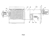
- An exhaust vent 3-5 is disposed on one side of the heat exchange plate 3-2 of the evaporative condenser 3.
- a cooling fan 3-6 is disposed between the heat exchange plate 3-2 and the exhaust vent 3-5.
- a cooling air opening 3-7 is disposed on the other side of the heat exchange plate 3-2. The cooling air opening 3-7 connects with an air pipe 16.
- the air pipe 16 connects through subsidiary pipes 16-1,16-2 with an indoor air outlet 17 and an outdoor air inlet 18.
- the outdoor air inlet 18 is installed with an airflow regulation valve 19 to regulate the mixing ratio of outdoor air and indoor air, and the range of regulation ratio is 0% to 100% (i.e. the mixing ratio of outdoor air to indoor air is 0:1 to 1:1).
- the water cooling system with full heat recovery operates as follows: when the coolant is compressed by the compressor 1 into a high temperature, high pressure gas, it is led by pipes to the heat exchange plate 3-2 of the evaporative condenser 3. When it flows through the heat exchange plate 3-2, the high temperature, high pressure gas is cooled and condensed into a low temperature, high pressure liquid and is lead to the liquid storage member 4 for storage.
- the coolant liquid flows out from the liquid storage member 4 and flows through the drier-filter 5, the liquid mirror 6, the liquid supply electromagnetic valve 7 and the expansion valve 8 to form a low temperature, high pressure gas which enters the tube evaporator 9 and performs heat exchange with the water that flows through the tube evaporator 9, thereby cooling the water.
- the coolant in the form of a low temperature, low pressure gas then flows from the tube evaporator 9 to the compressor 1, which then completes the refrigeration cycle.
- the recycling water pump 3-4 is activated to pump water out from the water tank 3-3 to the water sprayer 3-1.
- the cooling fan 3-6 introduces indoor exhaust air (of lower temperature and relative humidity) and outdoor air from the indoor air outlet 17 and the outdoor air inlet 18 into the evaporative condenser 3 in order to perform heat exchange with the heat exchange plate 3-2 and with the cooling water that flows through the heat exchange plate 3-2.
- the cooling water transfers heat to the cooling air by transferring heat (sensible heat) to the cooling air and by evaporating water (latent heat) of the cooling air.
- the temperature of the cooling water decreases and the temperature of the cooling air (indoor exhaust air and outdoor air) increases. Finally, it is discharged from the machine from the exhaust vent 3-5 through the cooling fan 3-6.
- the condensate pipes 12 in spaces I,II produce a large amount of condensate of relatively low temperature during the process.
- the condensate After the condensate is collected by the water receptacle 14, it converges to the water tank 3-3 through the condensate pipe 15 and mixes with the condensate in the evaporative condenser 3, thereby reducing the overall temperature of the condensate. This serves to assist the cooling of the evaporative condenser 3 and effectively uses the cooling energy and saves water.
Landscapes
- Engineering & Computer Science (AREA)
- Mechanical Engineering (AREA)
- General Engineering & Computer Science (AREA)
- Chemical & Material Sciences (AREA)
- Combustion & Propulsion (AREA)
- Physics & Mathematics (AREA)
- Thermal Sciences (AREA)
- Life Sciences & Earth Sciences (AREA)
- Sustainable Development (AREA)
- Devices For Blowing Cold Air, Devices For Blowing Warm Air, And Means For Preventing Water Condensation In Air Conditioning Units (AREA)
- Other Air-Conditioning Systems (AREA)
Applications Claiming Priority (1)
| Application Number | Priority Date | Filing Date | Title |
|---|---|---|---|
| CNU2004200712084U CN2729570Y (zh) | 2004-07-06 | 2004-07-06 | 全热回收冷水机组 |
Publications (2)
| Publication Number | Publication Date |
|---|---|
| EP1614973A2 true EP1614973A2 (fr) | 2006-01-11 |
| EP1614973A3 EP1614973A3 (fr) | 2006-06-14 |
Family
ID=35048346
Family Applications (1)
| Application Number | Title | Priority Date | Filing Date |
|---|---|---|---|
| EP05014420A Withdrawn EP1614973A3 (fr) | 2004-07-06 | 2005-07-02 | Système de refroidissement par eau avec récupération de chaleur intégral |
Country Status (4)
| Country | Link |
|---|---|
| EP (1) | EP1614973A3 (fr) |
| JP (1) | JP3114447U (fr) |
| CN (1) | CN2729570Y (fr) |
| HK (1) | HK1073972A2 (fr) |
Cited By (15)
| Publication number | Priority date | Publication date | Assignee | Title |
|---|---|---|---|---|
| WO2010006553A1 (fr) * | 2008-07-18 | 2010-01-21 | 广州市华德工业有限公司 | Unité de refroidissement d’eau par condensation et évaporation de type à plaques et tubes munie de matériaux de remplissage |
| CN101865502A (zh) * | 2010-06-13 | 2010-10-20 | 重庆海润节能技术股份有限公司 | 数字化分体式能量回收机组 |
| CN101936584A (zh) * | 2010-09-20 | 2011-01-05 | 西安工程大学 | 夜间辐射冷却与蓄冷技术相结合的蒸发冷却空调系统 |
| US20120024000A1 (en) * | 2010-07-28 | 2012-02-02 | Lg Electronics Inc. | Ice making machine |
| CN104807227A (zh) * | 2015-05-15 | 2015-07-29 | 上海海洋大学 | 一种蒸发式冷凝器实验系统 |
| WO2017144779A1 (fr) | 2016-02-22 | 2017-08-31 | Suomen Ilmastointi Ja Savunpoisto Oy | Agencement écologique pour le perfectionnement du rendement énergétique |
| US9861013B2 (en) | 2015-02-12 | 2018-01-02 | International Business Machines Corporation | Cooling system with integrated fill and drain pump |
| CN108931018A (zh) * | 2018-04-21 | 2018-12-04 | 浙江国祥股份有限公司 | 一种带水力模块的蒸发冷凝一体机 |
| CN110749067A (zh) * | 2019-11-12 | 2020-02-04 | 青岛海信日立空调系统有限公司 | 热回收空调机组及其控制方法及装置 |
| CN111023371A (zh) * | 2019-12-31 | 2020-04-17 | 苏州智允机电系统集成科技有限公司 | 一种水冷空调的水路循环系统 |
| CN112135478A (zh) * | 2020-09-07 | 2020-12-25 | 中铝矿业有限公司 | 一种节能高压变频器降温系统 |
| CN113163689A (zh) * | 2021-04-21 | 2021-07-23 | 西安交通大学 | 一种低功耗自然蒸发冷却服务器机柜 |
| CN113803808A (zh) * | 2021-09-10 | 2021-12-17 | 青岛海信日立空调系统有限公司 | 新风处理装置及空调器 |
| CN114165848A (zh) * | 2021-12-30 | 2022-03-11 | 博乐环境系统(苏州)有限公司 | 多功能新风净化机 |
| CN120702091A (zh) * | 2025-07-24 | 2025-09-26 | 北京凯迪宏业科技有限公司 | 一种暖通空调的余热回收装置 |
Families Citing this family (9)
| Publication number | Priority date | Publication date | Assignee | Title |
|---|---|---|---|---|
| CN100501254C (zh) * | 2007-09-30 | 2009-06-17 | 阿尔西制冷工程技术(北京)有限公司 | 应用自然冷却技术的冷水机组 |
| CN101256043B (zh) * | 2007-12-14 | 2011-05-18 | 华南理工大学 | 板壳式非饱和蒸发冷凝设备 |
| CN102313344A (zh) * | 2010-06-30 | 2012-01-11 | 梅宝军 | 带有换风系统的空调器 |
| CN102759187A (zh) * | 2011-04-26 | 2012-10-31 | 梅宝军 | 换风的汽车空调 |
| CN106515769B (zh) * | 2016-12-05 | 2018-08-21 | 广州精益汽车空调有限公司 | 一种有轨电车车辆空调 |
| CN108507233B (zh) * | 2017-09-19 | 2023-09-29 | 约克广州空调冷冻设备有限公司 | 一种换热系统 |
| CN109297127A (zh) * | 2018-12-03 | 2019-02-01 | 王德明 | 一种具有循环水泵的家用蒸发冷却式空调 |
| CN110542209A (zh) * | 2019-09-16 | 2019-12-06 | 杜嵘 | 一种带热回收功能的小型制冷设备 |
| CN112963905A (zh) * | 2021-03-31 | 2021-06-15 | 上海中建东孚投资发展有限公司 | 用于空调机位的通风散热装置 |
Family Cites Families (5)
| Publication number | Priority date | Publication date | Assignee | Title |
|---|---|---|---|---|
| US4655278A (en) * | 1985-09-27 | 1987-04-07 | Cambridge Manufacturing Climate Control Products Inc. | Heat recirculation apparatus and method |
| CA2155628A1 (fr) * | 1995-08-08 | 1997-02-09 | Yvon Turcotte | Appareil de renouvellement et de conditionnement d'air |
| US5791153A (en) * | 1995-11-09 | 1998-08-11 | La Roche Industries Inc. | High efficiency air conditioning system with humidity control |
| GB2318180A (en) * | 1996-10-08 | 1998-04-15 | Aro Electrical Engineering Co | Air-conditioning apparatus |
| DE29916866U1 (de) * | 1999-09-24 | 2001-02-01 | Ingenieurbüro Timmer Reichel GmbH, 42781 Haan | System zur Energietransformation in Heiz- und Kühlkreisläufen |
-
2004
- 2004-07-06 CN CNU2004200712084U patent/CN2729570Y/zh not_active Expired - Fee Related
-
2005
- 2005-06-30 HK HK05105555A patent/HK1073972A2/xx not_active IP Right Cessation
- 2005-07-02 EP EP05014420A patent/EP1614973A3/fr not_active Withdrawn
- 2005-07-06 JP JP2005005279U patent/JP3114447U/ja not_active Expired - Fee Related
Cited By (23)
| Publication number | Priority date | Publication date | Assignee | Title |
|---|---|---|---|---|
| WO2010006553A1 (fr) * | 2008-07-18 | 2010-01-21 | 广州市华德工业有限公司 | Unité de refroidissement d’eau par condensation et évaporation de type à plaques et tubes munie de matériaux de remplissage |
| CN101865502A (zh) * | 2010-06-13 | 2010-10-20 | 重庆海润节能技术股份有限公司 | 数字化分体式能量回收机组 |
| US20120024000A1 (en) * | 2010-07-28 | 2012-02-02 | Lg Electronics Inc. | Ice making machine |
| EP2413069A3 (fr) * | 2010-07-28 | 2017-08-09 | LG Electronics Inc. | Machine de fabrication de glace |
| CN101936584A (zh) * | 2010-09-20 | 2011-01-05 | 西安工程大学 | 夜间辐射冷却与蓄冷技术相结合的蒸发冷却空调系统 |
| CN101936584B (zh) * | 2010-09-20 | 2013-04-03 | 西安工程大学 | 夜间辐射冷却与蓄冷技术相结合的蒸发冷却空调系统 |
| US9918409B2 (en) | 2015-02-12 | 2018-03-13 | International Business Machines Corporation | Cooling system with integrated fill and drain pump |
| US10660239B2 (en) | 2015-02-12 | 2020-05-19 | International Business Machines Corporation | Cooling system with integrated fill and drain pump |
| US9861013B2 (en) | 2015-02-12 | 2018-01-02 | International Business Machines Corporation | Cooling system with integrated fill and drain pump |
| CN104807227A (zh) * | 2015-05-15 | 2015-07-29 | 上海海洋大学 | 一种蒸发式冷凝器实验系统 |
| EP3420284A4 (fr) * | 2016-02-22 | 2019-10-02 | Suomen Ilmastointi Ja Savunpoisto Oy | Agencement écologique pour le perfectionnement du rendement énergétique |
| WO2017144779A1 (fr) | 2016-02-22 | 2017-08-31 | Suomen Ilmastointi Ja Savunpoisto Oy | Agencement écologique pour le perfectionnement du rendement énergétique |
| CN108931018A (zh) * | 2018-04-21 | 2018-12-04 | 浙江国祥股份有限公司 | 一种带水力模块的蒸发冷凝一体机 |
| CN108931018B (zh) * | 2018-04-21 | 2019-05-14 | 浙江国祥股份有限公司 | 一种带水力模块的蒸发冷凝一体机 |
| CN110749067A (zh) * | 2019-11-12 | 2020-02-04 | 青岛海信日立空调系统有限公司 | 热回收空调机组及其控制方法及装置 |
| CN111023371A (zh) * | 2019-12-31 | 2020-04-17 | 苏州智允机电系统集成科技有限公司 | 一种水冷空调的水路循环系统 |
| CN112135478A (zh) * | 2020-09-07 | 2020-12-25 | 中铝矿业有限公司 | 一种节能高压变频器降温系统 |
| CN113163689A (zh) * | 2021-04-21 | 2021-07-23 | 西安交通大学 | 一种低功耗自然蒸发冷却服务器机柜 |
| CN113163689B (zh) * | 2021-04-21 | 2022-07-12 | 西安交通大学 | 一种低功耗自然蒸发冷却服务器机柜 |
| CN113803808A (zh) * | 2021-09-10 | 2021-12-17 | 青岛海信日立空调系统有限公司 | 新风处理装置及空调器 |
| CN113803808B (zh) * | 2021-09-10 | 2022-11-29 | 青岛海信日立空调系统有限公司 | 新风处理装置及空调器 |
| CN114165848A (zh) * | 2021-12-30 | 2022-03-11 | 博乐环境系统(苏州)有限公司 | 多功能新风净化机 |
| CN120702091A (zh) * | 2025-07-24 | 2025-09-26 | 北京凯迪宏业科技有限公司 | 一种暖通空调的余热回收装置 |
Also Published As
| Publication number | Publication date |
|---|---|
| EP1614973A3 (fr) | 2006-06-14 |
| HK1073972A2 (en) | 2005-10-21 |
| JP3114447U (ja) | 2005-10-27 |
| CN2729570Y (zh) | 2005-09-28 |
Similar Documents
| Publication | Publication Date | Title |
|---|---|---|
| US7370490B2 (en) | Air-conditioning system with full heat recovery | |
| EP1614973A2 (fr) | Système de refroidissement par eau avec récupération de chaleur intégral | |
| EP1617153A2 (fr) | Système de conditionnement d'air avec récupération de chaleur intégrale | |
| US7266970B2 (en) | Water cooling system with full heat recovery | |
| CN201163076Y (zh) | 风冷制冷设备节能器 | |
| CN207584985U (zh) | 新风集成节能空调 | |
| CN207584984U (zh) | 一种复合式节能空调 | |
| CN205065912U (zh) | 适用于数据中心的热管-热回收型蒸发冷却空调系统 | |
| CN211792609U (zh) | 一种数据中心用间接蒸发冷却空调机组 | |
| CN105135572A (zh) | 数据中心用热管复合热回收型蒸发冷却空调系统 | |
| CN211854313U (zh) | 一种间接蒸发冷却系统 | |
| CN209386464U (zh) | 一种间接蒸发冷却机组 | |
| CN114427718A (zh) | 一种双冷源间接蒸发冷机组 | |
| CN207247488U (zh) | 模块组合式间接换热芯体 | |
| CN217635978U (zh) | 一种节水闭式热源塔 | |
| CN2199467Y (zh) | 水蒸发制冷间壁式节能空调机 | |
| CN101793427B (zh) | 可连续喷雾的风冷雾化蒸发式冷凝系统及空气调节方法 | |
| CN104534584B (zh) | 地铁大小环境用蒸发冷却与蒸发冷凝相结合的空调系统 | |
| CN211400852U (zh) | 一种大型消雾节水复合型闭式冷却塔 | |
| CN107894044A (zh) | 适用于西北地区数据中心的自然冷却空调机组 | |
| CN209840328U (zh) | 一种数据中心机房双冷蒸发冷却-冷凝一体化空调机组 | |
| CN217031428U (zh) | 一种双冷源间接蒸发冷机组 | |
| CN201662164U (zh) | 可连续喷雾的风冷雾化蒸发式冷凝系统 | |
| CN105091169B (zh) | 一种应用于数据中心的冷却系统及控制方法 | |
| CN2553290Y (zh) | 间接蒸发制冷式新风机组 |
Legal Events
| Date | Code | Title | Description |
|---|---|---|---|
| PUAI | Public reference made under article 153(3) epc to a published international application that has entered the european phase |
Free format text: ORIGINAL CODE: 0009012 |
|
| AK | Designated contracting states |
Kind code of ref document: A2 Designated state(s): AT BE BG CH CY CZ DE DK EE ES FI FR GB GR HU IE IS IT LI LT LU LV MC NL PL PT RO SE SI SK TR |
|
| AX | Request for extension of the european patent |
Extension state: AL BA HR MK YU |
|
| PUAL | Search report despatched |
Free format text: ORIGINAL CODE: 0009013 |
|
| AK | Designated contracting states |
Kind code of ref document: A3 Designated state(s): AT BE BG CH CY CZ DE DK EE ES FI FR GB GR HU IE IS IT LI LT LU LV MC NL PL PT RO SE SI SK TR |
|
| AX | Request for extension of the european patent |
Extension state: AL BA HR MK YU |
|
| 17P | Request for examination filed |
Effective date: 20061214 |
|
| 17Q | First examination report despatched |
Effective date: 20070111 |
|
| AKX | Designation fees paid |
Designated state(s): DE ES FR GB IT NL |
|
| STAA | Information on the status of an ep patent application or granted ep patent |
Free format text: STATUS: THE APPLICATION HAS BEEN WITHDRAWN |
|
| 18W | Application withdrawn |
Effective date: 20080920 |