EP1614996B1 - Procédé et système de planification dynamique d'itinéraire - Google Patents
Procédé et système de planification dynamique d'itinéraire Download PDFInfo
- Publication number
- EP1614996B1 EP1614996B1 EP05104941A EP05104941A EP1614996B1 EP 1614996 B1 EP1614996 B1 EP 1614996B1 EP 05104941 A EP05104941 A EP 05104941A EP 05104941 A EP05104941 A EP 05104941A EP 1614996 B1 EP1614996 B1 EP 1614996B1
- Authority
- EP
- European Patent Office
- Prior art keywords
- time
- edge
- route planning
- route
- travel time
- Prior art date
- Legal status (The legal status is an assumption and is not a legal conclusion. Google has not performed a legal analysis and makes no representation as to the accuracy of the status listed.)
- Expired - Lifetime
Links
Images



Classifications
-
- G—PHYSICS
- G08—SIGNALLING
- G08G—TRAFFIC CONTROL SYSTEMS
- G08G1/00—Traffic control systems for road vehicles
- G08G1/09—Arrangements for giving variable traffic instructions
- G08G1/0962—Arrangements for giving variable traffic instructions having an indicator mounted inside the vehicle, e.g. giving voice messages
- G08G1/0968—Systems involving transmission of navigation instructions to the vehicle
- G08G1/096833—Systems involving transmission of navigation instructions to the vehicle where different aspects are considered when computing the route
- G08G1/096844—Systems involving transmission of navigation instructions to the vehicle where different aspects are considered when computing the route where the complete route is dynamically recomputed based on new data
-
- G—PHYSICS
- G01—MEASURING; TESTING
- G01C—MEASURING DISTANCES, LEVELS OR BEARINGS; SURVEYING; NAVIGATION; GYROSCOPIC INSTRUMENTS; PHOTOGRAMMETRY OR VIDEOGRAMMETRY
- G01C21/00—Navigation; Navigational instruments not provided for in groups G01C1/00 - G01C19/00
- G01C21/26—Navigation; Navigational instruments not provided for in groups G01C1/00 - G01C19/00 specially adapted for navigation in a road network
- G01C21/34—Route searching; Route guidance
- G01C21/3453—Special cost functions, i.e. other than distance or default speed limit of road segments
-
- G—PHYSICS
- G01—MEASURING; TESTING
- G01C—MEASURING DISTANCES, LEVELS OR BEARINGS; SURVEYING; NAVIGATION; GYROSCOPIC INSTRUMENTS; PHOTOGRAMMETRY OR VIDEOGRAMMETRY
- G01C21/00—Navigation; Navigational instruments not provided for in groups G01C1/00 - G01C19/00
- G01C21/26—Navigation; Navigational instruments not provided for in groups G01C1/00 - G01C19/00 specially adapted for navigation in a road network
- G01C21/34—Route searching; Route guidance
- G01C21/3453—Special cost functions, i.e. other than distance or default speed limit of road segments
- G01C21/3484—Personalized, e.g. from learned user behaviour or user-defined profiles
-
- G—PHYSICS
- G01—MEASURING; TESTING
- G01C—MEASURING DISTANCES, LEVELS OR BEARINGS; SURVEYING; NAVIGATION; GYROSCOPIC INSTRUMENTS; PHOTOGRAMMETRY OR VIDEOGRAMMETRY
- G01C21/00—Navigation; Navigational instruments not provided for in groups G01C1/00 - G01C19/00
- G01C21/26—Navigation; Navigational instruments not provided for in groups G01C1/00 - G01C19/00 specially adapted for navigation in a road network
- G01C21/34—Route searching; Route guidance
- G01C21/3453—Special cost functions, i.e. other than distance or default speed limit of road segments
- G01C21/3492—Special cost functions, i.e. other than distance or default speed limit of road segments employing speed data or traffic data, e.g. real-time or historical
Definitions
- the invention relates to a method for dynamic route planning in a route planning system in which a route between a starting point and a destination point is calculated within a road network divided into individual edges and nodes, the route being determined as a function of edge properties associated with the edges , Furthermore, the invention relates to a route planning system for dynamic route planning with a computing unit, which is connected to an input unit, a display unit and a first memory, which contains a divided into individual edges and nodes road network, the computing unit for calculating a route within the road network between a starting point and a destination point, in dependence on the edge properties assigned to the edges.
- Route planning systems with static route planning are known, in particular, from navigation devices permanently installed in motor vehicles.
- handheld portable devices such as PDAs or mobile radio devices extended by a position detection module are also able to carry out static route planning and subsequent navigation of a user along this route.
- pure route planning systems with which only a static route planned, but no navigation can be performed.
- Static route planning refers to the determination of a route in a road network between a start and a destination point, where the road network is static, ie, fixed in time.
- the road network stored in a memory of the route planning system is subdivided into edges and nodes, wherein the edges are each assigned their own edge properties, which are understood as route planning costs.
- the route planning algorithm now searches for the route between the start and the destination point, which optimizes or minimizes a certain cost criterion.
- cost criteria can be, for example, the length of the entire route, driving on as few freeways as possible, the fastest possible reaching of the destination point, etc.
- the edge properties are correspondingly assigned to the length of the edge, the average speed for this edge or the road type of the edge.
- a known extension of the conventional functionality is the dynamic route planning taking into account current traffic information.
- the traffic information received by radio is evaluated with regard to its relevance to the previously statically planned route. If, as a result of a traffic obstruction, the travel time required to cover the static route increases, a dynamic route is planned and either offered to the user for selection or as a new route for subsequent navigation.
- dynamic route planning the edge properties associated with the road network edges concerned are changed in accordance with the traffic information, ie, for example, the average speed is reduced. This increases accordingly the route planning costs for this edge.
- dynamic route planning it holds that after calculating a first, namely the static, Route in case of changes of edge properties a second route is calculated.
- the travel time extension generally has to be determined by the route planning system, which is only possible by a rough estimate, since a traffic jam length is still nothing says about a mean speed in this jam.
- the beats DE-10219500-A1 to indicate to the user the clogging length and to let him estimate the travel time extension based on his experience. In traffic areas unknown to the user, however, this will not be so easily possible.
- this embodiment requires interaction between the user and the route planning system while driving, which may be distracting or distracting.
- Another disadvantage of the dynamic route planning based on information transmitted by traffic information is that the information has only binary content, ie "jam present / not available". This results in a sudden change in the travel time predicted by the route planning.
- a method and a device for providing traffic information for a vehicle on a traffic route network are known. Based on a start location and start time, current and predicted traffic data are determined in a traffic center and processed to be transferable to the vehicle. In the center based on existing traffic data depending on the starting location and start time by means of a traffic-dependent route search method optimized for the cost function route calculated each line edge.
- the existing traffic data comprises at least the current predicted functional values of a traffic-dependent cost function for the individual route edges.
- the associated time of arrival is determined and the cost function value associated with the determining time of arrival is selected.
- the cost function values selected in this way are then optionally processed with further traffic data as transferable traffic information.
- a device in a vehicle time-determines the position of the vehicle within a digital road map using information provided by a position determination system.
- the time-related vehicle positions are transmitted to a traffic service center.
- the traffic service center collects data from all vehicles equipped with such devices that travel on a road network in a predetermined area.
- the traffic service center processes the data and provides real-time traffic information.
- the device in the vehicle receives the digital road map and the real-time traffic information and determines a route for a driver using the device.
- the traffic information is based on predictions of normal traffic situations derived from archived data and adjusted by factors adapted to the real-time traffic situation.
- Object of the present invention is to provide a method and a route planning system of the type mentioned, which solve the problems of dynamic route planning mentioned.
- At least one edge of the road network is assigned an estimated driving time as the edge property, the estimated driving time being dependent on a predetermined point in time.
- time-dependent travel time allows a time-dependent route planning.
- a time-dependent route planning is in turn nothing more than a dynamic route planning, since in this case the time-varying traffic conditions within the road network are taken into account.
- the fact is known, for example, in the course of a day, the traffic load of certain sections is subject to significant fluctuations. Depending on when a user passes certain sections of the route, he needs a shorter or longer travel time.
- the route planning for routes along this at least one edge can predict different total travel times required, for example, depending on the time of day or time.
- the total travel times result from the sum of the time or the time-dependent travel times and the static travel time for the other edges of the route, the static travel time with the usual methods, so for example from the sum of the edge lengths and the average speed is determined .
- the previously rough estimate of travel time changes due to traffic information is replaced by accurate data. An additional interaction with the user is no longer required and the predicted driving time changes gradually with the given time and no longer in large jumps. A gradual construction and dismantling of traffic jams is therefore taken directly into account.
- the estimated travel time for the at least one edge is provided with a reliability value.
- This reliability value also represents an edge property and allows an evaluation of the total travel time calculated by the route planning. The higher this value is, the more the user can be sure that his required travel time for the affected edge will not exceed the anticipated travel time.
- the more edges of the route are provided with a time-dependent driving time and such a reliability value, the more reliable is the value of the predicted total time.
- the reliability value is obtained according to a particular embodiment from a historical time profile of the standard deviation of the actual travel time or the standard deviation of the average speed of the at least one edge.
- the actual travel time or the average speed is recorded not only over a certain period of time but over several equal time periods, for example several successive montages. This results in several comparable time profiles of the respective size whose standard deviation can be calculated.
- a high standard deviation means a low value of reliability, i.
- an associated reliability value could be obtained from the inverse of the standard deviation.
- the probable travel time which is dependent on a predefined time, is stored in the first or in a second memory at the at least one edge of the road network.
- this information is contained in the read-only memory or a memory of the route planning system.
- the at least one edge is preferably an edge affected by cyclical traffic obstructions.
- an edge is chosen which is subject to particularly strong fluctuations in the anticipated travel time, since such an edge has the greatest influence on the travel time required for the entire route, referred to below as the total travel time.
- the predetermined time, on which the estimated travel time depends is preferably the time of day and / or the day of the week. It may be useful for space reasons, depending on whether the traffic delays distributed only over the day, distributed only over a week or fluctuate sharply on each day of the week, according to only the time of day, only the day of the week or both sizes of vorausfahrliclien travel time , Furthermore, for regions where there are strong seasonal differences, such as tourism areas, the month as a date is also conceivable.
- the predetermined time is determined as the time at which the user of the route planning system is likely to reach the at least one edge. Either the user specifies this time directly or is calculated by the route planning system based on the time of departure and the place of departure of the user. In this way, therefore, a departure-time-dependent route planning can be performed, with the help of which a user can clarify, for example, in advance, at what time of day the expected fastest Ride is possible. For business travelers, for example, this offers the possibility to adjust the appointments of one day to the anticipated traffic situation in order to spend as little time as possible in the vehicle and as much as possible with the customers.
- the navigation system belonging to a navigation system can start from the currently measured time and the current location of the user at the presumable time of reaching the at least one edge shut down.
- the probable travel time for the at least one edge is obtained from a historical time profile of the average speed of this edge and in another embodiment from the historical time profile of the actual travel time of this edge.
- Such time profiles are obtained by simple measurements by recording the respective variable over a certain period of time, for example the course of a day, a week or a month. With such a time profile, therefore, a direct, for example tabular, association between a fixed point in time and the measured size is possible. From the assigned actual travel time or the average speed and the edge length can then be determined in a simple manner, the estimated travel time at the respective time.
- a further, representing the route planning costs for this edge to the at least one edge, Size generated. This depends on the route planning algorithm used and the cost criterion to be optimized. If, for example, a route is sought whose total average speed is to reach the highest possible value, then the time-dependent driving time can be converted into a time-dependent average speed using the edge length. Another example is a normalized to a dimensionless size costs, in the calculation of the time-dependent driving time is included.
- the user can specify a desired degree of reliability of the total travel time, which is taken into account during the route planning.
- the time-dependent estimated driving times obtained by measurements or statistical investigations, although the traffic situation for the at least one edge on average very well, but can scatter in their individual values arbitrarily far.
- the user can be given a sense of the reliability of the predicted total travel time. If it is particularly important to him that the predicted total travel time is not exceeded, he chooses a high desired degree of reliability.
- a first cost criterion to be optimized by the route planning is adapted to the desired degree of reliability.
- a cost criterion also used in static route planning algorithms is used, namely the minimization of the sum of the estimated travel times of all edges forming a route.
- the estimated travel times are either time-dependent or static travel times.
- the adaptation of this first cost criterion to the desired degree of reliability preferably takes place by increasing the route planning costs as a function of the reliability value assigned to the at least one edge.
- the edge-related, time-dependent anticipated travel time is increased by an amount of uncertainty which decreases with increasing reliability value.
- the uncertainty amount must increase with increasing standard deviation accordingly.
- a second cost criterion to be optimized is introduced in addition to the first, and the first and the second cost criterion are weighted differently depending on the desired degree of reliability.
- the weighted cost criteria are then summarized to a higher cost value, so that the route planning is searched for a route that optimizes the parent cost.
- the first cost criterion which is also used for static route planning, is maintained unchanged in this embodiment and the second cost criterion additionally takes into account the desired degree of reliability. If the user does not specify a desired degree, then the second cost criterion is simply weighted zero and the route planning algorithm runs in a conventional manner.
- the sum of the reliability values of all edges forming a route is minimized in a particular embodiment.
- a weighting of the first and second cost criterion is preferably carried out so that with increasing the desired degree of reliability, the first cost criterion is weighted lower and the second cost criterion higher. In relation to the particular embodiment, this means that with higher desired reliability, the sum of the reliability values of all edges is more strongly included in the superordinate cost value, and the sum of the travel times of all edges less pronounced. In this way, a compromise is found between the desire for the lowest overall travel time and the desire for the highest possible reliability, since the route with the highest reliability may be one of the slowest routes.
- the input unit of the route planning system is designed so that the user can specify or select the desired degree of reliability of the total travel time.
- a direct input or input could be made by keyboard or speech recognition and a selection by scroll or cursor function in conjunction with an enter function.
- a module for determining the current time is connected to the arithmetic unit.
- the route planning system can either the departure time of the user or, in the case that the user is already on the route, determine the current time associated with a current location. In both cases, the computing unit of the route planning system is then able to determine the point in time at which the user is expected to reach the at least one edge.
- a module for receiving traffic information is present.
- the traffic information is not always included in the route planning, but only after exceeding a predetermined severity level of the traffic obstruction.
- the threshold of severity for example, may be defined as a minimum travel time extension. Since, according to the invention, cyclical recurring traffic obstructions and the associated travel time extension are already taken into account, only extraordinary events, such as full closures, construction sites or particularly long traffic jams, are passed on to the route planning. These extraordinary events are then considered in the known manner as traffic information in the dynamic route planning.
- FIG. 1 the components of a built in a motor vehicle route planning system are shown, wherein the route planning system is designed for a time-dependent route planning.
- This route planning system is integrated in an unillustrated navigation system for the subsequent navigation of the driver along the calculated route.
- the central element of the route planning system is the arithmetic unit 1, to which all other components are connected, namely an input unit 2, a display unit 3, a database stored in a first, non-volatile memory 5, a second volatile memory 4, position-determining means 6, a module for setting up a wireless communication link 7, a module for determining the current time 8 and a module for receiving traffic information 9.
- the modules for setting up a wireless communication link 7, for determining the current time 8 and for receiving traffic information 9 are optional because the information obtained about it could also be obtained by other means, for example by user input.
- the superior navigation system has in addition to the elements belonging to the route planning system further means for more accurate determination of the current position, such as a yaw rate sensor and interfaces to Radcardsensoren. Insofar as a more exact positional determination than the pure GPS position measurement by means of module 6 is not possible, the pure GPS information is sufficient for the purposes of dynamic route planning, since an approximate knowledge is required for planning a new, dynamic route depending on the current location of the user this location is sufficient.
- the first memory 5 of the route planning system contains a road network which is divided into nodes L i and edges M j , wherein each M j is assigned an anticipated travel time F j .
- each M j is assigned an anticipated travel time F j .
- the edges M j are assigned the travel time F j in the form of a historical time profile of the mean velocity or the actual travel time F jT of these edges, these edges M j either to the group of streets with the highest category, ie highways and expressways, or belonging to the group of main and through roads in agglomerations.
- the storage of the historical time profiles for all edges M j is also conceivable.
- the arithmetic unit 1 can perform a dynamic, time-dependent route planning.
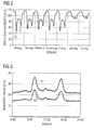
- FIG. 2 shows a historical time profile of the average speed, which was determined in the course of a week on a section of a freeway near Antwerp by measurements. One sees the clear differences during the course of a day and in comparison between the working days and the days at the weekend.
- the average speed has two significant drops in speed every week, such as on Monday the speed drops 10 and 11, at times of rush hour occur in the morning (10) and in the afternoon (11).
- the arithmetic unit 1 would convert the read for a given time, for example Monday, 10:24 clock, read from the memory 5 average speed of about 80 km / h in a probable travel time by the length of the to Section near Antwerp belonging edge M j divided by the velocity value.
- This conversion step is reflected in the route planning system FIG. 1 but still saved because instead of the average speed, the actual travel time F jT is stored as a historical time profile .
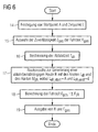
- Two profiles 12 and 13 of a measured driving time are in FIG. 3 where both profiles were taken for the same edge M j , only on different but comparable days, such as two consecutive Tuesdays. You can see the value of the measured travel time in minutes over the course of a day between 0:00 and 24:00.
- the driving time on the two days shows qualitatively a similar profile with the expected travel time extensions at the times of commuter traffic, but deviates on average from each other.
- the profile 12 shows a driving time that is about 10 minutes longer.
- the route planning procedure carried out on this basis is determined by the schedules of the FIGS. 6 and 7 clarified.
- the starting point A and the destination point E of the route are determined in step 14.
- the starting point A can determine the route planning system by a GPS measurement by means 6 for position determination. However, it can also be specified differently by the user by means of the input unit 2.
- the destination E is specified by the user. Furthermore, in step 15, the user selects, for example, three possible levels-high, medium, low-the desired degree of reliability Z tot of the total travel time F tot .
- step 16 the module 8 determines from the current time and the current day as departure time T. It is also conceivable that the user specifies a deviating departure time T ab , for example, for a trip in the future.
- the central method step of route planning namely the route search performed by the arithmetic unit 1 in step 17 to generate a departure-time-dependent route R, is based on FIG. 7 explained in more detail.
- the total travel time F ges calculated in step 18 from the sum of the travel times F jR of the edges M jR contained in the route R and the route R itself are output on the display unit 3 in step 19.
- the route search for FIG. 7 has the result of a departure-time-dependent route R with the nodes L iR and the edges M jR , the start node L iR, start corresponds to the starting point A and the end node L iR, end the destination point E (see FIG. FIG. 6 ).
- the route search runs as a loop, starting at the start node L iR, start (step 20). The loop continues until the node L i to be examined next corresponds to the destination point E (step 21) and so that the end of the route R is reached. From the departure time T ab and the traveled between the start node L iR, start and the node to be examined L i , previous travel time is in step 22 by summation the arrival time T an, i calculated at the node L i . The outgoing from the node to be examined L i edges M j are determined in step 23 and examined which of these edges M j contributes with its cost criterion K j least to the cost criterion K ges of the route R.
- step 24 from the historical time profiles stored in the first memory 5, the values of the actual travel time F jT and the standard deviation S j associated with the time T an, i are retrieved , the actual travel time F jT being considered as the expected travel time F j .
- the F j and S j belonging to the time T an, i, or also the sections of the historical time profiles which belong to a time including T , i can be received by an external server via the GSM module 7 via an external remote server and stored directly in the working memory, so the second memory 4, the route planning system.
- storage space in the first memory 5 can be saved since the historical time profiles are all stored in an external memory.
- the external server can, for example, be located in a traffic control center from which the time profiles measured by FCD vehicles (floating car data) or stationary sensors on the routes are evaluated, stored in the external memory as historical time profiles, and on request the route planning system are transmitted.
- the cost K j is then calculated in step 25 by increasing the expected travel time F j of each edge M j by the product of standard deviation S j and the desired degree of reliability Z ges .
- the edges M j with the broader dispersion of measured travel times thus receive higher costs K j and are therefore less likely to enter route R.
- the weighting of the standard deviation S j with the desired reliability Z ges increases the influence of a wider spread even more, so that the edges M j with the least reliability are the least represented in the route R. which increases the certainty that the travel time required by the user for the route R does not exceed the value of the total time F ges predicted by the route planning.
- the edge M jR for which the sum of the costs K j is minimal, is searched for in step 26 from the edges M j departing from the node L i , the sum being over all the edges previously assigned to the route R and via each one of L i outgoing edges M j is running. At this point, it is also sufficient to find the edge M jR with the least own cost component K jR , since only for this edge also the sum over all previous edges becomes minimal. The found edge M jR is added to the previously found route R.
- this node represents the starting node of M jR .
- the node located at the other end of the edge M jR thus forms the end node, starting the route search from this end node (step 27).
- the FIG. 5 shows the result for two route planning between a starting point A and a destination point E with different desired degree of reliability Z tot .
- the route 29 has been found ges for a low degree of reliability Z and the route 28 for a higher degree.
- Route 28 tends to have lesser-category roads than rural and secondary roads, while Route 29 has highways. This is due to the fact that in this area of the route network, the highways have larger standard deviations and thus a wider dispersion of the estimated travel times than the sibling roads.
Landscapes
- Engineering & Computer Science (AREA)
- Radar, Positioning & Navigation (AREA)
- Remote Sensing (AREA)
- Physics & Mathematics (AREA)
- Automation & Control Theory (AREA)
- General Physics & Mathematics (AREA)
- Health & Medical Sciences (AREA)
- General Health & Medical Sciences (AREA)
- Social Psychology (AREA)
- Mathematical Physics (AREA)
- Navigation (AREA)
- Traffic Control Systems (AREA)
Claims (23)
- Procédé permettant la planification dynamique d'itinéraires dans un système de planification d'itinéraires, dans lequel procédé- un itinéraire (R) est calculé, entre un point de départ (A) et un point de destination (E), à l'intérieur d'un réseau de routes divisé en différentes arêtes ou sections (Mj) et sommets (Li), l'itinéraire (R) étant déterminé en fonction de propriétés des arêtes ou sections affectées aux arêtes ou sections (Mj),- un temps de parcours probable (Fj) est affecté en tant que propriété de l'arête ou section à au moins une arête ou section (Mj), le temps de parcours probable (Fj) dépendant d'un moment donné,caractérisé par le fait que le temps de parcours probable (Fj) est doté d'un facteur de fiabilité pour la au moins une arête ou section (Mj).
- Procédé selon la revendication 1, caractérisé par le fait que le facteur de fiabilité pour la au moins une arête ou section (Mj) est obtenu à partir d'un profil historique dans le temps de la variation standard (Sj) du temps de parcours effectif (FjT) ou de la vitesse moyenne sur cette arête ou section (Mj).
- Procédé selon l'une des revendications précédentes, caractérisé par le fait que la au moins une arête ou section (Mj) est une arête ou section touchée par des entraves cycliques à la circulation.
- Procédé selon l'une des revendications précédentes, caractérisé par le fait que le moment donné est un moment de la journée et/ou un jour de la semaine.
- Procédé selon l'une des revendications précédentes, caractérisé par le fait que le moment donné est déterminé comme étant le moment (Tan,i) auquel un utilisateur du système de planification d'itinéraires parvient probablement à la au moins une arête ou section (Mj).
- Procédé selon la revendication 5, caractérisé par le fait que le moment donné est déterminé en partant du temps réel actuel et du lieu de séjour actuel de l'utilisateur du système de planification d'itinéraires.
- Procédé selon l'une des revendications précédentes, caractérisé par le fait que le temps de parcours probable (Fj) pour la au moins une arête ou section est obtenu à partir d'un profil historique dans le temps de la vitesse moyenne sur cette arête ou section.
- Procédé selon l'une des revendications précédentes, caractérisé par le fait que le temps de parcours probable (Fj) pour la au moins une arête ou section est obtenu à partir d'un profil historique dans le temps de la durée effective de parcours (FjT) sur cette arête ou section.
- Procédé selon l'une des revendications précédentes, caractérisé par le fait que le temps de parcours probable (Fj) pour la au moins une arête ou section (Mj) est converti en une grandeur représentant le coût (Kj) de la planification d'itinéraires pour cette arête ou section (Mj).
- Procédé selon l'une des revendications précédentes, caractérisé par le fait qu'il est tenu compte, pour la planification d'itinéraires, d'un degré de fiabilité (Zges), souhaité et prescrit par l'utilisateur, du temps de parcours (Fges) sur l'ensemble de l'itinéraire (R).
- Procédé selon la revendication 10, caractérisé par le fait qu'un premier critère de coûts à optimiser par la planification d'itinéraires est adapté au degré de fiabilité (Zges) souhaité.
- Procédé selon la revendication 11, caractérisé par le fait que le premier critère de coûts est la minimisation de la somme des temps de parcours probables (FjR) sur toutes les arêtes ou sections (MjR) formant un itinéraire (R).
- Procédé selon la revendication 12, caractérisé par le fait que les coûts (Kj) de la planification d'itinéraires pour la au moins une arête ou section (Mj) découlent de l'augmentation du temps de parcours probable (Fj) d'une valeur d'incertitude qui diminue au fur et à mesure que le facteur de fiabilité augmente.
- Procédé selon la revendication 11, caractérisé par le fait qu'il faut que la planification d'itinéraires optimise un deuxième critère de coûts et que le premier et le deuxième critère de coûts sont pondérés différemment en fonction du degré souhaité de fiabilité (Zges), puis sont assemblés pour former un facteur de coûts d'ordre supérieur.
- Procédé selon la revendication 14, caractérisé par le fait que le deuxième critère de coûts est la minimisation de la somme des facteurs de fiabilité (Sj) de toutes les arêtes ou sections (Mj) formant un itinéraire.
- Procédé selon l'une des revendications précédentes 14 ou 15, caractérisé par le fait que, en fonction de l'augmentation du degré de fiabilité (Zges), le premier critère de coûts est pondéré plus faiblement et le deuxième critère de coûts est pondéré plus fortement.
- Système de planification d'itinéraires destiné à une planification dynamique d'itinéraires, comportant une unité de calcul (1), laquelle est reliée à une unité de saisie (2), une unité d'affichage (3) et une première mémoire (5), laquelle stocke un réseau de routes divisé en différentes arêtes ou sections (Mj) et sommets (Li), où l'unité de calcul (1) est configurée pour le calcul d'un itinéraire (R) entre un point de départ (A) et un point de destination (E) à l'intérieur d'un réseau de routes, en fonction de propriétés des arêtes ou sections affectées aux arêtes ou sections (Mj) et où un temps de parcours probable (Fj) dépendant d'un moment donné est stocké dans la première (5) ou dans une deuxième mémoire (4) pour au moins l'une des arêtes ou sections (Mj) du réseau de routes, caractérisé par le fait que le temps de parcours probable (Fj) pour la au moins une arête ou section (Mj) est doté d'un facteur de fiabilité et qu'un utilisateur peut, à l'aide de l'unité de saisie (2), prescrire ou sélectionner un degré souhaité de fiabilité (Zges) du temps de parcours (Fges) sur l'ensemble de l'itinéraire (R).
- Système de planification d'itinéraires selon la revendication 17, caractérisé par le fait qu'un profil historique dans le temps de la vitesse moyenne sur la au moins une arête ou section (Mj) est stocké dans la première (5) ou dans la deuxième mémoire (4).
- Système de planification d'itinéraires selon l'une des revendications précédentes 17 ou 18, caractérisé par le fait qu'un profil historique dans le temps de la durée effective de parcours (FjT) de la au moins une arête ou section (Mj) est stocké dans la première (5) ou dans la deuxième mémoire (4).
- Système de planification d'itinéraires selon l'une des revendications précédentes 17 à 19, caractérisé par le fait qu'un module (8) destiné à la détermination du temps réel actuel est relié à l'unité de calcul (1).
- Système de planification d'itinéraires selon l'une des revendications précédentes 17 à 19, caractérisé par le fait qu'un moyen (6) destiné à la détermination de la position est relié à l'unité de calcul (1).
- Système de planification d'itinéraires selon l'une des revendications précédentes 17 à 20, caractérisé par le fait qu'un profil historique dans le temps de la variation standard (Sj) de la durée effective de parcours (FjT) de la au moins une arête ou section (Mj) est stocké dans la première (5) ou dans la deuxième mémoire (4).
- Système de planification d'itinéraires selon l'une des revendications précédentes 17 à 21, caractérisé par le fait qu'un module (9) permettant de recevoir des informations relatives au trafic routier est relié à l'unité de calcul (1) et que les informations relatives au trafic routier ne sont prises en compte dans la planification d'itinéraires que lorsque la gravité des entraves à la circulation dépasse une valeur donnée.
Applications Claiming Priority (1)
| Application Number | Priority Date | Filing Date | Title |
|---|---|---|---|
| DE102004032495A DE102004032495A1 (de) | 2004-07-05 | 2004-07-05 | Verfahren und Routenplanungssystem zur dynamischen Routenplanung |
Publications (2)
| Publication Number | Publication Date |
|---|---|
| EP1614996A1 EP1614996A1 (fr) | 2006-01-11 |
| EP1614996B1 true EP1614996B1 (fr) | 2008-12-24 |
Family
ID=34981714
Family Applications (1)
| Application Number | Title | Priority Date | Filing Date |
|---|---|---|---|
| EP05104941A Expired - Lifetime EP1614996B1 (fr) | 2004-07-05 | 2005-06-07 | Procédé et système de planification dynamique d'itinéraire |
Country Status (2)
| Country | Link |
|---|---|
| EP (1) | EP1614996B1 (fr) |
| DE (2) | DE102004032495A1 (fr) |
Families Citing this family (12)
| Publication number | Priority date | Publication date | Assignee | Title |
|---|---|---|---|---|
| DE102005033753A1 (de) * | 2005-07-15 | 2007-01-18 | Ptv Ag | Verfahren zum Berechnen einer geeigneten Strecke und Navigationssystem |
| JP4801481B2 (ja) * | 2006-03-30 | 2011-10-26 | クラリオン株式会社 | ナビゲーション装置、ナビゲーションシステム |
| DE102007026493A1 (de) * | 2007-06-05 | 2008-12-11 | Deutsche Telekom Ag | Verfahren zur dynamischen Navigation von Individualverkehr sowie Vorrichtung, Einrichtung und System dafür |
| WO2009036844A1 (fr) * | 2007-09-21 | 2009-03-26 | Tomtom International B.V. | Appareil de navigation et procédé pour celui-ci |
| DE102007058092A1 (de) * | 2007-12-03 | 2009-06-04 | Robert Bosch Gmbh | Verfahren zum Betrieb eines Informationssystems und ein Informationssystem |
| DE102007060590A1 (de) * | 2007-12-13 | 2009-06-18 | Deutsche Telekom Ag | Verfahren zur Auswahl einer Route für eine dynamische Navigation von Individualverkehr |
| GB201211614D0 (en) * | 2012-06-29 | 2012-08-15 | Tomtom Dev Germany Gmbh | Generating alternative routes |
| JP6298322B2 (ja) * | 2014-02-27 | 2018-03-20 | 株式会社ゼンリン | 経路探索装置、経路探索方法およびプログラム |
| DE112014006929B4 (de) | 2014-09-05 | 2023-03-02 | Mitsubishi Electric Corporation | Autonomes Fahrmanagementsystem, Server und autonomes Fahrmanagementverfahren |
| DE102015208806A1 (de) * | 2015-05-12 | 2016-11-17 | Bayerische Motoren Werke Aktiengesellschaft | Optimierte Fahrtroutenempfehlung durch Navigationssystem |
| CN111796516B (zh) * | 2019-04-03 | 2024-07-19 | 北京京东乾石科技有限公司 | 用于规划轨迹的方法和装置 |
| CN110428101B (zh) * | 2019-07-31 | 2023-04-18 | 重庆长安汽车股份有限公司 | 基于历史出行规律的目的地预测方法及计算机可读存储介质 |
Family Cites Families (9)
| Publication number | Priority date | Publication date | Assignee | Title |
|---|---|---|---|---|
| US5933100A (en) * | 1995-12-27 | 1999-08-03 | Mitsubishi Electric Information Technology Center America, Inc. | Automobile navigation system with dynamic traffic data |
| DE19810126A1 (de) * | 1998-03-09 | 1999-09-16 | Techno Trend Systemtechnik Gmb | Verfahren zur rechnergestützten Routenfindung für Fahrzeugführer |
| DE19858477B4 (de) * | 1998-12-17 | 2004-12-02 | Siemens Ag | Verfahren zum Ermitteln von Verkehrsinformationen |
| DE19904909C2 (de) * | 1999-02-06 | 2003-10-30 | Daimler Chrysler Ag | Verfahren und Vorrichtung zur Bereitstellung von Verkehrsinformationen |
| DE19908941A1 (de) * | 1999-03-02 | 2000-09-07 | Bosch Gmbh Robert | Navigationsverfahren und Navigationssystem zum Bestimmen einer Route von einem Startort zu einem Zielort für ein Fortbewegungsmittel |
| CA2266208C (fr) * | 1999-03-19 | 2008-07-08 | Wenking Corp. | Systeme d'echange de donnees sur la circulation routiere a distance et de vehicules routiers intelligents |
| DE10037852A1 (de) * | 2000-08-01 | 2002-02-21 | Nokia Mobile Phones Ltd | Verfahren zur Bereitstellung einer staufreien Streckenführung |
| DE10128517A1 (de) * | 2001-06-13 | 2003-01-02 | Vodafone Ag | Verfahren zum Erzeugen von Navigationsdaten für eine Routenführung sowie Navigationssystem |
| DE10200759A1 (de) * | 2002-01-10 | 2003-08-14 | Daimler Chrysler Ag | Verfahren und System zur dynamischen Zielführung |
-
2004
- 2004-07-05 DE DE102004032495A patent/DE102004032495A1/de not_active Ceased
-
2005
- 2005-06-07 DE DE502005006310T patent/DE502005006310D1/de not_active Expired - Lifetime
- 2005-06-07 EP EP05104941A patent/EP1614996B1/fr not_active Expired - Lifetime
Also Published As
| Publication number | Publication date |
|---|---|
| DE502005006310D1 (de) | 2009-02-05 |
| EP1614996A1 (fr) | 2006-01-11 |
| DE102004032495A1 (de) | 2006-01-26 |
Similar Documents
| Publication | Publication Date | Title |
|---|---|---|
| DE69329119T2 (de) | Vorhersageverfahren für strassenverkehrparameter | |
| DE10037827B4 (de) | Fahrzeugautonomes Verkehrsinformationssystem | |
| EP1092127B2 (fr) | Procede pour influencer des donnees source afin de determiner un itineraire dans un systeme de navigation | |
| DE60319993T2 (de) | Vorrichtung und verfahren zur verkehrsinformationsbereitstellung | |
| DE60201075T2 (de) | Verkehrsleitsystem mit vom verstopfungsgrad der strassen abhängenden strassenbenutzungsgebühren | |
| EP0789341B1 (fr) | Détection de bouchon de circulation embarquée dans le véhicule | |
| EP0755039B1 (fr) | Procédé et système pour le pronostic de l'écoulement du trafic | |
| EP1026649B1 (fr) | Procédé et dispositif de préparation d'information de circulation | |
| DE60132340T2 (de) | Verfahren und system zur bereitstellung von verkehrs- und verkehrsbezogenen informationen | |
| DE202017007599U1 (de) | Systeme zum Erzeugen von erwarteten Fahrgeschwindigkeiten | |
| EP2224212A1 (fr) | Procédé et dispositif de navigation destinés à la détermination du temps de trajet prévisible | |
| EP0941534B1 (fr) | Procede de determination de donnees d'itineraires | |
| EP1614996B1 (fr) | Procédé et système de planification dynamique d'itinéraire | |
| DE69309295T2 (de) | Fahrzeug-navigationssystem | |
| EP2311016A2 (fr) | Procédé et dispositif pour détecter des encombrements de trafic proches dans un mode non navigant | |
| EP1102227A2 (fr) | Procédé pour le guidage dynamique d'un véhicule | |
| DE10201106A1 (de) | Verfahren zum Bestimmen einer Reisezeit | |
| DE10061044C2 (de) | Verfahren zum automatischen Löschen einer Verkehrsmeldung | |
| EP0925565B1 (fr) | Systeme de gestion du trafic de transport et du trafic touristique | |
| EP2386830B1 (fr) | Appareil de navigation assisté par satellite doté d'un dispositif et d'un procédé d'adaptation à une route prédéterminée selon des évènements de circulation | |
| DE10015936C2 (de) | Verfahren zur Strassenklassenbewertung in Navigationssystemen | |
| DE102016010028A1 (de) | Technik zum Auswählen einer Route in einem Verkehrsnetz durch ein Fahrzeugnavigationsgerät | |
| DE102020115950A1 (de) | Verfahren und Vorrichtung zur Ermittlung einer funktionalen Straßenklasse und einer wahrscheinlichsten Wegstrecke für ein Kraftfahrzeug | |
| EP1614995B1 (fr) | Procédé et système de génération de données nécessaires pour une planification dynamique d'itinéraire | |
| EP1848964B1 (fr) | Procede de calcul d'itineraire pour des systemes de navigation |
Legal Events
| Date | Code | Title | Description |
|---|---|---|---|
| PUAI | Public reference made under article 153(3) epc to a published international application that has entered the european phase |
Free format text: ORIGINAL CODE: 0009012 |
|
| 17P | Request for examination filed |
Effective date: 20051107 |
|
| AK | Designated contracting states |
Kind code of ref document: A1 Designated state(s): AT BE BG CH CY CZ DE DK EE ES FI FR GB GR HU IE IS IT LI LT LU MC NL PL PT RO SE SI SK TR |
|
| AX | Request for extension of the european patent |
Extension state: AL BA HR LV MK YU |
|
| AKX | Designation fees paid |
Designated state(s): DE FR GB IT |
|
| 17Q | First examination report despatched |
Effective date: 20070206 |
|
| RAP1 | Party data changed (applicant data changed or rights of an application transferred) |
Owner name: CONTINENTAL AUTOMOTIVE GMBH |
|
| GRAP | Despatch of communication of intention to grant a patent |
Free format text: ORIGINAL CODE: EPIDOSNIGR1 |
|
| GRAS | Grant fee paid |
Free format text: ORIGINAL CODE: EPIDOSNIGR3 |
|
| GRAA | (expected) grant |
Free format text: ORIGINAL CODE: 0009210 |
|
| AK | Designated contracting states |
Kind code of ref document: B1 Designated state(s): DE FR GB IT |
|
| REG | Reference to a national code |
Ref country code: GB Ref legal event code: FG4D Free format text: NOT ENGLISH |
|
| REF | Corresponds to: |
Ref document number: 502005006310 Country of ref document: DE Date of ref document: 20090205 Kind code of ref document: P |
|
| PLBE | No opposition filed within time limit |
Free format text: ORIGINAL CODE: 0009261 |
|
| STAA | Information on the status of an ep patent application or granted ep patent |
Free format text: STATUS: NO OPPOSITION FILED WITHIN TIME LIMIT |
|
| 26N | No opposition filed |
Effective date: 20090925 |
|
| PGFP | Annual fee paid to national office [announced via postgrant information from national office to epo] |
Ref country code: DE Payment date: 20120630 Year of fee payment: 8 |
|
| PGFP | Annual fee paid to national office [announced via postgrant information from national office to epo] |
Ref country code: FR Payment date: 20120705 Year of fee payment: 8 Ref country code: GB Payment date: 20120622 Year of fee payment: 8 |
|
| PGFP | Annual fee paid to national office [announced via postgrant information from national office to epo] |
Ref country code: IT Payment date: 20120626 Year of fee payment: 8 |
|
| GBPC | Gb: european patent ceased through non-payment of renewal fee |
Effective date: 20130607 |
|
| REG | Reference to a national code |
Ref country code: DE Ref legal event code: R119 Ref document number: 502005006310 Country of ref document: DE Effective date: 20140101 |
|
| REG | Reference to a national code |
Ref country code: FR Ref legal event code: ST Effective date: 20140228 |
|
| PG25 | Lapsed in a contracting state [announced via postgrant information from national office to epo] |
Ref country code: GB Free format text: LAPSE BECAUSE OF NON-PAYMENT OF DUE FEES Effective date: 20130607 Ref country code: DE Free format text: LAPSE BECAUSE OF NON-PAYMENT OF DUE FEES Effective date: 20140101 |
|
| PG25 | Lapsed in a contracting state [announced via postgrant information from national office to epo] |
Ref country code: IT Free format text: LAPSE BECAUSE OF NON-PAYMENT OF DUE FEES Effective date: 20130607 Ref country code: FR Free format text: LAPSE BECAUSE OF NON-PAYMENT OF DUE FEES Effective date: 20130701 |