EP1615087B1 - Unité de commande et de régulation - Google Patents
Unité de commande et de régulation Download PDFInfo
- Publication number
- EP1615087B1 EP1615087B1 EP05014726A EP05014726A EP1615087B1 EP 1615087 B1 EP1615087 B1 EP 1615087B1 EP 05014726 A EP05014726 A EP 05014726A EP 05014726 A EP05014726 A EP 05014726A EP 1615087 B1 EP1615087 B1 EP 1615087B1
- Authority
- EP
- European Patent Office
- Prior art keywords
- unit
- computer
- circuit
- units
- open
- Prior art date
- Legal status (The legal status is an assumption and is not a legal conclusion. Google has not performed a legal analysis and makes no representation as to the accuracy of the status listed.)
- Ceased
Links
- 230000001105 regulatory effect Effects 0.000 description 8
- 230000007246 mechanism Effects 0.000 description 7
- 230000001276 controlling effect Effects 0.000 description 3
- 230000001960 triggered effect Effects 0.000 description 3
- 238000004891 communication Methods 0.000 description 2
- 238000013461 design Methods 0.000 description 2
- 238000001514 detection method Methods 0.000 description 2
- 238000011161 development Methods 0.000 description 2
- 230000007257 malfunction Effects 0.000 description 2
- 230000004044 response Effects 0.000 description 2
- 230000009471 action Effects 0.000 description 1
- 230000003213 activating effect Effects 0.000 description 1
- 230000008901 benefit Effects 0.000 description 1
- 230000002950 deficient Effects 0.000 description 1
- 230000008030 elimination Effects 0.000 description 1
- 238000003379 elimination reaction Methods 0.000 description 1
- 238000011156 evaluation Methods 0.000 description 1
- 238000003384 imaging method Methods 0.000 description 1
- 238000012545 processing Methods 0.000 description 1
Images
Classifications
-
- G—PHYSICS
- G05—CONTROLLING; REGULATING
- G05B—CONTROL OR REGULATING SYSTEMS IN GENERAL; FUNCTIONAL ELEMENTS OF SUCH SYSTEMS; MONITORING OR TESTING ARRANGEMENTS FOR SUCH SYSTEMS OR ELEMENTS
- G05B9/00—Safety arrangements
- G05B9/02—Safety arrangements electric
- G05B9/03—Safety arrangements electric with multiple-channel loop, i.e. redundant control systems
Definitions
- the invention relates to a control unit for a safety-relevant device, in particular in aviation, according to the preamble of the patent claim. 1
- a malfunction of a safety-related device such as the emergency chute trigger mechanism, the door closing mechanism or the aircraft cabin air pressure control, the airbag tripping mechanism or the braking system in road vehicles or the door closing mechanism or the rail vehicle brake system, can lead to accidents with incalculable consequences. Even a faulty display system for informing a driver about the operating state, the speed or the orientation of a vehicle can lead to misjudgements of the given situation and thus also to accidents with avoidable consequences.
- control and regulating unit redundant, that is, execute multiple times. If one of the redundant control and regulating units fails, then the other, still intact, control and regulating unit can continue to control and regulate the device without the entire system failing.
- a redundant control and regulating unit harbors the risk of so-called common-mode errors due to the multiple presence of identical components.
- a common-mode error is understood to be an error that is based on an intrinsic property of a single component and therefore identically occurs with identical configuration and starting conditions for each individual component. Such intrinsic errors are based, for example, on processors on programming errors or design errors and components on design flaws or structural vulnerabilities.
- a redundant architecture therefore does not result in the elimination of such common mode errors. If such an error occurs, this leads to a malfunction of the overall system with unpredictable consequences despite redundant architecture.
- the object of the invention is to provide a control unit for a safety-relevant device, in particular in aviation, which is inexpensive and also has a low probability of failure due to common-mode errors.
- control unit having a computer unit with a number of computer inputs and computer outputs and a circuit unit with a number of circuit inputs and circuit outputs, which circuit unit by means of hardware components simulates a part of the feasible in the computer unit logical operations, wherein corresponding circuit inputs and computer inputs are each connected in parallel with a signal input line with respect to the simulated logic operations, and wherein respective computer outputs and circuit outputs are each connected to a decision unit with respect to the mimicked logic operations by means of which in response to the coincidence of the computer output and circuit output signals Output signal for controlling the safety-relevant device can be output.
- the invention is based in a first step on the consideration that a specific logic operation, which is executed in a computer unit, for example, according to a particular software, can be relatively inexpensively reproduced by hardware components.
- the invention assumes that the probability of failure due to a common mode error in a control and regulation unit having a computer unit and a circuit unit, which simulates a part of the logic operations that can be carried out in the computer unit by means of hardware components, is less than in a control unit with two identical computer units. Namely, with respect to the logic operations reproduced by hardware components, no common-mode errors occur.
- the computer unit may be a microprocessor in the broadest sense or other integrated circuit.
- the computer unit is characterized by the fact that it is able by appropriate software to perform desired logic operations.
- the circuit unit is constituted by hardware components, i. electronic and electrical components, concrete logic operations according to, wherein an output signal with multiple or one input signal is linked in the desired logic.
- the invention offers the advantage of inexpensively avoiding common-mode errors by imaging or reproducing part of the logic operations that can be performed by a computer unit by means of hardware components. By selecting those logic operations which can be carried out by the computer unit and which are simulated in the circuit unit by means of hardware components, the probability of failure can be favorably influenced.
- the failure probability of the control unit can be further reduced if a plurality of identical computer units, circuit units and decision units is present, wherein the computer units and circuit units are connected in parallel with respect to the signal lines, and wherein the outputs of the decision units are connected to a logic unit, by means of which, in dependence on the conformity of the output signals, a control signal for controlling the safety-relevant device can be output. Due to the multiple presence of the computer unit, the circuit unit and the decision unit, this refinement offers additional reliability against both passive and active redundancy. In the case of passive redundancy, if one system unit fails, for example, switching back to the functioning, remaining system unit is used. With active redundancy, all redundant system units are supplied with the same input signals by parallel connection.
- circuit units receive the same input signals as the computer units with regard to the logic operations simulated by them.
- those logic operations that are simulated by circuit units in some ways compared to the computer units double redundant.
- the output signals of the respective decision units which check the conformity of the output signals of one circuit unit and one computer unit, are in turn checked for conformity by a logic unit.
- a security-preserving measure is activated as a consequence.
- the computer units, circuit units and decision units are present in an odd number, in particular in a 3-fold number, wherein the logic unit is designed to output the control signal according to a majority decision with respect to the output signals.
- the outputs of the decision units provide matching signals. If an error occurs in one of the redundant systems, the majority decision overrules the wrong signal.
- the probability of a system failure in which the majority of the redundant systems simultaneously fail in such a way that they deliver the same false output signals is negligibly small. In this respect, the situation is assumed by the described control unit with different output signals as a conclusion, the the highest probability.
- the security-relevant device is activated or deactivated by majority vote from the available output signals of the decision units.
- the computer units can carry out further logic operations in addition to the logic operations reproduced by means of circuit units.
- the output signals of possibly multiply existing computing units are compared with respect to the logic operations not mimicked by circuit units, checked for agreement or other conclusions drawn from it.
- one or each computer unit is designed to check the signals from the circuit outputs and computer outputs.
- a self-checking system is created which detects even discrepancies between the signals from the circuit output and the computer output and thus system errors. It is conceivable to use such an error detection to make in a decision according to majority those signals from the outset no longer contribute to the decision, which originate according to self-checking of a defective system unit.
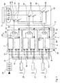
- FIG. 1 the basic structure of a control and regulation unit 1 for a safety-relevant device 3 is shown.
- a safety-relevant device 3 the triggering mechanism of an emergency slide in an aircraft is controlled or regulated.
- the emergency slide of an aircraft may only be triggered if very specific external conditions are present. For example, the door opening angle must have exceeded a certain size, since otherwise the emergency slide would be blown into the interior of the aircraft with unforeseeable consequences.
- the trigger mechanism for an emergency slide thus belongs to the highly safety-relevant devices of an aircraft.
- the control and regulation unit 1 shown is designed in 3-fold redundancy.
- Each computer unit 5 is configured as a programmable microprocessor, which has a number of computer inputs 8 and a number of interfaces 9, respectively, three times for carrying out logic operations.
- the computer inputs 8 are formed unidirectionally to supply of input signals.
- the interfaces 9 are bidirectionally designed for data exchange with other system units.
- Each circuit unit 7 has in each case unidirectional circuit inputs 10, via which input signals are likewise fed.
- electronic hardware components 12 a part of the logic operations that can be carried out in the computer units 5 is reproduced in each circuit unit 7.
- the circuit unit 7 will produce the same output as the computer unit 5 according to the simulated logic operation.
- a redundant, fail-safe architecture is achieved in which at the same time the occurrence of common-mode errors is reliably avoided.
- Redundant existing systems each consisting of a computer unit 5 and a circuit unit 7 are connected in parallel with respect to the input signals.
- the circuit unit 7 and the computer unit 5 are also connected in parallel with respect to the input signals.
- Each computer unit 5 is further via the interface 9 via a communication link 26 with other systems in data exchange.
- each computer unit 5 From each of the 3-fold signals of the proximity sensors 20, 21 and 22 and the triple microswitch 24, each computer unit 5 first selects by comparison the at least 2-fold matching signal for further processing. In addition, the output signals of the microswitch 24 and the proximity sensors 20, 21 and 22 are additionally compared. In the case of different output signals, the computer outputs 28 and circuit outputs 29 remain inactive. This is called a "fail-safe" behavior.
- each circuit unit 7 decides by hardware circuit by majority with respect to the incoming signals of the proximity sensors 20, 21 and 22 or of the 3-fold microswitch 24.
- each computer unit 5 From the input signals of the proximity sensors 20, 21 and 22 and the microswitch 24, an output signal is finally calculated in each computer unit 5, which represents a value for the degree of door opening.
- Each circuit unit 7 determined by appropriate hardware components a corresponding signal to the degree of door opening.
- the output signals determined in this way are respectively fed to a decision unit 30.
- This decision unit 30 determines the degree of correspondence between the output signals from the computer output 28 and the circuit output 29. If the match therefore provides identical signal information, then each decision unit 30 outputs a corresponding output signal, which is fed to a logic unit 32. If there is no match, the corresponding decision unit 30 generates no output signal.
- the output signals of each decision unit 30 are supplied to the logic unit 32 via the connection lines 33, 34 and 35.
- a signal is forwarded to the safety-relevant device 3 and thus to trigger the emergency slide by majority decision.
- the majority logic is represented by transistors 37, 38 and 39. If all 3 connecting lines 33, 34 and 35 show an output signal, then the transistors 37, 38 and 39 all turn on. As an output signal all lines 40, 41 and 42 are pulled to ground potential. If an output signal is generated only in the connecting lines 33 and 34, then only the transistors 37 turn on. As a result, only the line 40 is pulled to ground potential. The same applies to the lines 41 and 42 with matching output signals in the connecting lines 34 and 35 or 33 and 35th
- the emergency slide is triggered in the device 3 in accordance with majority decision.
- a light emitting diode display 44 is provided.
Landscapes
- Physics & Mathematics (AREA)
- General Physics & Mathematics (AREA)
- Engineering & Computer Science (AREA)
- Automation & Control Theory (AREA)
- Safety Devices In Control Systems (AREA)
Claims (5)
- Unité de commande et de régulation (1) pour un dispositif en rapport avec la sécurité (3), notamment en navigation aérienne, comprenant une unité de calcul (5) munie d'une pluralité d'entrées de calcul (8) et de sorties de calcul (28) et comprenant une unité de commutation (7) munie d'une pluralité d'entrées logiques (10) et de sorties logiques (29), caractérisée en ce que l'unité de commutation (7) simule au moyen de composants physiques (12) une partie des opérations logiques pouvant être effectuées dans l'unité de calcul (5), les entrées logiques (10) et les entrées de calcul (8) correspondant les unes aux autres du point de vue des opérations logiques simulées étant respectivement reliées en parallèle avec une ligne d'entrée de signal (13, 14, 15, 16), et les sorties de calcul (28) et les sorties logiques (29) correspondant les unes aux autres du point de vue des opérations logiques simulées étant respectivement reliées à une unité de décision (30) au moyen de laquelle peut être délivré un signal de sortie destiné à commander le dispositif en rapport avec la sécurité (3) en fonction de la concordance des signaux provenant de la sortie de calcul (28) et de la sortie logique (29).
- Unité de commande et de régulation (1) selon la revendication 1, la partie critique pour la sécurité des opérations logiques pouvant être effectuées dans l'unité de calcul (5) étant simulée au moyen de composants physiques (12) par l'unité de commutation (7).
- Unité de commande et de régulation (1) selon la revendication 1 ou 2, une pluralité d'unités de calcul (5), d'unités de commutation (7) et d'unités de décision (30) identiques étant présentes, les unités de calcul (5) et les unités de commutation (7) étant branchées parallèlement les unes aux autres par rapport aux lignes de signal (13, 14, 15, 16) et les sorties des unités de décision (30) étant reliées avec une unité logique (32) au moyen de laquelle peut être délivré un signal de commande destiné à commander le dispositif en rapport avec la sécurité (3) en fonction de la concordance des signaux de sortie.
- Unité de commande et de régulation (1) selon la revendication 3, les unités de calcul (5), unités de commutation (7) et unités de décision (30) étant présentes dans un nombre impair, notamment en triple, et l'unité logique (32) étant configurée pour délivrer le signal de commande conformément à une décision majoritaire concernant les signaux de sortie.
- Unité de commande et de régulation (1) selon l'une quelconque des revendications 1 à 4, une ou chacune des unités de calcul (5) étant conçue pour contrôler les signaux provenant des sorties logiques (29) et des sorties de calcul (28).
Applications Claiming Priority (1)
| Application Number | Priority Date | Filing Date | Title |
|---|---|---|---|
| DE102004033263A DE102004033263B4 (de) | 2004-07-09 | 2004-07-09 | Steuer-und Regeleinheit |
Publications (3)
| Publication Number | Publication Date |
|---|---|
| EP1615087A2 EP1615087A2 (fr) | 2006-01-11 |
| EP1615087A3 EP1615087A3 (fr) | 2006-06-14 |
| EP1615087B1 true EP1615087B1 (fr) | 2008-11-05 |
Family
ID=35169698
Family Applications (1)
| Application Number | Title | Priority Date | Filing Date |
|---|---|---|---|
| EP05014726A Ceased EP1615087B1 (fr) | 2004-07-09 | 2005-07-07 | Unité de commande et de régulation |
Country Status (3)
| Country | Link |
|---|---|
| US (1) | US7337020B2 (fr) |
| EP (1) | EP1615087B1 (fr) |
| DE (2) | DE102004033263B4 (fr) |
Families Citing this family (7)
| Publication number | Priority date | Publication date | Assignee | Title |
|---|---|---|---|---|
| US20100005657A1 (en) * | 2008-07-10 | 2010-01-14 | Van Vactor David R | Methods and systems to facilitate over-speed protection |
| US8321119B2 (en) * | 2008-07-10 | 2012-11-27 | General Electric Company | Methods and systems to facilitate over-speed protection |
| US8224552B2 (en) * | 2008-07-10 | 2012-07-17 | General Electric Company | Methods and systems to facilitate over-speed protection |
| FR3000196B1 (fr) * | 2012-12-21 | 2015-02-06 | Airbus Operations Sas | Dispositif de mise a disposition de valeurs de parametres de navigation d'un vehicule |
| US20140236457A1 (en) * | 2013-02-20 | 2014-08-21 | Xiamen King Long United Automotive Industry Co., Ltd. | Engine providing a self-adjusting system and a method to save fuel in accordance with a practical driving state of a vehicle |
| US9463873B2 (en) * | 2014-07-13 | 2016-10-11 | The Boeing Company | Vehicle braking system having braking control and skid reduction functions |
| US9522729B2 (en) * | 2014-07-18 | 2016-12-20 | Goodrich Corporation | Force command update rate detection |
Family Cites Families (14)
| Publication number | Priority date | Publication date | Assignee | Title |
|---|---|---|---|---|
| DE3208573C2 (de) * | 1982-03-10 | 1985-06-27 | Standard Elektrik Lorenz Ag, 7000 Stuttgart | 2 aus 3-Auswahleinrichtung für ein 3-Rechnersystem |
| DE3209718A1 (de) | 1982-03-17 | 1983-09-29 | M.A.N. Maschinenfabrik Augsburg-Nürnberg AG, 8000 München | Funktionssichere steuereinrichtung |
| JPS59212902A (ja) | 1983-05-18 | 1984-12-01 | Hitachi Ltd | 多重化制御装置 |
| US5880954A (en) * | 1995-12-04 | 1999-03-09 | Thomson; Robert | Continous real time safety-related control system |
| US5901927A (en) * | 1996-07-18 | 1999-05-11 | Honeywell Inc. | Ground strike protection function for aircraft autopilot |
| US6999824B2 (en) * | 1997-08-21 | 2006-02-14 | Fieldbus Foundation | System and method for implementing safety instrumented systems in a fieldbus architecture |
| DE59809233D1 (de) * | 1997-12-06 | 2003-09-11 | Elan Schaltelemente Gmbh & Co | Überwachungs- und steuergerät sowie verfahren zur überwachung einer technischen anlage mit erhöhten sicherheitsanforderungen, insbesondere eines handhabungsgerätes |
| US6909923B2 (en) * | 1999-12-22 | 2005-06-21 | Rockwell Automation Technologies, Inc. | Safety communication on a single backplane |
| US6701198B1 (en) * | 1999-12-22 | 2004-03-02 | Rockwell Automation Technologies, Inc. | Safety network for industrial controller allowing initialization on standard networks |
| US6629050B2 (en) * | 2001-02-13 | 2003-09-30 | Udt Sensors, Inc. | Vehicle safety and security system |
| DE10234303A1 (de) | 2002-07-26 | 2004-02-19 | Endress + Hauser Gmbh + Co. Kg | Vorrichtung zur Bestimmung und/oder Überwachung einer physikalischen oder chemischen Prozeßgröße |
| US6922625B2 (en) | 2002-12-12 | 2005-07-26 | Honeywell International Inc. | Jet engine control and protection system and method |
| US7213168B2 (en) * | 2003-09-16 | 2007-05-01 | Rockwell Automation Technologies, Inc. | Safety controller providing for execution of standard and safety control programs |
| US7117048B2 (en) * | 2003-09-30 | 2006-10-03 | Rockwell Automation Technologies, Inc. | Safety controller with safety response time monitoring |
-
2004
- 2004-07-09 DE DE102004033263A patent/DE102004033263B4/de not_active Expired - Fee Related
-
2005
- 2005-07-06 US US11/175,649 patent/US7337020B2/en not_active Expired - Fee Related
- 2005-07-07 DE DE502005005858T patent/DE502005005858D1/de not_active Expired - Lifetime
- 2005-07-07 EP EP05014726A patent/EP1615087B1/fr not_active Ceased
Also Published As
| Publication number | Publication date |
|---|---|
| EP1615087A2 (fr) | 2006-01-11 |
| DE502005005858D1 (de) | 2008-12-18 |
| EP1615087A3 (fr) | 2006-06-14 |
| US20060009958A1 (en) | 2006-01-12 |
| DE102004033263A1 (de) | 2006-01-26 |
| US7337020B2 (en) | 2008-02-26 |
| DE102004033263B4 (de) | 2007-07-26 |
Similar Documents
| Publication | Publication Date | Title |
|---|---|---|
| EP2550599B1 (fr) | Système d'ordinateur de commande, procédé de commande d'un système d'ordinateur de commande, et utilisation d'un système d'ordinateur de commande | |
| DE10152235B4 (de) | Verfahren zum Erkennen von Fehlern bei der Datenübertragung innerhalb eines CAN-Controllers und ein CAN-Controller zur Durchführung dieses Verfahrens | |
| DE69925000T2 (de) | Fehlertolerantes elektronisches bremssystem | |
| EP2765045A1 (fr) | Circuit de commande d'un système d'accélération, de freinage et de direction d'un véhicule | |
| EP1337921A1 (fr) | Dispositif de controle d'un processeur | |
| DE19509150C2 (de) | Verfahren zum Steuern und Regeln von Fahrzeug-Bremsanlagen sowie Fahrzeug-Bremsanlage | |
| EP1092177A1 (fr) | Regulateur ou regulateur de propulseur, propulseur et procede pour reguler un systeme de reglage ou d'entrainement ou un propulseur | |
| WO2022268270A1 (fr) | Dispositif de commande et système d'assistance pour un véhicule | |
| DE10211278A1 (de) | Verfahren zur Ansteuerung einer Komponente eines verteilten sicherheitsrelevanten Systems | |
| EP2648100B1 (fr) | Appareil d'automatisation doté de dispositifs de surveillance de processeurs | |
| EP1615087B1 (fr) | Unité de commande et de régulation | |
| DE102006013381B4 (de) | Steuervorrichtung für ein Kfz-Sicherheitssystem | |
| EP3073333B1 (fr) | Installation de brûleur avec un dispositif de sécurité | |
| DE4113959A1 (de) | Ueberwachungseinrichtung | |
| DE102021210600A1 (de) | System zum Bereitstellen eines Ausgangssignals basierend auf einem generierten Umfeldmodell eines Umfelds einer mobilen Plattform | |
| DE102011007467A1 (de) | Mehrkernige integrierte Mikroprozessorschaltung mit Prüfeinrichtung, Prüfverfahren und Verwendung | |
| DE10252990B3 (de) | Steuereinheit zur Auslösung eines Insassenschutzmittels in einem Kraftfahrzeug und Verfahren zur Überwachung der ordnungsgemäßen Funktion einer vorzugsweise solchen Steuereinheit | |
| DE102019218074A1 (de) | Steuerung eines Fahrerassistenzsystems eines Kraftfahrzeugs | |
| EP1649373A2 (fr) | Procede et dispositif pour la surveillance d'un systeme reparti | |
| DE102015215847B3 (de) | Vorrichtung und Verfahren zur Erhöhung der funktionalen Sicherheit in einem Fahrzeug. | |
| DE102006039671A1 (de) | Modulares elektronisches Flugsteuerungssystem | |
| DE102019216342B3 (de) | Auswertevorrichtung zur fehlertoleranten Auswertung von Sensorsignalen für ein Motorsteuergerät einer Kraftfahrzeuglenkung und Kraftfahrzeuglenkung | |
| EP1817662A2 (fr) | Procede et dispositif de commutation de mode de fonctionnement d'un systeme multiprocesseur par l'intermediaire d'au moins un signal externe | |
| WO2022263416A1 (fr) | Système de commande pour au moins un dispositif de réception dans des applications critiques en termes de sécurité | |
| DE102015119611B4 (de) | Verbesserung der Diagnostizierbarkeit von Fail-operational Systemen |
Legal Events
| Date | Code | Title | Description |
|---|---|---|---|
| PUAI | Public reference made under article 153(3) epc to a published international application that has entered the european phase |
Free format text: ORIGINAL CODE: 0009012 |
|
| AK | Designated contracting states |
Kind code of ref document: A2 Designated state(s): AT BE BG CH CY CZ DE DK EE ES FI FR GB GR HU IE IS IT LI LT LU LV MC NL PL PT RO SE SI SK TR |
|
| AX | Request for extension of the european patent |
Extension state: AL BA HR MK YU |
|
| PUAL | Search report despatched |
Free format text: ORIGINAL CODE: 0009013 |
|
| AK | Designated contracting states |
Kind code of ref document: A3 Designated state(s): AT BE BG CH CY CZ DE DK EE ES FI FR GB GR HU IE IS IT LI LT LU LV MC NL PL PT RO SE SI SK TR |
|
| AX | Request for extension of the european patent |
Extension state: AL BA HR MK YU |
|
| RAP1 | Party data changed (applicant data changed or rights of an application transferred) |
Owner name: DIEHL AEROSPACE GMBH |
|
| AKX | Designation fees paid | ||
| 17P | Request for examination filed |
Effective date: 20070131 |
|
| R17P | Request for examination filed (corrected) |
Effective date: 20070131 |
|
| RBV | Designated contracting states (corrected) |
Designated state(s): DE FR GB IT |
|
| 17Q | First examination report despatched |
Effective date: 20070326 |
|
| REG | Reference to a national code |
Ref country code: DE Ref legal event code: 8566 |
|
| GRAP | Despatch of communication of intention to grant a patent |
Free format text: ORIGINAL CODE: EPIDOSNIGR1 |
|
| GRAS | Grant fee paid |
Free format text: ORIGINAL CODE: EPIDOSNIGR3 |
|
| GRAA | (expected) grant |
Free format text: ORIGINAL CODE: 0009210 |
|
| AK | Designated contracting states |
Kind code of ref document: B1 Designated state(s): DE FR GB IT |
|
| REG | Reference to a national code |
Ref country code: GB Ref legal event code: FG4D Free format text: NOT ENGLISH |
|
| REF | Corresponds to: |
Ref document number: 502005005858 Country of ref document: DE Date of ref document: 20081218 Kind code of ref document: P |
|
| PLBE | No opposition filed within time limit |
Free format text: ORIGINAL CODE: 0009261 |
|
| STAA | Information on the status of an ep patent application or granted ep patent |
Free format text: STATUS: NO OPPOSITION FILED WITHIN TIME LIMIT |
|
| 26N | No opposition filed |
Effective date: 20090806 |
|
| REG | Reference to a national code |
Ref country code: FR Ref legal event code: PLFP Year of fee payment: 12 |
|
| PGFP | Annual fee paid to national office [announced via postgrant information from national office to epo] |
Ref country code: IT Payment date: 20160725 Year of fee payment: 12 Ref country code: GB Payment date: 20160721 Year of fee payment: 12 |
|
| REG | Reference to a national code |
Ref country code: FR Ref legal event code: PLFP Year of fee payment: 13 |
|
| GBPC | Gb: european patent ceased through non-payment of renewal fee |
Effective date: 20170707 |
|
| PG25 | Lapsed in a contracting state [announced via postgrant information from national office to epo] |
Ref country code: GB Free format text: LAPSE BECAUSE OF NON-PAYMENT OF DUE FEES Effective date: 20170707 |
|
| REG | Reference to a national code |
Ref country code: FR Ref legal event code: PLFP Year of fee payment: 14 |
|
| PG25 | Lapsed in a contracting state [announced via postgrant information from national office to epo] |
Ref country code: IT Free format text: LAPSE BECAUSE OF NON-PAYMENT OF DUE FEES Effective date: 20170707 |
|
| PGFP | Annual fee paid to national office [announced via postgrant information from national office to epo] |
Ref country code: FR Payment date: 20230725 Year of fee payment: 19 Ref country code: DE Payment date: 20230907 Year of fee payment: 19 |
|
| REG | Reference to a national code |
Ref country code: DE Ref legal event code: R119 Ref document number: 502005005858 Country of ref document: DE |
|
| PG25 | Lapsed in a contracting state [announced via postgrant information from national office to epo] |
Ref country code: DE Free format text: LAPSE BECAUSE OF NON-PAYMENT OF DUE FEES Effective date: 20250201 |
|
| PG25 | Lapsed in a contracting state [announced via postgrant information from national office to epo] |
Ref country code: FR Free format text: LAPSE BECAUSE OF NON-PAYMENT OF DUE FEES Effective date: 20240731 |