EP1615190A2 - Verfahren und Endgerät zur Erfassung und zum Ausgeben Verkehrssignalsinformation - Google Patents
Verfahren und Endgerät zur Erfassung und zum Ausgeben Verkehrssignalsinformation Download PDFInfo
- Publication number
- EP1615190A2 EP1615190A2 EP05014802A EP05014802A EP1615190A2 EP 1615190 A2 EP1615190 A2 EP 1615190A2 EP 05014802 A EP05014802 A EP 05014802A EP 05014802 A EP05014802 A EP 05014802A EP 1615190 A2 EP1615190 A2 EP 1615190A2
- Authority
- EP
- European Patent Office
- Prior art keywords
- traffic signal
- information
- image
- vehicle
- controller
- Prior art date
- Legal status (The legal status is an assumption and is not a legal conclusion. Google has not performed a legal analysis and makes no representation as to the accuracy of the status listed.)
- Granted
Links
Images


Classifications
-
- G—PHYSICS
- G08—SIGNALLING
- G08G—TRAFFIC CONTROL SYSTEMS
- G08G1/00—Traffic control systems for road vehicles
- G08G1/09—Arrangements for giving variable traffic instructions
- G08G1/0962—Arrangements for giving variable traffic instructions having an indicator mounted inside the vehicle, e.g. giving voice messages
- G08G1/0967—Systems involving transmission of highway information, e.g. weather, speed limits
- G08G1/096766—Systems involving transmission of highway information, e.g. weather, speed limits where the system is characterised by the origin of the information transmission
- G08G1/096791—Systems involving transmission of highway information, e.g. weather, speed limits where the system is characterised by the origin of the information transmission where the origin of the information is another vehicle
-
- G—PHYSICS
- G01—MEASURING; TESTING
- G01C—MEASURING DISTANCES, LEVELS OR BEARINGS; SURVEYING; NAVIGATION; GYROSCOPIC INSTRUMENTS; PHOTOGRAMMETRY OR VIDEOGRAMMETRY
- G01C21/00—Navigation; Navigational instruments not provided for in groups G01C1/00 - G01C19/00
- G01C21/26—Navigation; Navigational instruments not provided for in groups G01C1/00 - G01C19/00 specially adapted for navigation in a road network
- G01C21/34—Route searching; Route guidance
- G01C21/3407—Route searching; Route guidance specially adapted for specific applications
- G01C21/3415—Dynamic re-routing, e.g. recalculating the route when the user deviates from calculated route or after detecting real-time traffic data or accidents
-
- G—PHYSICS
- G01—MEASURING; TESTING
- G01C—MEASURING DISTANCES, LEVELS OR BEARINGS; SURVEYING; NAVIGATION; GYROSCOPIC INSTRUMENTS; PHOTOGRAMMETRY OR VIDEOGRAMMETRY
- G01C21/00—Navigation; Navigational instruments not provided for in groups G01C1/00 - G01C19/00
- G01C21/26—Navigation; Navigational instruments not provided for in groups G01C1/00 - G01C19/00 specially adapted for navigation in a road network
- G01C21/34—Route searching; Route guidance
- G01C21/36—Input/output arrangements for on-board computers
- G01C21/3602—Input other than that of destination using image analysis, e.g. detection of road signs, lanes, buildings, real preceding vehicles using a camera
-
- G—PHYSICS
- G08—SIGNALLING
- G08G—TRAFFIC CONTROL SYSTEMS
- G08G1/00—Traffic control systems for road vehicles
- G08G1/09—Arrangements for giving variable traffic instructions
- G08G1/0962—Arrangements for giving variable traffic instructions having an indicator mounted inside the vehicle, e.g. giving voice messages
- G08G1/0967—Systems involving transmission of highway information, e.g. weather, speed limits
- G08G1/096708—Systems involving transmission of highway information, e.g. weather, speed limits where the received information might be used to generate an automatic action on the vehicle control
- G08G1/096725—Systems involving transmission of highway information, e.g. weather, speed limits where the received information might be used to generate an automatic action on the vehicle control where the received information generates an automatic action on the vehicle control
-
- G—PHYSICS
- G08—SIGNALLING
- G08G—TRAFFIC CONTROL SYSTEMS
- G08G1/00—Traffic control systems for road vehicles
- G08G1/09—Arrangements for giving variable traffic instructions
- G08G1/0962—Arrangements for giving variable traffic instructions having an indicator mounted inside the vehicle, e.g. giving voice messages
- G08G1/0967—Systems involving transmission of highway information, e.g. weather, speed limits
- G08G1/096733—Systems involving transmission of highway information, e.g. weather, speed limits where a selection of the information might take place
- G08G1/096758—Systems involving transmission of highway information, e.g. weather, speed limits where a selection of the information might take place where no selection takes place on the transmitted or the received information
Definitions
- Related technical fields include methods of producing traffic signal information, a method of providing traffic signal information, and navigation apparatus.
- Conventional navigation apparatus search for a route from a current position to destination and display a detected route.
- Conventional navigation apparatus include map data, including road information and signal location information, stored on an external storage medium such as a hard disk or an optical disk.
- the conventional navigation apparatus display, on a display, a map indicating locations such as intersections where traffic signals are disposed.
- the navigation apparatus does not provide information associated with the status of the traffic signals.
- An in-vehicle camera system has been proposed to take an image of a signal using an in-vehicle camera (as disclosed, for example, Japanese Unexamined Patent Application Publication No. 11-306498). In this system, an image of a signal is compared with color information stored in a storage unit to identify the current color of the signal, and the various characteristic of the vehicle, such as the vehicle speed, is controlled based on the comparison.
- the above-described in-vehicle camera system does not have the capability of predicting how long the signal will remain in the current status or when the signal will change. That is, the system is capable of controlling the vehicle in accordance with the current status of a signal, but is not capable of providing information on a predicted waiting time at a signal or a predicted time at which the signal will change.
- the above-described in-vehicle camera system is not capable of providing information indicating whether to accelerate or decelerate the vehicle when the vehicle is approaching a signal. Additionally, the system does not provide information about a predicted waiting time at a red signal.
- various exemplary implementations of the principles described herein provide systems, apparatus, methods, and programs of producing and/or using traffic signal information that may take, when a vehicle is closely approaching a traffic signal, an image of traffic signal lamps disposed on the traffic signal.
- the systems, apparatus, methods, and programs may produce image data of the traffic signal lamps, based on the taken image and analyze the image data.
- the systems, apparatus, methods, and programs may produce traffic signal state information, the traffic signal state information including a state of the traffic signal as of the time of taking the image of the traffic signal lamps.
- the systems, apparatus, methods, and programs may store traffic signal information, the traffic signal information including the produced traffic signal state information, traffic signal location information, and time information in a memory.
- Fig. 1 is a block diagram showing a configuration of a navigation apparatus according to an exemplary implementation of the principles described herein;
- Fig. 2 is a diagram showing a vehicle having a navigation apparatus and approaching a signal
- Fig. 3 is a diagram showing a data structure of data stored in a memory of a navigation apparatus according to an exemplary implementation of the principles described herein;
- Fig. 4 shows a method of producing traffic signal information according an exemplary implementation of the principles described herein;
- Fig. 5 is a diagram showing data stored in a memory according to an exemplary implementation of the principles described herein;
- Fig. 6 is a diagram showing data stored in a memory according to an exemplary implementation of the principles described herein;
- Fig. 7 shows a method of according to an exemplary implementation of the principles described herein;
- Fig. 8 is a diagram showing a display according to an exemplary implementation of the principles described herein;
- Fig. 9 is a diagram showing a display according to an exemplary implementation of the principles described herein;
- Fig. 10 is a diagram showing data stored in a memory according to an exemplary implementation of the principles described herein;
- Fig. 11 shows a method of using traffic signal information according an exemplary implementation of the principles described herein.
- Fig. 12 is a diagram showing a display on a navigation apparatus according to an exemplary implementation of the principles described herein;
- Fig. 13 shows a method of using traffic signal information according an exemplary implementation of the principles described herein;
- Fig. 14 shows a method of using traffic signal information according an exemplary implementation of the principles described herein;
- Fig. 15 is a diagram showing a display according to an exemplary implementation of the principles described herein;
- Fig. 16 shows a method of using traffic signal information according an exemplary implementation of the principles described herein;
- Fig. 17 is a diagram showing a display according to an exemplary implementation of the principles described herein;
- Fig. 18 is a diagram showing a system according to an exemplary implementation of the principles described herein.
- Fig. 19 is a diagram showing a display according to an exemplary implementation of the principles described herein.
- Fig. 1 is a block diagram showing an exemplary configuration of a navigation apparatus 1.
- the navigation apparatus 1 may serve as an in-vehicle terminal installed in a vehicle, for example car C.
- the navigation apparatus 1 may physically, functionally, and/or conceptually include a controller 2.
- the controller 2 may perform route guidance, for example based on instructions. Route guidance may include searching for a route from a current position to a destination and outputting a map including a detected route.
- the controller 2 may transmit and/or receive various kinds of data to/from, for example, an electronic control unit (ECU) 30 of the car C.
- ECU electronice control unit
- Instructions, including the route guidance instructions may be stored in a memory 4 that may be connected to the controller 2, for example, via a bus BS.
- the memory 4 may also store map attribute information including, for example, node data, road information, and traffic signal location information.
- map attribute information including, for example, node data, road information, and traffic signal location information.
- display data that may be used to display various kinds of screens on, for example, a display 3 may also be stored in the memory 4.
- the memory may include, for example, a RAM, a ROM, and/or an external storage medium, such as, for example, an optical disk.
- the navigation apparatus 1 may include, for example, a vehicle speed sensor 5, a direction sensor 6, and/or a GPS receiver 7. Based on detection signals output from one or more of the vehicle speed sensor 5, the direction sensor 6, and/or the GPS receiver 7, the controller 2 may detect the position of the car C.
- the navigation apparatus 1 may also include, for example, a traffic signal memory 10.
- the traffic signal memory 10 may store, for example, traffic signal information associated with each on-road traffic signal S (e.g., shown in Fig. 2), in form of, for example, a database.
- the navigation apparatus 1 may further include, for example, an input unit SW that may have, for example, switches, button, keys, and/or a touch screen for use by a user to specify a route guiding/searching condition such as a destination.
- a camera 20 may be connected to the navigation apparatus 1.
- the camera 20 may be capable of transmitting and/or receiving data to/from the controller 2 of the navigation apparatus 1.
- a color CCD camera may be used as the camera 20.
- the camera 20 may be disposed on the outer surface of the car C or disposed inside the car C at a location close to the windshield capture a traffic signal within a predetermined angle.
- the camera 20 may include a driver unit (not shown), for example, capable of controlling the orientation of an imaging lens in accordance with a control signal supplied from the controller 2. As shown in Fig.
- the camera 20 may take an image of the traffic signal lamps L of the traffic signal S, for example, under the control of the controller 2.
- the combination of the camera 20 and the navigation apparatus 1 may form a traffic signal information generation system SY.
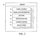
- Fig. 3 shows an exemplary data structure of traffic signal information 11, for example, stored in the traffic signal memory 10.
- the traffic signal information 11 may be information associated with traffic signals such as, for example, the traffic signal S. Each time the car C passes by a traffic signal S, the traffic signal information 11 may be produced for that traffic signal S.
- the traffic signal information 11 may be physically, functionally, and/or conceptually divided into, for example, traffic signal location information 12, traffic signal state information 13, date/time information 14, driving direction information 15, current position information 16, and/or vehicle speed information 17.
- the traffic signal location 12 may include three-dimensional coordinate data indicating the position and the height of the location where the traffic signal S is installed, and the traffic signal location 12 may correspond to a node or a link of the node data.
- each road may consist of a plurality of componential units called links.
- Each link may be separated and defined by, for example, an intersection, an intersection having more than three roads, a curve, and/or a point at which the road type changes.
- node refers to a point connecting two links.
- a node may be, for example, an intersection, an intersection having more than three roads, a curve, and/or a point at which the road type changes
- the traffic signal state information 13 may include information indicating the status, such as the color, of the traffic signal lamp L or the status of an arrow lamp indicating the right turn or the like of the traffic signal S when the car C is approaching the traffic signal S.
- the date/time 14 may include information indicating, of r example, the year, month, day, and time at which the image of the traffic signal lamp L of the traffic signal S was taken. The time may be represented in hours, minutes, and seconds.
- the driving direction 15 may indicate the direction of the car C when the image of the traffic signal lamp L is taken.
- the current position 16 may indicate the position of the car C when the image of the traffic signal lamp L is taken.
- the vehicle speed 17 may indicate the speed of the car C when the image of the traffic signal lamp L is taken.
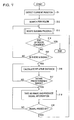
- An exemplary method of producing traffic signal information 11 is described below with reference to Figs. 4 to 6.
- the exemplary method may be implemented, for example, by the above-described traffic signal information generation system SY.
- the exemplary method need not be limited by any of the above-described structure.
- a route to a specified destination may be searched for.
- the route may be searched for, for example, by the navigation apparatus 1.
- a current position is detected, for example, using the GPS receiver 7 under control of the controller 2 (step S1-1).
- a navigation route from the current position to a destination is searched for (step S1-2).
- the destination may be indicated by destination information input by a user via the input unit SW, and the route may be searched for under control of the controller 2 by using data including node data and/or link data stored in the memory 4.
- route guidance is performed (step S1-3), for example by the controller 2.
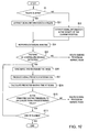
- it is determined whether route guidance is complete (sep S1-4) and whether there is a traffic signal S ahead of the car C (step S1-5).
- map attribute information for an area with a size of, for example about a few hundred to about a few thousand meters including the current position of the car C may be extracted, and the determination may be made based on the current position and the traffic signal location information included in the extracted map attribute information.
- step S1-5 YES
- the distance between the car C and the traffic signal S is calculated(step S1-6), for example, by the controller 2, to determine whether the car C is within a predetermined range of the traffic signal S (step S1-7).
- step S1-7 YES
- an image of traffic signal lamps L of the traffic signal S is taken at predetermined intervals (e.g., of about one sec), for example, by the camera 20 under control of the controller 2.
- the traffic signal image (image data) is then used to generate traffic signal information (step S1-8).
- the controller 2 may acquire the traffic signal images taken at intervals of about one sec.
- the controller 2 may produce the traffic signal information associated with the traffic signal S and may store the produced traffic signal information in, for example, the traffic signal memory 10.
- a piece of traffic signal information 11 may be produced and stored including, for example, the traffic signal location 12, the traffic signal state information 13, the date/time 14 of taking the image, the driving direction 15, the current position 16 of the vehicle, and/or the vehicle speed 17 as of when the image was taken.
- a pieces of traffic signal information 11 may be produced for each times the image of traffic signal S is taken. That is, if the car C is stopped at a red traffic signal or is stopped before a traffic signal by a traffic jam, a greater number of images of a traffic signal S are taken and a greater number of pieces of traffic signal information 11 are produced.
- the traffic signal S is in a green-state and thus the car C passes by the traffic signal S without stopping at the traffic signal S, a smaller number of pieces of traffic signal information 11 may be produced.
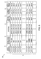
- traffic signal information 11 associated with each traffic signal S (e.g., shown in Fig. 5) is produced and, for example, stored in the traffic signal memory 10. Additional traffic signal information 11 may also be produced for a same traffic signal S if the car C passes by that same traffic signal S at any different time. Thus, traffic signal information 11 may be accumulated, for example, in the traffic signal memory 10 and, for example, a database DB associated with the traffic signal S may be produced.
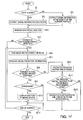
- exemplary process of providing guidance information associated with traffic signals based on traffic signal information 11 is described below with reference to Fig. 7.
- the exemplary method may be implemented, for example, by the above-described navigation apparatus 1.
- the exemplary method need not be limited by any of the above-described structure.
- step S2-1 it is determined whether to provide route guidance to a destination (step S2-1). This determination may be made by the controller 2, for example, by checking whether a guidance operation is set in the route guidance mode via the input unit SW.
- the traffic signal information 11 associated with a traffic signal S on the navigation route is extracted from the traffic signal memory 10 (step S2-2).
- the controller 2 may extract the traffic signal location information corresponding to the traffic signal S on the navigation route, based on the map attribute information stored in the memory 4 and the navigation route to the destination. Then, the controller 2 may search the traffic signal memory 10 for the traffic signal information 11 including the same traffic signal location 12 as the extracted traffic signal location information. If the controller 2 finds such traffic signal information 11, the controller 2 may read the traffic signal information 11 from the traffic signal memory 10.
- the controller 2 may detect the traffic signal location of each traffic signal close to the current position, based on map attribute information and information indicating the current position of the car C acquired from the GPS receiver 7.
- the controller 2 may read the traffic signal information 11 corresponding to each of all detected traffic signal locations from the traffic signal memory 10.
- the controller 2 may perform a statistical analysis on the traffic signal state information 13 and/or the date/time information 14 described in the traffic signal information 11 in accordance with, for example, statistical analysis instructions stored in the memory 4 in order to predict the most likely state of the traffic signal S from the statistically likely state of the traffic signal S at the same time as the predicted time at which the car C will arrive at the traffic signal S.
- a traffic signal S may be predicted to be in the green-state at 8:00.
- the controller 2 may start performing a statistical analysis for another traffic signal S.
- the controller 2 may determine, for example, the intervals at which the status of the traffic signal lamp L is switched (in the order red, yellow, green) and/or the on-period for each color (for example, about 60 sec for a red traffic signal).
- the controller 2 may determine that it is unlikely to statistically determine the intervals and/or the on-period, and the controller 2 may start performing a statistical analysis for another traffic signal S.
- the controller 2 may determine whether there is a correlation with an adjacent traffic signal S based on the traffic signal information 11. For example, in some cases, when there are traffic signals S respectively located at successive intersections, these traffic signals are controlled such that change-timing of the state thereof is shifted by, for example, about 10 sec. from one traffic signal to another so that cars can run more smoothly. Thus, the controller 2 may determine the statistical correlation between one traffic signal S and other adjacent traffic signals S.
- the controller 2 may also determine whether the switching intervals and/or the on-period are controlled differently depending on the time zone. In some cases, for example, the switching intervals and/or the on-period of a traffic signal are controlled differently depending on whether the current time is in a rush-hour zone or a low-traffic zone. Thus, the controller 2 may determine whether the traffic signal S is operated in a yellow-blinking mode during a particular time zone by making a statistical comparison among plural pieces of traffic pattern information.
- step S2-5 If there is a particular control pattern for the traffic signal S (that is, if the answer to step S2-5 is yes), it is determined whether the distance from the current position of the car C to the traffic signal S is within a predetermined range. If so, an image of the traffic signal lamp L is taken, for example, by the camera 20 under control of the controller 2 (step S2-6). Then image recognition is performed based on the image transmitted from the camera 20. Based on the result of the image recognition, traffic signal information 11 including traffic signal state information 13 is produced, for example, by the controller 2 and stored in the traffic signal memory 10.
- Traffic signal prediction information is produced based on the traffic signal control pattern and the traffic signal state information 13 (step S2-7).
- the traffic signal prediction information may include information indicating a predicted time when the traffic signal S will change and a predicted duration during which the traffic signal S will remain unchanged.
- the traffic signal prediction information may be produced by the controller 2 based on the detected traffic signal control pattern as described below.
- the value of the switching interval of the traffic signal state and the durations of respective traffic signal states may be extracted from the produced traffic signal state information (e.g., produced in step S2-6) may be employed as initial values, and values of the switching interval and the durations of respective traffic signal states of the traffic signal S may be added to the initial values. Then, the time at which the traffic signal S changes into the yellow-state from the red-state, the time at which the traffic signal S changes from the yellow-state into the green-state, the time at which the traffic signal S changes from the red-state into the right-turn-permission state, the duration of the red-state, the duration of the yellow-state, the duration of the green-state, and/or the duration of the right-turn-permission state may be calculated for as many samples as possible.
- step S2-8) it is determined whether it is possible to pass by the traffic signal S of interest without stopping. Specifically, for example, if the controller 2 determines (e.g., in step S2-6) that the traffic signal lamp L is in the red-state, then the controller 2 may determine that it is not allowed to pass by the traffic signal S without stopping.
- the controller 2 may calculate the predicted time necessary for the car C to arrive at the traffic signal S, based on, for example, the current vehicle speed, the current position, and/or the traffic signal location information. The controller 2 may compare the predicted necessary time with the traffic signal prediction information. If the predicted necessary time is longer than the time which the traffic signal S will remain unchanged but within the time in which the traffic signal S will be switched into the red-state, the controller 2 may determine that it is impossible to pass the traffic signal S without stopping. On the other hand, when the predicted necessary time is shorter than the time during which the traffic signal S will remain unchanged, the controller 2 may determine that it possible to pass by the traffic signal S without stopping.
- the controller 2 may add the duration of the right-turn-permission state to the duration until the transition into the red-state to calculate the total available time.
- step S2-8 YES
- step S2-9 YES
- the controller 2 may extract, from the traffic signal prediction information, the time during which the arrow-lamp mode is maintained. Then the predicted time is output (step S2-10).
- the controller 2 may output via an electronic control unit 30, the predicted time on a display 31 (e.g., Fig. 1 or 8) serving as the display means disposed on a meter panel P of the car C.
- step S2-11 the controller 2 may calculate a distance to a car running ahead of the car C by using a car-to-car distance sensor (not shown) disposed on the front side of the car C. The controller 2 may then calculate the speed reduction rate at which the vehicle speed should be reduced, based on, for example, the distance from the current position of the car C to the traffic signal S, the time at which the traffic signal lamp L will be changed into the red-state, the current vehicle speed, and the car-to-car distance.
- the speed reduction rate and/or traffic signal guide information is ten displayed (step S2-12).
- the controller 2 displays traffic signal guide information including a message "the traffic signal is going to change into the red-state" and the speed reduction rate on the display 31, as shown, for example, in Fig. 9.
- the controller 2 may repeatedly perform the above-described process of providing guiding information on traffic signals S on the navigation route or in an area in the vicinity of the current position of the car C.
- the controller 2 may repeats the above-described process to detect a traffic signal S located ahead of the car C and provide guidance information associated with detected traffic signal S.
- the navigation apparatus 1 installed in the car C may be connected to the camera 20 installed in the car C.
- the controller 20 may transmit a control traffic signal to the camera 20 in accordance with the traffic signal location information stored in the memory 4 to take an image of the traffic signal lamp L of the traffic signal S.
- the navigation apparatus 1 may analyze (by means of image recognition) the image data output from the camera 20 and may produces traffic signal state information 13 identifying the traffic signal status.
- the produced traffic signal state information 13 may be stored together with traffic signal location information 12 and the date/time information 14, as traffic signal information 11, in the traffic signal memory 10.
- traffic signal information 11 associated with the traffic signal S as of that time may be produced, and thus traffic signal information 11 associated with each traffic signal S may be accumulated in the database associated with traffic signals. Based on this database, it is possible to calculate, for example, the intervals at which the traffic signal state changes, the length of each state of each traffic signal S, the dependence of these parameters on the time, etc., and/or provide information associated with traffic signals to a user.
- the camera 20 may take an image of the traffic signal S a plurality of times at intervals of about 1 sec.
- a lot of traffic signal information 11 may be collected in the database, and, based on the data collected in the database; it is possible to predict the status of the traffic signal S when the car C arrives at the traffic signal S. It is also possible to predict the period during which the traffic signal S is maintained in a particular status.
- the navigation apparatus 1 may statistically analyze a plurality of pieces of traffic signal information 11 to extract a traffic signal control pattern of each traffic signal S, and may produces traffic signal prediction information in terms of the duration of each state of the traffic signal lamp L based on the extracted traffic signal control pattern. Based on the traffic signal prediction information, it is possible to display, on the display 31, information indicating when the traffic signal will change into the red-state or information indicating the time at which a right turn will be permitted. This prevents a vehicle from being suddenly stopped by an unexpected change of a traffic signal into a red-state, or quickly accelerated when a traffic signal changes into the red-state in the middle of an intersection. Furthermore, it becomes possible to prevent a driver from waiting at a traffic signal even after the traffic signal has changed into a green-state without noticing the change.
- the navigation apparatus 1 may detect the location of each traffic signal on a navigation route from a current position to a destination or in the vicinity of the current position. Furthermore, when the traffic signal location is detected, the navigation apparatus 1 may determine whether the distance between the car C and the traffic signal location is within a range that allows the camera 20 to take an image of the traffic signal. If so, the navigation apparatus 1 may transmit a control traffic signal to the camera 20 to take an image of the traffic signal. This allows a reduction in the amount of data stored in the navigation apparatus 1, and the camera 20 does not need to have a capability of detecting a traffic signal. The prediction of the traffic signal location ensures that the camera 20 can take an image of the traffic signal without failure. It is also possible to achieve a reduction in the time needed for the camera 20 to perform image recognition, an increase in recognition rate, and a reduction in processing load imposed on the navigation apparatus 1.
- the controller 2 of the navigation apparatus 1 may stores the traffic signal information 11 in the traffic signal memory 10.
- predetermined intervals e.g., of about 1 sec
- the produced image data may be sequentially transmitted together with data indicating the date/time of taking the image to the controller 2. If the controller 2 receives the image data and the date/time data, the controller 2 may analyze the received image data. The controller 2 may store, as traffic signal information 11, the traffic signal state information 13 obtained from the first image together with the date/time 14, the traffic signal location 12, etc. in the traffic signal memory 10, in the top row thereof as shown in Fig. 10.
- the controller 2 may analyze each image sequentially taken thereafter.
- the controller 2 may compare the traffic signal state information 13 produced based on the analysis of each image data (indicating, for example, the yellow-state) with the traffic signal state information 13 of the first traffic signal information 11 (indicating, for example the yellow-state) to determine whether a change in the traffic signal state has occurred.
- the controller 2 may determines that no change has occurred in the traffic signal state. In this case, the controller 2 may not store the traffic signal state information 13 corresponding to second or following image data and will analyze the next image and compares the analysis result with the first traffic signal state information 13.
- the controller 2 determines that a change in the traffic signal status has occurred, and the controller 2 stores the traffic signal state information 13 thereof together with the associated data such as the date/time 14 in the traffic signal memory 10.
- the different traffic signal information 11 is stored in a data area next to the first traffic signal information 11.
- the different traffic signal information 11 is stored in the second row.
- the controller 2 may sequentially analyze images taken by the camera 20 and may store traffic signal information 11 in the traffic signal memory 10 only when a change in the traffic signal status occurs. In this way, a database DB associated with traffic signal information 11 is produced.
- the second example provides the following advantage in addition to the advantages provided by the first example.
- the controller 2 when the controller 2 of the navigation apparatus 1 sequentially analyzes images, the controller 2 stores traffic signal information 11 only if the controller 2 detects a difference in the traffic signal status from the first image, i.e., having traffic signal state information 13 different from the traffic signal state information 13. That is, when the controller 2 detects a change in the traffic signal status, the controller 2 may store traffic signal information 11.
- the controller 2 may store traffic signal information 11.
- a detour may be searched for.
- step S2-14 the predicted period during which the car C will be stopped. Specifically, based on the traffic signal prediction information, the controller 2 may calculate the predicted time during which the car C has to wait until the traffic signal changes into the green-state from the red-state.
- the controller 2 may than calculate the predicted time needed to run along the detour, based on, for example, the length of the detour. The controller 2 may then compare the time needed to travel to the destination via the detour and the time needed to travel to the destination along the original route including the traffic signal S. Note that the time needed when the original route is taken includes the waiting time at the traffic signal S.
- the method may proceed in accordance with the above example(s).
- the controller 2 may output the detour route.
- the controller 2 may displays a message such as "detour is recommended" on the display 31.
- the controller 2 may display a map including the detour route on the display 3.
- a map screen G including the detour route highlighted by color is displayed on the display 3.
- the navigation apparatus 1 may search for a detour to avoid the long waiting time at the red traffic signal.
- the navigation apparatus 1 may display the detected detour route on the display 3 of the navigation apparatus 1.
- a database DB based on the traffic signal information 11 may be produced, for example, by the controller 2 and accumulated in the traffic signal memory 10 (step S1-10).
- the controller 2 may perform a statistical analysis on the traffic signal information 11 (e.g., acquired in step S1-8).
- the traffic signal information 11 may be stored in the past to determine the dependence of the control of the traffic signal state on the time, the intervals at which the traffic signal state is switched, and the duration period of each traffic signal state. Furthermore, the controller 2 may determine whether there is a correlation in the manner of controlling the traffic signal state between a traffic signal and an adjacent traffic signal S. If a correlation is detected, the controller 2 may produce data indicting the correlation by, for example, a value or an equation. When the controller 2 obtains data indicating the statistical dependence of the manner of controlling the traffic signal state on the time, the controller 2 may store the obtained data such that the data is linked to the traffic signal information 11.
- the controller 2 may searches for correlation data linked to traffic signal information 11 to determine whether there is a correlation in terms of the manner of controlling the traffic signal state between the current traffic signal S, which will be passed, and an adjacent traffic signal S. If a correlation is detected, the controller 2 may determines whether it is possible to pass by both the current traffic signal S and the adjacent traffic signal S without stopping, based on the data indicating the statistical dependence of the manner of controlling the traffic signal state on the time.
- step S2-8 NO
- the controller 2 may then advances the process to (e.g., to step S2-11) to calculate the speed reduction rate.
- step S2-11 the controller 2 may also determine which one of the traffic signal S cannot be passed by without stopping. For example, based on the vehicle speed and the distance to the traffic signal S, the controller 2 may determine, for example, that it is possible to pass by the current traffic signal S without stopping but is impossible to pass by the next traffic signal S without stopping. The controller 2 may then calculate the vehicle speed necessary to pass by the current traffic signal S and then stop at the next traffic signal S.
- the controller 2 may then output the traffic signal guide information indicating the corresponding speed reduction rate.
- the traffic signal guide information displayed on the display 31 may include, for example, a message "a first traffic signal can be passed by without stopping, but a next traffic signal cannot be passed by without stopping.”
- the traffic signal guide information may include such information.
- the controller 2 of the navigation apparatus 1 may perform a statistical analysis on the traffic signal information 11 associated with respective adjacent traffic signals S to detect the correlation in terms of the manner of controlling the status of the traffic signal lamp L among adjacent traffic signals S.
- the controller 2 may produce data indicating the detected correlation.
- the controller 2 may produce traffic signal guide information associated with each traffic signal S and may display it on the display 31.
- That traffic signal guide information may be displayed when the camera 20 cannot capture an image of a traffic signal lamp L because of an obstacle such as a large-size vehicle running ahead of the car C.
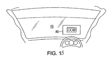
- the projector may projects traffic signal guide information onto a semitransparent reflecting sheet RS serving as display means disposed, for example, on a windshield FG of the car C such that an image of a traffic signal is displayed on the reflecting sheet RS and thus a user can view the image of the traffic signal.
- Information of the car location may also be displayed on the reflecting sheet RS to show the distance between the car C and the traffic signal S.
- a message indicating whether or not the car C can pass by the traffic signal S without stopping may also be displayed.
- step S2-14 NO
- the controller 2 may provide route guidance in the normal mode.
- traffic signal guide information based on traffic signal prediction information may be displayed on the reflecting sheet RS.
- the controller 2 of the navigation apparatus 1 may analyze the image data output from the camera 20 to determine whether it is possible to recognize the state of the traffic signal lamp L of a traffic signal S. If it is impossible to recognize the state of the traffic signal lamp L, traffic signal guide information associated with the traffic signal S may be displayed on the windshield FG. This makes it possible to provide information associated with the traffic signal S located ahead of the car C when a driver cannot directly view the traffic signal S because of an obstacle such as a large-size vehicle. This prevents a vehicle from being suddenly stopped by an unexpected change of a traffic signal into a red-state, or quickly accelerated when a traffic signal changes into the red-state in the middle of an intersection. Thus, the drive can safely drive a car in accordance with the traffic signal guide information.
- Traffic signal guide information may be displayed when the camera 20 cannot capture an image of a traffic signal lamp L because of an obstacle such as a large-size vehicle running ahead of the car C. That traffic signal guide information may be displayed when running-ahead-vehicle detector detects a large-size vehicle running ahead of the car C.
- the determination as to whether there is a large-size vehicle may be made by analyzing image data output from the camera 20.
- the controller 2 may calculate the car-to-car distance based on a detection traffic signal output from a car-to-car distance detector, such as, for example, a laser radar, a millimeter-wave radar, or an ultrasonic sonar disposed on the car C. Then the controller 2 may determine that there is a large-size vehicle running ahead of the car C only when the detected car-to-car distance is less than a predetermined value.
- step S2-17 YES
- traffic signal guide information my be displayed (step S2-18).
- step S2-17 NO
- the controller 2 performs the route guiding process in accordance with the above examples.
- the controller 2 of the navigation apparatus 1 my analyze the image data output from the camera 20 to determine whether there is a large-size vehicle running ahead of the car C. If a large-size vehicle running ahead is detected, traffic signal guide information associated with the traffic signal S may be displayed on the windshield FG. This makes it possible to provide information associated with the traffic signal S located ahead of the car C when a driver cannot directly view the traffic signal S because of an obstacle such as a large-size vehicle. This prevents a vehicle from being suddenly stopped by an unexpected change of a traffic signal into a red-state, or quickly accelerated when a traffic signal changes into the red state in the middle of an intersection. Thus, the driver can safely drive a car in accordance with the traffic signal guide information.
- the predicted waiting time at the traffic signal S may be calculated, and the car C may be controlled depending on the predicted waiting time.
- the controller 2 may calculates the predicted waiting time at the traffic signal (step S2-19). For example, based on the traffic signal prediction information, the controller 2 may calculate the predicted period from a time at which the car C will stop to a time at which the green-signal lamp L indicating the permission of passing through the intersection is lit.
- a predetermined value example, e.g., about 60 sec
- the seventh example provides the following advantages.
- the controller 2 of the navigation apparatus 1 may calculate the predicted waiting time at the traffic signal S based on the statistical analysis on the traffic signal information 11 associated with the traffic signal S. If the predicted waiting time is equal to or longer than the predetermined value, the control command may be transmitted to the electronic control unit 30 of the car C. For example, when the predicted waiting time at a traffic signal is long, the operation of the car C is controlled in terms of braking or stopping of idling.
- the image recognition of the traffic signal may be omitted and the determination (in step S2-8) as to whether the car C can pass by the traffic signal S may be made without performing the image recognition of the traffic signal (step S2-6).
- the controller 2 may extracts the newest traffic signal information 11 associated with traffic signal S and employs the traffic signal state information 13 and the date/time information 14 thereof as initial values. The controller 2 may then calculate the predicted status at the current time based on the time from that date/time to the current time, the switching intervals of the traffic signal state, and/or durations of respective traffic signal states.
- the traffic signal S was in the blue state at 9:00:10 on the day before the current day, the elapsed time from that time to the current time is calculated, and the current state of the traffic signal is predicted, for example, by dividing the elapsed time by the repetition period of the traffic signal.
- the controller 2 may search for a route (step S1-2) and may produce traffic signal information 11 when the car C is running along the determined route.
- searching for a route may be omitted, and the traffic signal information 11 may be produced when the car C is running on an arbitrary road.
- the traffic signal location 12 does not necessarily need to be given in the form of 3-dimensional coordinate data, but the traffic signal location 12 may be given in the form of 2-dimensional data that does not have a component indicating the height of the traffic signal lamp L, especially where the height of the lamp L is standardized.
- the driving mechanism of the camera 20 for controlling the orientation of the imaging lens may also be omitted.
- a detour route may be automatically displayed on the display 3.
- the controller 2 may automatically control braking of the car C via the electronic control unit 30 in accordance with traffic signal prediction information.
- the gear selection or stopping idling may be automatically performed via the electronic control unit 30.
- the navigation apparatus 1 may be connected to a control server in the traffic signal information generation system.
- the navigation apparatus 1 installed in the car C may be connected to the control server SV via the network N.
- the control server SV may collect traffic signal information 11 from a plurality of navigation apparatus 1 and may store the collected traffic signal information 11 in the database DB.
- a large number of pieces of traffic signal information 11 are collected from many cars, and the collected information is managed at the control server SV.
- the navigation apparatus 1 may access the database DB stored in the control server SV to acquire the traffic signal information 11 associated with that traffic signal S.
- the analysis of images and producing of the traffic signal information 11 may not be performed not by the controller 2 of the navigation apparatus 1 but may be performed by the control server SV.
- the controller 2 may calculate the predicated waiting time at each traffic signal on the route, based on the traffic signal information 11 associated with each traffic signal, and may select an optimum route that, for example, needs a shortest time to get to the destination, that needs a lowest consumption of gas, and/or that needs a least number of times the car C stops at red traffic signals.
- the controller 2 may calculate an optimum start time that allows it to reach a destination in a shortest time and may recommend the optimum start time to a user.
- the traffic signal guide information may be projected on an inner surface of a windshield.
- a projector (not shown) capable of transmitting and/or receiving data to/from the navigation apparatus 1 is installed inside the car C, and a semitransparent reflecting sheet RS is stuck on the windshield FG, as shown, for example, in Fig. 19.
- the projector may project traffic signal guide information onto the reflecting sheet RS to display the traffic signal guide information on the reflecting sheet RS. This makes it possible for a driver to view the traffic signal guide information without moving the direction of view.
- the controller 2 may analyze motion image data output from the camera 20.
- the camera 20 may have an image recognition capability to recognize an image of a traffic signal S.
- the camera 20 may includes a controller that analyzes image data produced by an imaging part and transmits data indicating an analysis result to the controller 2 of the navigation apparatus 1. This may allow a reduction in the processing load imposed on the navigation apparatus 1.
- the traffic signal guide information indicating switching of a traffic signal status, a predicted waiting time at a traffic signal, etc. to be notified to a user may be output in the form of a voice from a speaker of the navigation apparatus 1 or may be displayed on the display 3 of the navigation apparatus 1.
- traffic signal information 11 is produced by the navigation apparatus 1
- the traffic signal information 11 may be produced by an apparatus that does not have a capability of searching for a route but that has at least a capability of detecting a current position (GPS receiver 7), a capability of transmitting and/or receiving data to/from the camera 20, a storage unit for storing traffic signal location information, and a storage unit for storing traffic signal information. This allows a reduction in the processing load imposed on the navigation apparatus.
- traffic signal guide information is displayed on the windshield FG of the car C
- the traffic signal guide information may be displayed on the display 31, for example, disposed on the instrument panel or the display 3 of the navigation apparatus 1.
- Systems, methods, and programs of producing and using traffic signal information take, when a vehicle is closely approaching a traffic signal, an image of traffic signal lamps disposed on the traffic signal.
- the systems, methods, and programs produce image data of the traffic signal lamps, based on the taken image and analyze the image data.
- the systems, methods, and programs produce traffic signal state information, the traffic signal state information including a state of the traffic signal as of the time of taking the image of the traffic signal lamps.
- the systems, methods, and programs store traffic signal information, the traffic signal information including the produced traffic signal state information, traffic signal location information, and time information in a memory.
Landscapes
- General Physics & Mathematics (AREA)
- Physics & Mathematics (AREA)
- Engineering & Computer Science (AREA)
- Remote Sensing (AREA)
- Radar, Positioning & Navigation (AREA)
- Life Sciences & Earth Sciences (AREA)
- Atmospheric Sciences (AREA)
- Automation & Control Theory (AREA)
- Computer Vision & Pattern Recognition (AREA)
- Navigation (AREA)
- Traffic Control Systems (AREA)
- Circuits Of Receivers In General (AREA)
- Devices For Checking Fares Or Tickets At Control Points (AREA)
Priority Applications (1)
| Application Number | Priority Date | Filing Date | Title |
|---|---|---|---|
| EP08159232A EP1968030B1 (de) | 2004-07-09 | 2005-07-07 | Verfahren und Endgerät zur Erfassung und zum Ausgeben von Verkehrssignalsinformationen |
Applications Claiming Priority (2)
| Application Number | Priority Date | Filing Date | Title |
|---|---|---|---|
| JP2004203524 | 2004-07-09 | ||
| JP2004300437A JP4507815B2 (ja) | 2004-07-09 | 2004-10-14 | 信号情報作成方法、信号案内情報提供方法及びナビゲーション装置 |
Related Child Applications (1)
| Application Number | Title | Priority Date | Filing Date |
|---|---|---|---|
| EP08159232A Division EP1968030B1 (de) | 2004-07-09 | 2005-07-07 | Verfahren und Endgerät zur Erfassung und zum Ausgeben von Verkehrssignalsinformationen |
Publications (3)
| Publication Number | Publication Date |
|---|---|
| EP1615190A2 true EP1615190A2 (de) | 2006-01-11 |
| EP1615190A3 EP1615190A3 (de) | 2007-04-11 |
| EP1615190B1 EP1615190B1 (de) | 2008-08-27 |
Family
ID=35062977
Family Applications (2)
| Application Number | Title | Priority Date | Filing Date |
|---|---|---|---|
| EP05014802A Expired - Lifetime EP1615190B1 (de) | 2004-07-09 | 2005-07-07 | Verfahren und Endgerät zur Erfassung und zur Ausgabe von Verkehrssignalsinformation |
| EP08159232A Ceased EP1968030B1 (de) | 2004-07-09 | 2005-07-07 | Verfahren und Endgerät zur Erfassung und zum Ausgeben von Verkehrssignalsinformationen |
Family Applications After (1)
| Application Number | Title | Priority Date | Filing Date |
|---|---|---|---|
| EP08159232A Ceased EP1968030B1 (de) | 2004-07-09 | 2005-07-07 | Verfahren und Endgerät zur Erfassung und zum Ausgeben von Verkehrssignalsinformationen |
Country Status (5)
| Country | Link |
|---|---|
| US (2) | US7398076B2 (de) |
| EP (2) | EP1615190B1 (de) |
| JP (1) | JP4507815B2 (de) |
| AT (1) | ATE406642T1 (de) |
| DE (1) | DE602005009287D1 (de) |
Cited By (14)
| Publication number | Priority date | Publication date | Assignee | Title |
|---|---|---|---|---|
| EP1968030A2 (de) | 2004-07-09 | 2008-09-10 | Aisin AW Co., Ltd. | Verfahren und Endgerät zur Erfassung und zum Ausgeben Verkehrssignalsinformation |
| WO2009122643A1 (en) | 2008-03-31 | 2009-10-08 | Aisin Aw Co., Ltd. | Navigation device, navigation method and navigation program |
| CN102171737A (zh) * | 2008-10-08 | 2011-08-31 | 丰田自动车株式会社 | 驾驶辅助装置及方法 |
| CN102402862A (zh) * | 2011-10-28 | 2012-04-04 | 东南大学 | 带有信息显示牌的公交优先信号提示系统及方法 |
| WO2012145761A3 (en) * | 2011-04-22 | 2012-12-27 | F3M3 Companies, Inc. | A comprehensive and intelligent system for managing traffic and emergency services |
| CN103310648A (zh) * | 2012-03-16 | 2013-09-18 | 环达电脑(上海)有限公司 | 结合gps提示红绿灯状态信息的方法及其系统 |
| WO2017003793A1 (en) * | 2015-06-29 | 2017-01-05 | Traffic Technology Services, Inc. | Hybrid distributed prediction of traffic signal state changes |
| EP2192566B1 (de) * | 2007-08-06 | 2017-03-29 | Toyota Jidosha Kabushiki Kaisha | Fahrhilfseinrichtung |
| US9928738B2 (en) | 2013-04-12 | 2018-03-27 | Traffic Technology Services, Inc. | Red light warning system based on predictive traffic signal state data |
| US10008113B2 (en) | 2013-04-12 | 2018-06-26 | Traffic Technology Services, Inc. | Hybrid distributed prediction of traffic signal state changes |
| CN109920262A (zh) * | 2019-02-28 | 2019-06-21 | 重庆交通大学 | 交通灯识别系统 |
| US10878693B2 (en) | 2018-10-23 | 2020-12-29 | Traffic Technology Services, Inc. | Traffic signal state prediction correction and real-time probe data validation |
| US11482104B2 (en) | 2020-02-13 | 2022-10-25 | Traffic Technology Services, Inc. | Deriving traffic signal timing plans from connected vehicle trajectory data |
| US11941978B2 (en) | 2020-02-13 | 2024-03-26 | Traffic Technology Services, Inc. | Deriving traffic signal timing plans from connected vehicle trajectory data |
Families Citing this family (112)
| Publication number | Priority date | Publication date | Assignee | Title |
|---|---|---|---|---|
| JP4743523B2 (ja) * | 2006-03-22 | 2011-08-10 | 住友電気工業株式会社 | 交差点における車両挙動の予測システム |
| JP5045980B2 (ja) * | 2006-03-28 | 2012-10-10 | カシオ計算機株式会社 | 情報伝送システム、移動体の制御装置、移動体の制御方法、及び、プログラム |
| JP4622928B2 (ja) * | 2006-04-14 | 2011-02-02 | トヨタ自動車株式会社 | 車載カメラ制御装置および車載カメラ制御方法。 |
| JP4207060B2 (ja) * | 2006-05-31 | 2009-01-14 | アイシン・エィ・ダブリュ株式会社 | 描画システム |
| WO2008038376A1 (en) * | 2006-09-28 | 2008-04-03 | Pioneer Corporation | Signal recognition device, signal recognition method, signal recognition program, and recording medium |
| US20080137910A1 (en) * | 2006-11-27 | 2008-06-12 | Hanae Suzuki | Locating method for locating a predetermined spot on a road and a locating apparatus using the method |
| JP4513814B2 (ja) * | 2007-02-16 | 2010-07-28 | 株式会社デンソー | 車両用ナビゲーション装置 |
| WO2008117352A1 (ja) * | 2007-03-22 | 2008-10-02 | Pioneer Corporation | 情報報知装置、情報報知方法、及び情報報知処理プログラム |
| JP4715790B2 (ja) * | 2007-03-28 | 2011-07-06 | アイシン・エィ・ダブリュ株式会社 | 運転支援方法及び運転支援装置 |
| US20090005984A1 (en) * | 2007-05-31 | 2009-01-01 | James Roy Bradley | Apparatus and method for transit prediction |
| DE102007030259A1 (de) * | 2007-06-28 | 2009-01-08 | Navigon Ag | Verfahren zum Betrieb eines mobilen Navigationsgerätes |
| US7639159B2 (en) * | 2007-10-29 | 2009-12-29 | Kapsch Trafficcom Ag | System and method for determining intersection right-of-way for vehicles |
| JP4922132B2 (ja) * | 2007-11-05 | 2012-04-25 | 株式会社豊田中央研究所 | 信号情報推定装置 |
| US8031062B2 (en) | 2008-01-04 | 2011-10-04 | Smith Alexander E | Method and apparatus to improve vehicle situational awareness at intersections |
| US20090174572A1 (en) * | 2008-01-04 | 2009-07-09 | Smith Alexander E | Method and apparatus for an adaptive target vehicle notification system |
| JP4985450B2 (ja) * | 2008-02-14 | 2012-07-25 | 住友電気工業株式会社 | 情報提供装置、情報提供システム、車両及び情報提供方法 |
| DE102008010968A1 (de) * | 2008-02-25 | 2009-09-17 | Robert Bosch Gmbh | Anzeige eines relevanten Verkehrszeichens oder einer relevanten Verkehrseinrichtung |
| US8751154B2 (en) | 2008-04-24 | 2014-06-10 | GM Global Technology Operations LLC | Enhanced clear path detection in the presence of traffic infrastructure indicator |
| JP2009300294A (ja) * | 2008-06-16 | 2009-12-24 | Casio Comput Co Ltd | 待ち時間報知装置および待ち時間報知プログラム |
| WO2009157108A1 (ja) * | 2008-06-25 | 2009-12-30 | トヨタ自動車株式会社 | 運転支援装置 |
| JP5225218B2 (ja) * | 2008-07-02 | 2013-07-03 | パナソニック株式会社 | 車両搭載型画像記録装置および画像記録方法 |
| JP5077767B2 (ja) * | 2008-09-09 | 2012-11-21 | アイシン・エィ・ダブリュ株式会社 | ナビゲーション装置及びプログラム |
| US20100088002A1 (en) * | 2008-10-07 | 2010-04-08 | Welte Gregory A | System for increasing fuel economy in vehicles |
| EP2383712B1 (de) * | 2008-12-26 | 2015-10-28 | Toyota Jidosha Kabushiki Kaisha | Fahrunterstützungsvorrichtung |
| EP2378499B1 (de) | 2009-01-13 | 2014-10-22 | Toyota Jidosha Kabushiki Kaisha | Fahrhilfe |
| CN102341835B (zh) * | 2009-03-06 | 2016-08-24 | 丰田自动车株式会社 | 驾驶辅助装置 |
| JP5093398B2 (ja) * | 2009-03-11 | 2012-12-12 | トヨタ自動車株式会社 | 運転支援装置 |
| JP2010230561A (ja) * | 2009-03-27 | 2010-10-14 | Adc Technology Inc | 車載装置 |
| JP5293431B2 (ja) * | 2009-06-11 | 2013-09-18 | トヨタ自動車株式会社 | 運転支援装置 |
| JP4888533B2 (ja) * | 2009-07-22 | 2012-02-29 | 株式会社デンソー | 信号機通過支援システムおよび信号機通過支援システム用の車載装置 |
| JP5462609B2 (ja) * | 2009-12-09 | 2014-04-02 | 富士重工業株式会社 | 停止線認識装置 |
| CN102110364B (zh) * | 2009-12-28 | 2013-12-11 | 日电(中国)有限公司 | 基于路口和路段的交通信息处理方法和装置 |
| US8559673B2 (en) | 2010-01-22 | 2013-10-15 | Google Inc. | Traffic signal mapping and detection |
| TWI403695B (zh) * | 2010-03-26 | 2013-08-01 | Cheng Uei Prec Ind Co Ltd | 導航組件及其導航方法 |
| JP5273099B2 (ja) * | 2010-06-17 | 2013-08-28 | 株式会社デンソー | 運転支援車載装置及び路車間通信システム |
| JP5285031B2 (ja) * | 2010-06-21 | 2013-09-11 | 住友電気工業株式会社 | 情報提供システム、路上装置、車載装置及び車両 |
| US20120058723A1 (en) * | 2010-09-04 | 2012-03-08 | Cheng Uei Precision Industry Co., Ltd. | Guiding module and method of using the same |
| US8504270B2 (en) * | 2011-02-16 | 2013-08-06 | Bayerische Motoren Werke Aktiengesellschaft | Traffic broadcast system |
| US8620032B2 (en) | 2011-05-10 | 2013-12-31 | GM Global Technology Operations LLC | System and method for traffic signal detection |
| CN103518231B (zh) * | 2011-05-13 | 2016-03-16 | 丰田自动车株式会社 | 车辆用信号信息处理装置和车辆用信号信息处理方法、驾驶支援装置和驾驶支援方法 |
| DE112012005853B4 (de) | 2012-02-10 | 2026-03-12 | Toyota Jidosha Kabushiki Kaisha | Fahrunterstützungsvorrichtung |
| US9760092B2 (en) | 2012-03-16 | 2017-09-12 | Waymo Llc | Actively modifying a field of view of an autonomous vehicle in view of constraints |
| WO2013140586A1 (ja) * | 2012-03-22 | 2013-09-26 | トヨタ自動車株式会社 | 交通制御装置及び交通制御システム |
| US9145140B2 (en) | 2012-03-26 | 2015-09-29 | Google Inc. | Robust method for detecting traffic signals and their associated states |
| JP5897965B2 (ja) * | 2012-04-04 | 2016-04-06 | 株式会社 ミックウェア | 運転支援装置、運転支援方法、およびプログラム |
| WO2014002169A1 (ja) * | 2012-06-25 | 2014-01-03 | パイオニア株式会社 | ナビゲーション装置、制御方法、プログラム及び記憶媒体 |
| CN103528591A (zh) * | 2012-07-06 | 2014-01-22 | 昆达电脑科技(昆山)有限公司 | 云端导航装置及云端导航方法 |
| US9158980B1 (en) * | 2012-09-19 | 2015-10-13 | Google Inc. | Use of relationship between activities of different traffic signals in a network to improve traffic signal state estimation |
| DE102012216788A1 (de) * | 2012-09-19 | 2014-05-28 | Bayerische Motoren Werke Aktiengesellschaft | Verfahren und System zum Erhalten von Qualitätsdaten betreffend Informationen über Schaltzeiten und/oder Schaltbedingungen von Ampeln und/oder Wechselverkehrszeichen |
| US9393961B1 (en) | 2012-09-19 | 2016-07-19 | Google Inc. | Verifying a target object with reverse-parallax analysis |
| JP2014066655A (ja) * | 2012-09-27 | 2014-04-17 | Hitachi Automotive Systems Ltd | 経路探索装置及び経路探索方法 |
| US8855904B1 (en) * | 2012-10-10 | 2014-10-07 | Google Inc. | Use of position logs of vehicles to determine presence and behaviors of traffic controls |
| JP5955742B2 (ja) * | 2012-10-30 | 2016-07-20 | 株式会社 ミックウェア | 情報通信システム、車載装置、及びプログラム |
| JP5955743B2 (ja) * | 2012-10-30 | 2016-07-20 | 株式会社 ミックウェア | 情報通信システム、車載装置、及びプログラム |
| JP5429348B2 (ja) * | 2012-11-09 | 2014-02-26 | トヨタ自動車株式会社 | 運転支援装置及び方法 |
| CN104956418B (zh) * | 2013-01-25 | 2018-01-23 | 三菱电机株式会社 | 移动辅助装置及移动辅助方法 |
| US9092986B2 (en) * | 2013-02-04 | 2015-07-28 | Magna Electronics Inc. | Vehicular vision system |
| DE102013204241A1 (de) * | 2013-03-12 | 2014-09-18 | Bayerische Motoren Werke Aktiengesellschaft | Verfahren und Vorrichtung zur Ermittlung eines erwarteten Umschaltzeitpunkts einer Signalgruppe |
| US9459112B2 (en) * | 2013-03-15 | 2016-10-04 | Vivint, Inc. | Security system with traffic monitoring |
| US9396657B1 (en) * | 2013-04-12 | 2016-07-19 | Traffic Technology Solutions, LLC | Prediction of traffic signal state changes |
| JP6368988B2 (ja) | 2013-05-20 | 2018-08-08 | 株式会社リコー | 投射光学系および画像表示装置 |
| KR20140147257A (ko) * | 2013-06-19 | 2014-12-30 | 주식회사 만도 | 차량용 무선통신장치 및 이를 이용한 주행차량 간 무선통신방법 |
| EP2843642A1 (de) * | 2013-08-26 | 2015-03-04 | Aleksandra Kosatka-Pioro | System und Verfahren zur Bereitstellung von Verkehrsinformationen |
| CN103927866B (zh) * | 2013-12-31 | 2016-02-10 | 北京航空航天大学 | 基于gps的车辆等待红绿灯时间预测方法 |
| US9248832B2 (en) | 2014-01-30 | 2016-02-02 | Mobileye Vision Technologies Ltd. | Systems and methods for detecting traffic signal details |
| DE202014001053U1 (de) * | 2014-02-07 | 2015-05-08 | Adam Opel Ag | Fahrerassistenzsystem für ein Fahrzeug und Fahrzeug |
| EP3114574A4 (de) * | 2014-03-03 | 2018-03-07 | Inrix, Inc. | Verkehrsbehinderungsnachweis |
| US9437111B2 (en) | 2014-05-30 | 2016-09-06 | Ford Global Technologies, Llc | Boundary detection system |
| US10229460B2 (en) | 2014-06-24 | 2019-03-12 | Hartford Fire Insurance Company | System and method for telematics based driving route optimization |
| US9318021B2 (en) | 2014-06-26 | 2016-04-19 | Jassem M. Al-Jasem Al-Qaneei | Vehicle mounted traffic light and system |
| US9707960B2 (en) | 2014-07-31 | 2017-07-18 | Waymo Llc | Traffic signal response for autonomous vehicles |
| JP6310381B2 (ja) * | 2014-10-28 | 2018-04-11 | 株式会社ゼンリンデータコム | 情報処理装置、信号機の情報を案内する方法、および、コンピュータプログラム |
| KR102316654B1 (ko) * | 2014-11-04 | 2021-10-26 | 현대모비스 주식회사 | 운전 안내 장치 및 그 제어 방법 |
| JP6206378B2 (ja) * | 2014-11-21 | 2017-10-04 | トヨタ自動車株式会社 | 運転支援装置 |
| DE102015203193A1 (de) * | 2015-02-23 | 2016-08-25 | Bayerische Motoren Werke Aktiengesellschaft | Fahrzeug, System und Verfahren für die Weiterleitung von Ereignissen |
| US9676386B2 (en) * | 2015-06-03 | 2017-06-13 | Ford Global Technologies, Llc | System and method for controlling vehicle components based on camera-obtained image information |
| US10365115B2 (en) | 2015-09-04 | 2019-07-30 | Nokia Technologies Oy | Method and apparatus for providing an alternative route based on traffic light status |
| US9746853B2 (en) | 2015-11-30 | 2017-08-29 | Nissan North America, Inc. | Traffic signal timing estimation using a support vector regression model |
| US10126135B2 (en) * | 2015-12-15 | 2018-11-13 | Nissan North America, Inc. | Traffic signal timing estimation using an artificial neural network model |
| JP2017182297A (ja) * | 2016-03-29 | 2017-10-05 | パナソニックIpマネジメント株式会社 | 車両制御装置および車両制御方法 |
| DE102016207125A1 (de) * | 2016-04-27 | 2017-11-02 | Robert Bosch Gmbh | Steuern eines Kraftfahrzeugs |
| US10126141B2 (en) * | 2016-05-02 | 2018-11-13 | Google Llc | Systems and methods for using real-time imagery in navigation |
| US10190560B2 (en) | 2016-06-03 | 2019-01-29 | Magna Electronics Inc. | Camera based vehicle start-stop feature |
| US10115305B2 (en) * | 2016-09-30 | 2018-10-30 | Nissan North America, Inc. | Optimizing autonomous car's driving time and user experience using traffic signal information |
| US10139832B2 (en) * | 2017-01-26 | 2018-11-27 | Intel Corporation | Computer-assisted or autonomous driving with region-of-interest determination for traffic light analysis |
| US20210129868A1 (en) * | 2017-02-06 | 2021-05-06 | Vayavision Sensing Ltd. | Computer aided driving |
| JP6819483B2 (ja) * | 2017-06-26 | 2021-01-27 | トヨタ自動車株式会社 | 車両の制御装置 |
| US10525903B2 (en) * | 2017-06-30 | 2020-01-07 | Aptiv Technologies Limited | Moving traffic-light detection system for an automated vehicle |
| US10192437B1 (en) * | 2017-07-17 | 2019-01-29 | Here Global B.V. | Method and apparatus for selectively using different types of networks to obtain information regarding one or more traffic signals and intersections |
| US10220769B1 (en) * | 2017-08-22 | 2019-03-05 | Ford Global Technologies, Llc | Vehicular image projection |
| US20190066510A1 (en) | 2017-08-22 | 2019-02-28 | Ford Global Technologies, Llc | Vehicular image projection |
| US10796580B2 (en) | 2017-08-22 | 2020-10-06 | Ford Global Technologies, Llc | Vehicular image projection |
| US11874126B1 (en) | 2017-09-15 | 2024-01-16 | Apple Inc. | Map with location-based observations, actions, and rules |
| US10994748B2 (en) | 2018-02-28 | 2021-05-04 | Nissan North America, Inc. | Transportation network infrastructure for autonomous vehicle decision making |
| JP2020021400A (ja) * | 2018-08-03 | 2020-02-06 | パイオニア株式会社 | 情報処理装置 |
| US10650678B2 (en) * | 2018-08-21 | 2020-05-12 | International Business Machines Corporation | Cognitive traffic light pattern analysis and notification |
| JP7081406B2 (ja) * | 2018-09-10 | 2022-06-07 | 日産自動車株式会社 | 信号機情報予測システム及び信号機情報予測方法 |
| CN109272765A (zh) * | 2018-11-13 | 2019-01-25 | 郑州云海信息技术有限公司 | 一种虚拟红绿灯管理系统、方法及导航系统 |
| US10970569B2 (en) * | 2018-11-19 | 2021-04-06 | Toyota Motor North America, Inc. | Systems and methods for monitoring traffic lights using imaging sensors of vehicles |
| JP7044038B2 (ja) * | 2018-11-21 | 2022-03-30 | トヨタ自動車株式会社 | 地図情報システム |
| JP7205204B2 (ja) * | 2018-12-12 | 2023-01-17 | トヨタ自動車株式会社 | 車両の制御装置及び自動運転システム |
| US10930145B2 (en) | 2019-03-06 | 2021-02-23 | Avanti R&D, Inc. | Traffic system for predicting and providing traffic signal switching timing |
| US12559118B2 (en) | 2020-06-29 | 2026-02-24 | Magna Electronics Inc. | Vehicular control system with detection and prevention of unintended motion |
| JP7477385B2 (ja) * | 2020-07-22 | 2024-05-01 | Go株式会社 | データ提供装置、データ提供方法及びデータ提供システム |
| JP7477386B2 (ja) * | 2020-07-22 | 2024-05-01 | Go株式会社 | データ提供装置及びデータ提供方法 |
| CN112580571A (zh) * | 2020-12-25 | 2021-03-30 | 北京百度网讯科技有限公司 | 车辆行驶的控制方法、装置及电子设备 |
| JP7507707B2 (ja) * | 2021-02-18 | 2024-06-28 | 本田技研工業株式会社 | 制御装置、移動体、制御方法及びプログラム |
| CN113129625B (zh) * | 2021-04-16 | 2023-01-24 | 阿波罗智联(北京)科技有限公司 | 车辆控制方法、装置、电子设备和车辆 |
| JP7683712B2 (ja) * | 2021-09-09 | 2025-05-27 | 株式会社デンソー | 車両用データ生成サーバ、データ生成装置、プログラム、システム |
| DE102022105916A1 (de) | 2022-03-14 | 2023-09-14 | Bayerische Motoren Werke Aktiengesellschaft | Verfahren zum betreiben eines navigationssystems |
| WO2023243208A1 (ja) * | 2022-06-17 | 2023-12-21 | 住友電気工業株式会社 | 情報提供装置、情報提供方法、車載装置、及びコンピュータプログラム |
| CN116469258B (zh) * | 2023-03-22 | 2024-12-20 | 滴图(北京)科技有限公司 | 处理信号灯的周期信息的方法和装置 |
Citations (1)
| Publication number | Priority date | Publication date | Assignee | Title |
|---|---|---|---|---|
| JPH11306498A (ja) | 1998-04-16 | 1999-11-05 | Matsushita Electric Ind Co Ltd | 車載カメラシステム |
Family Cites Families (23)
| Publication number | Priority date | Publication date | Assignee | Title |
|---|---|---|---|---|
| DE19724919A1 (de) * | 1997-06-12 | 1999-01-07 | Adolph Michael Dr | Verfahren zum Erzeugen, Verschmelzen und Aktualisieren von in einem Zielführungssystem nutzbaren Daten |
| JP3434453B2 (ja) * | 1998-07-07 | 2003-08-11 | ティーポール株式会社 | 殺菌洗浄剤組成物 |
| AU2027500A (en) * | 1998-11-23 | 2000-06-13 | Nestor, Inc. | Non-violation event filtering for a traffic light violation detection system |
| JP2000268294A (ja) | 1999-03-19 | 2000-09-29 | Daihatsu Motor Co Ltd | 情報提供システム及びその制御方法 |
| DE19941477A1 (de) * | 1999-09-01 | 2001-03-22 | Bosch Gmbh Robert | Navigationsgerät für ein landgebundenes Fahrzeug |
| US6516273B1 (en) * | 1999-11-04 | 2003-02-04 | Veridian Engineering, Inc. | Method and apparatus for determination and warning of potential violation of intersection traffic control devices |
| JP3646605B2 (ja) * | 2000-02-23 | 2005-05-11 | 株式会社日立製作所 | 車両走行制御装置 |
| US6615130B2 (en) * | 2000-03-17 | 2003-09-02 | Makor Issues And Rights Ltd. | Real time vehicle guidance and traffic forecasting system |
| DE10028130C2 (de) * | 2000-06-07 | 2003-08-21 | Daimler Chrysler Ag | System zur Fahrzeugführung vor verkehrsgeregelten Kreuzungen |
| KR100335906B1 (ko) * | 2000-06-08 | 2002-05-08 | 이계안 | 차량의 교통 신호등 연동 속도 제어 시스템 |
| JP2003078654A (ja) * | 2001-02-19 | 2003-03-14 | Hitachi Kokusai Electric Inc | 緊急情報通報システムおよび緊急情報通報システムを利用する装置およびその方法、および移動物体 |
| EP1233387A2 (de) * | 2001-02-19 | 2002-08-21 | Hitachi Kokusai Electric Inc. | Notmeldesystem und -Verfahren für Fahrzeug |
| US6724320B2 (en) * | 2001-07-09 | 2004-04-20 | International Business Machines Corporation | System and method for controlling a traffic light |
| EP1324274A3 (de) * | 2001-12-28 | 2005-11-02 | Matsushita Electric Industrial Co., Ltd. | Speicherungssystem für Fahrzeuginformationen |
| JP4003569B2 (ja) * | 2002-07-22 | 2007-11-07 | 株式会社デンソー | 交差点事故防止装置及びプログラム |
| JP3979272B2 (ja) * | 2002-11-20 | 2007-09-19 | 株式会社日立製作所 | 道路交通計測装置 |
| JP4578795B2 (ja) * | 2003-03-26 | 2010-11-10 | 富士通テン株式会社 | 車両制御装置、車両制御方法および車両制御プログラム |
| US6925378B2 (en) * | 2003-05-12 | 2005-08-02 | Circumnav Networks, Inc. | Enhanced mobile communication device with extended radio, and applications |
| US6989766B2 (en) * | 2003-12-23 | 2006-01-24 | International Business Machines Corporation | Smart traffic signal system |
| US6972675B2 (en) * | 2004-01-22 | 2005-12-06 | Ford Global Technologies, Llc | Vehicle turn signal system |
| JP4507815B2 (ja) | 2004-07-09 | 2010-07-21 | アイシン・エィ・ダブリュ株式会社 | 信号情報作成方法、信号案内情報提供方法及びナビゲーション装置 |
| JP4729905B2 (ja) * | 2004-11-17 | 2011-07-20 | アイシン・エィ・ダブリュ株式会社 | 車両報知装置及びプログラム |
| US7466227B2 (en) * | 2006-03-17 | 2008-12-16 | Alcatel-Lucent Usa Inc. | Location based vehicle traffic signal alert system |
-
2004
- 2004-10-14 JP JP2004300437A patent/JP4507815B2/ja not_active Expired - Fee Related
-
2005
- 2005-07-07 EP EP05014802A patent/EP1615190B1/de not_active Expired - Lifetime
- 2005-07-07 AT AT05014802T patent/ATE406642T1/de not_active IP Right Cessation
- 2005-07-07 EP EP08159232A patent/EP1968030B1/de not_active Ceased
- 2005-07-07 DE DE602005009287T patent/DE602005009287D1/de not_active Expired - Lifetime
- 2005-07-08 US US11/176,212 patent/US7398076B2/en not_active Expired - Fee Related
-
2008
- 2008-06-06 US US12/155,642 patent/US7734275B2/en not_active Expired - Fee Related
Patent Citations (1)
| Publication number | Priority date | Publication date | Assignee | Title |
|---|---|---|---|---|
| JPH11306498A (ja) | 1998-04-16 | 1999-11-05 | Matsushita Electric Ind Co Ltd | 車載カメラシステム |
Cited By (19)
| Publication number | Priority date | Publication date | Assignee | Title |
|---|---|---|---|---|
| EP1968030A2 (de) | 2004-07-09 | 2008-09-10 | Aisin AW Co., Ltd. | Verfahren und Endgerät zur Erfassung und zum Ausgeben Verkehrssignalsinformation |
| EP2192566B1 (de) * | 2007-08-06 | 2017-03-29 | Toyota Jidosha Kabushiki Kaisha | Fahrhilfseinrichtung |
| WO2009122643A1 (en) | 2008-03-31 | 2009-10-08 | Aisin Aw Co., Ltd. | Navigation device, navigation method and navigation program |
| CN102089625A (zh) * | 2008-03-31 | 2011-06-08 | 爱信艾达株式会社 | 导航装置,导航方法和导航程序 |
| CN102171737B (zh) * | 2008-10-08 | 2014-07-23 | 丰田自动车株式会社 | 驾驶辅助装置及方法 |
| CN102171737A (zh) * | 2008-10-08 | 2011-08-31 | 丰田自动车株式会社 | 驾驶辅助装置及方法 |
| EP2346012A4 (de) * | 2008-10-08 | 2012-04-04 | Toyota Motor Co Ltd | Fahrhilfseinrichtung und verfahren |
| US8405523B2 (en) | 2008-10-08 | 2013-03-26 | Toyota Jidosha Kabushiki Kaisha | Drive assist device and method |
| US8581746B2 (en) | 2008-10-08 | 2013-11-12 | Toyota Jidosha Kabushiki Kaisha | Drive assist device and method |
| WO2012145761A3 (en) * | 2011-04-22 | 2012-12-27 | F3M3 Companies, Inc. | A comprehensive and intelligent system for managing traffic and emergency services |
| CN102402862A (zh) * | 2011-10-28 | 2012-04-04 | 东南大学 | 带有信息显示牌的公交优先信号提示系统及方法 |
| CN103310648A (zh) * | 2012-03-16 | 2013-09-18 | 环达电脑(上海)有限公司 | 结合gps提示红绿灯状态信息的方法及其系统 |
| US9928738B2 (en) | 2013-04-12 | 2018-03-27 | Traffic Technology Services, Inc. | Red light warning system based on predictive traffic signal state data |
| US10008113B2 (en) | 2013-04-12 | 2018-06-26 | Traffic Technology Services, Inc. | Hybrid distributed prediction of traffic signal state changes |
| WO2017003793A1 (en) * | 2015-06-29 | 2017-01-05 | Traffic Technology Services, Inc. | Hybrid distributed prediction of traffic signal state changes |
| US10878693B2 (en) | 2018-10-23 | 2020-12-29 | Traffic Technology Services, Inc. | Traffic signal state prediction correction and real-time probe data validation |
| CN109920262A (zh) * | 2019-02-28 | 2019-06-21 | 重庆交通大学 | 交通灯识别系统 |
| US11482104B2 (en) | 2020-02-13 | 2022-10-25 | Traffic Technology Services, Inc. | Deriving traffic signal timing plans from connected vehicle trajectory data |
| US11941978B2 (en) | 2020-02-13 | 2024-03-26 | Traffic Technology Services, Inc. | Deriving traffic signal timing plans from connected vehicle trajectory data |
Also Published As
| Publication number | Publication date |
|---|---|
| US20080253615A1 (en) | 2008-10-16 |
| EP1968030A3 (de) | 2009-05-13 |
| DE602005009287D1 (de) | 2008-10-09 |
| EP1968030A2 (de) | 2008-09-10 |
| ATE406642T1 (de) | 2008-09-15 |
| US7398076B2 (en) | 2008-07-08 |
| US20060009188A1 (en) | 2006-01-12 |
| EP1615190A3 (de) | 2007-04-11 |
| EP1615190B1 (de) | 2008-08-27 |
| EP1968030B1 (de) | 2012-10-10 |
| JP4507815B2 (ja) | 2010-07-21 |
| JP2006048624A (ja) | 2006-02-16 |
| US7734275B2 (en) | 2010-06-08 |
Similar Documents
| Publication | Publication Date | Title |
|---|---|---|
| EP1968030B1 (de) | Verfahren und Endgerät zur Erfassung und zum Ausgeben von Verkehrssignalsinformationen | |
| JP4652849B2 (ja) | 運転支援方法及び運転支援装置 | |
| US7429825B2 (en) | Headlight beam control system and headlight beam control method | |
| JP4600478B2 (ja) | 経路案内システム及び経路案内方法 | |
| US20100169007A1 (en) | Method and apparatus for navigation system for detecting and warning traffic rule violation | |
| JP4887169B2 (ja) | 交通情報生成装置、交通情報提供システム及び交通情報生成方法 | |
| JP4881757B2 (ja) | 交通情報提供システム、交通情報提供装置、ナビゲーション装置及び交通情報提供方法 | |
| JP5565203B2 (ja) | 交差点情報取得装置、交差点情報取得方法及びコンピュータプログラム | |
| US20080021643A1 (en) | Driving support apparatus and vehicle navigation apparatus | |
| JP2007042003A (ja) | ナビゲーションシステム | |
| US7158879B2 (en) | Navigation apparatus and navigation server | |
| JP2010117864A (ja) | 駐車場内情報提供システム | |
| JP2005324661A (ja) | 車両制御装置 | |
| WO2008068953A1 (ja) | ナビゲーション装置 | |
| CN105973248A (zh) | 导航系统 | |
| JP4918918B2 (ja) | ナビゲーションシステム、経路案内方法及び経路案内プログラム | |
| CN110383361A (zh) | 用于在光信号设备处提醒驾驶员起动的方法和装置 | |
| JP2006244142A (ja) | 運転支援方法及び運転支援装置 | |
| JP4548154B2 (ja) | 運転支援装置及び運転支援方法 | |
| JP2011107088A (ja) | ナビゲーション装置およびその案内表示方法 | |
| CN114365206A (zh) | 停车位的占用状态变化的识别 | |
| JP2008059074A (ja) | 運転支援方法及び運転支援装置 | |
| JP4765362B2 (ja) | 車両周辺視認装置 | |
| JP2016099758A (ja) | 運転支援システム、交通情報生成装置および経路案内装置 | |
| JP2013190840A (ja) | 車載用運行管理装置、運行管理システム及び道路区分地図データ提供方法 |
Legal Events
| Date | Code | Title | Description |
|---|---|---|---|
| PUAI | Public reference made under article 153(3) epc to a published international application that has entered the european phase |
Free format text: ORIGINAL CODE: 0009012 |
|
| AK | Designated contracting states |
Kind code of ref document: A2 Designated state(s): AT BE BG CH CY CZ DE DK EE ES FI FR GB GR HU IE IS IT LI LT LU LV MC NL PL PT RO SE SI SK TR |
|
| AX | Request for extension of the european patent |
Extension state: AL BA HR MK YU |
|
| PUAL | Search report despatched |
Free format text: ORIGINAL CODE: 0009013 |
|
| AK | Designated contracting states |
Kind code of ref document: A3 Designated state(s): AT BE BG CH CY CZ DE DK EE ES FI FR GB GR HU IE IS IT LI LT LU LV MC NL PL PT RO SE SI SK TR |
|
| AX | Request for extension of the european patent |
Extension state: AL BA HR MK YU |
|
| RIC1 | Information provided on ipc code assigned before grant |
Ipc: G08G 1/0962 20060101AFI20051020BHEP Ipc: G08G 1/0967 20060101ALI20070302BHEP |
|
| 17P | Request for examination filed |
Effective date: 20071010 |
|
| AKX | Designation fees paid |
Designated state(s): AT BE BG CH CY CZ DE DK EE ES FI FR GB GR HU IE IS IT LI LT LU LV MC NL PL PT RO SE SI SK TR |
|
| GRAP | Despatch of communication of intention to grant a patent |
Free format text: ORIGINAL CODE: EPIDOSNIGR1 |
|
| RIC1 | Information provided on ipc code assigned before grant |
Ipc: G08G 1/0967 20060101AFI20080128BHEP |
|
| RTI1 | Title (correction) |
Free format text: METHOD AND TERMINAL FOR PRODUCING AND PROVIDING TRAFFIC SIGNAL INFORMATION |
|
| GRAS | Grant fee paid |
Free format text: ORIGINAL CODE: EPIDOSNIGR3 |
|
| GRAA | (expected) grant |
Free format text: ORIGINAL CODE: 0009210 |
|
| AK | Designated contracting states |
Kind code of ref document: B1 Designated state(s): AT BE BG CH CY CZ DE DK EE ES FI FR GB GR HU IE IS IT LI LT LU LV MC NL PL PT RO SE SI SK TR |
|
| REG | Reference to a national code |
Ref country code: GB Ref legal event code: FG4D |
|
| REG | Reference to a national code |
Ref country code: CH Ref legal event code: EP |
|
| REG | Reference to a national code |
Ref country code: IE Ref legal event code: FG4D |
|
| REF | Corresponds to: |
Ref document number: 602005009287 Country of ref document: DE Date of ref document: 20081009 Kind code of ref document: P |
|
| PG25 | Lapsed in a contracting state [announced via postgrant information from national office to epo] |
Ref country code: ES Free format text: LAPSE BECAUSE OF FAILURE TO SUBMIT A TRANSLATION OF THE DESCRIPTION OR TO PAY THE FEE WITHIN THE PRESCRIBED TIME-LIMIT Effective date: 20081208 Ref country code: NL Free format text: LAPSE BECAUSE OF FAILURE TO SUBMIT A TRANSLATION OF THE DESCRIPTION OR TO PAY THE FEE WITHIN THE PRESCRIBED TIME-LIMIT Effective date: 20080827 Ref country code: IS Free format text: LAPSE BECAUSE OF FAILURE TO SUBMIT A TRANSLATION OF THE DESCRIPTION OR TO PAY THE FEE WITHIN THE PRESCRIBED TIME-LIMIT Effective date: 20081227 Ref country code: LT Free format text: LAPSE BECAUSE OF FAILURE TO SUBMIT A TRANSLATION OF THE DESCRIPTION OR TO PAY THE FEE WITHIN THE PRESCRIBED TIME-LIMIT Effective date: 20080827 |
|
| PG25 | Lapsed in a contracting state [announced via postgrant information from national office to epo] |
Ref country code: AT Free format text: LAPSE BECAUSE OF FAILURE TO SUBMIT A TRANSLATION OF THE DESCRIPTION OR TO PAY THE FEE WITHIN THE PRESCRIBED TIME-LIMIT Effective date: 20080827 Ref country code: SI Free format text: LAPSE BECAUSE OF FAILURE TO SUBMIT A TRANSLATION OF THE DESCRIPTION OR TO PAY THE FEE WITHIN THE PRESCRIBED TIME-LIMIT Effective date: 20080827 Ref country code: LV Free format text: LAPSE BECAUSE OF FAILURE TO SUBMIT A TRANSLATION OF THE DESCRIPTION OR TO PAY THE FEE WITHIN THE PRESCRIBED TIME-LIMIT Effective date: 20080827 Ref country code: FI Free format text: LAPSE BECAUSE OF FAILURE TO SUBMIT A TRANSLATION OF THE DESCRIPTION OR TO PAY THE FEE WITHIN THE PRESCRIBED TIME-LIMIT Effective date: 20080827 |
|
| PG25 | Lapsed in a contracting state [announced via postgrant information from national office to epo] |
Ref country code: BE Free format text: LAPSE BECAUSE OF FAILURE TO SUBMIT A TRANSLATION OF THE DESCRIPTION OR TO PAY THE FEE WITHIN THE PRESCRIBED TIME-LIMIT Effective date: 20080827 |
|
| PG25 | Lapsed in a contracting state [announced via postgrant information from national office to epo] |
Ref country code: BG Free format text: LAPSE BECAUSE OF FAILURE TO SUBMIT A TRANSLATION OF THE DESCRIPTION OR TO PAY THE FEE WITHIN THE PRESCRIBED TIME-LIMIT Effective date: 20081127 Ref country code: DK Free format text: LAPSE BECAUSE OF FAILURE TO SUBMIT A TRANSLATION OF THE DESCRIPTION OR TO PAY THE FEE WITHIN THE PRESCRIBED TIME-LIMIT Effective date: 20080827 |
|
| PG25 | Lapsed in a contracting state [announced via postgrant information from national office to epo] |
Ref country code: CZ Free format text: LAPSE BECAUSE OF FAILURE TO SUBMIT A TRANSLATION OF THE DESCRIPTION OR TO PAY THE FEE WITHIN THE PRESCRIBED TIME-LIMIT Effective date: 20080827 Ref country code: RO Free format text: LAPSE BECAUSE OF FAILURE TO SUBMIT A TRANSLATION OF THE DESCRIPTION OR TO PAY THE FEE WITHIN THE PRESCRIBED TIME-LIMIT Effective date: 20080827 Ref country code: SK Free format text: LAPSE BECAUSE OF FAILURE TO SUBMIT A TRANSLATION OF THE DESCRIPTION OR TO PAY THE FEE WITHIN THE PRESCRIBED TIME-LIMIT Effective date: 20080827 Ref country code: PT Free format text: LAPSE BECAUSE OF FAILURE TO SUBMIT A TRANSLATION OF THE DESCRIPTION OR TO PAY THE FEE WITHIN THE PRESCRIBED TIME-LIMIT Effective date: 20090127 |
|
| PLBE | No opposition filed within time limit |
Free format text: ORIGINAL CODE: 0009261 |
|
| STAA | Information on the status of an ep patent application or granted ep patent |
Free format text: STATUS: NO OPPOSITION FILED WITHIN TIME LIMIT |
|
| PG25 | Lapsed in a contracting state [announced via postgrant information from national office to epo] |
Ref country code: EE Free format text: LAPSE BECAUSE OF FAILURE TO SUBMIT A TRANSLATION OF THE DESCRIPTION OR TO PAY THE FEE WITHIN THE PRESCRIBED TIME-LIMIT Effective date: 20080827 |
|
| 26N | No opposition filed |
Effective date: 20090528 |
|
| PG25 | Lapsed in a contracting state [announced via postgrant information from national office to epo] |
Ref country code: IT Free format text: LAPSE BECAUSE OF FAILURE TO SUBMIT A TRANSLATION OF THE DESCRIPTION OR TO PAY THE FEE WITHIN THE PRESCRIBED TIME-LIMIT Effective date: 20080827 |
|
| PG25 | Lapsed in a contracting state [announced via postgrant information from national office to epo] |
Ref country code: SE Free format text: LAPSE BECAUSE OF FAILURE TO SUBMIT A TRANSLATION OF THE DESCRIPTION OR TO PAY THE FEE WITHIN THE PRESCRIBED TIME-LIMIT Effective date: 20081127 |
|
| PG25 | Lapsed in a contracting state [announced via postgrant information from national office to epo] |
Ref country code: MC Free format text: LAPSE BECAUSE OF NON-PAYMENT OF DUE FEES Effective date: 20090731 |
|
| REG | Reference to a national code |
Ref country code: CH Ref legal event code: PL |
|
| REG | Reference to a national code |
Ref country code: IE Ref legal event code: MM4A |
|
| PG25 | Lapsed in a contracting state [announced via postgrant information from national office to epo] |
Ref country code: LI Free format text: LAPSE BECAUSE OF NON-PAYMENT OF DUE FEES Effective date: 20090731 Ref country code: CH Free format text: LAPSE BECAUSE OF NON-PAYMENT OF DUE FEES Effective date: 20090731 |
|
| PG25 | Lapsed in a contracting state [announced via postgrant information from national office to epo] |
Ref country code: PL Free format text: LAPSE BECAUSE OF FAILURE TO SUBMIT A TRANSLATION OF THE DESCRIPTION OR TO PAY THE FEE WITHIN THE PRESCRIBED TIME-LIMIT Effective date: 20080827 |
|
| PG25 | Lapsed in a contracting state [announced via postgrant information from national office to epo] |
Ref country code: IE Free format text: LAPSE BECAUSE OF NON-PAYMENT OF DUE FEES Effective date: 20090707 |
|
| PG25 | Lapsed in a contracting state [announced via postgrant information from national office to epo] |
Ref country code: GR Free format text: LAPSE BECAUSE OF FAILURE TO SUBMIT A TRANSLATION OF THE DESCRIPTION OR TO PAY THE FEE WITHIN THE PRESCRIBED TIME-LIMIT Effective date: 20081128 |
|
| PG25 | Lapsed in a contracting state [announced via postgrant information from national office to epo] |
Ref country code: LU Free format text: LAPSE BECAUSE OF NON-PAYMENT OF DUE FEES Effective date: 20090707 |
|
| PG25 | Lapsed in a contracting state [announced via postgrant information from national office to epo] |
Ref country code: HU Free format text: LAPSE BECAUSE OF FAILURE TO SUBMIT A TRANSLATION OF THE DESCRIPTION OR TO PAY THE FEE WITHIN THE PRESCRIBED TIME-LIMIT Effective date: 20090228 |
|
| PG25 | Lapsed in a contracting state [announced via postgrant information from national office to epo] |
Ref country code: TR Free format text: LAPSE BECAUSE OF FAILURE TO SUBMIT A TRANSLATION OF THE DESCRIPTION OR TO PAY THE FEE WITHIN THE PRESCRIBED TIME-LIMIT Effective date: 20080827 |
|
| PG25 | Lapsed in a contracting state [announced via postgrant information from national office to epo] |
Ref country code: CY Free format text: LAPSE BECAUSE OF FAILURE TO SUBMIT A TRANSLATION OF THE DESCRIPTION OR TO PAY THE FEE WITHIN THE PRESCRIBED TIME-LIMIT Effective date: 20080827 |
|
| PGFP | Annual fee paid to national office [announced via postgrant information from national office to epo] |
Ref country code: DE Payment date: 20140702 Year of fee payment: 10 |
|
| PGFP | Annual fee paid to national office [announced via postgrant information from national office to epo] |
Ref country code: GB Payment date: 20140702 Year of fee payment: 10 Ref country code: FR Payment date: 20140708 Year of fee payment: 10 |
|
| REG | Reference to a national code |
Ref country code: DE Ref legal event code: R119 Ref document number: 602005009287 Country of ref document: DE |
|
| GBPC | Gb: european patent ceased through non-payment of renewal fee |
Effective date: 20150707 |
|
| PG25 | Lapsed in a contracting state [announced via postgrant information from national office to epo] |
Ref country code: GB Free format text: LAPSE BECAUSE OF NON-PAYMENT OF DUE FEES Effective date: 20150707 Ref country code: DE Free format text: LAPSE BECAUSE OF NON-PAYMENT OF DUE FEES Effective date: 20160202 |
|
| REG | Reference to a national code |
Ref country code: FR Ref legal event code: ST Effective date: 20160331 |
|
| PG25 | Lapsed in a contracting state [announced via postgrant information from national office to epo] |
Ref country code: FR Free format text: LAPSE BECAUSE OF NON-PAYMENT OF DUE FEES Effective date: 20150731 |