EP1615285A1 - Miniatur-Brennstoffzellekern - Google Patents
Miniatur-Brennstoffzellekern Download PDFInfo
- Publication number
- EP1615285A1 EP1615285A1 EP04405424A EP04405424A EP1615285A1 EP 1615285 A1 EP1615285 A1 EP 1615285A1 EP 04405424 A EP04405424 A EP 04405424A EP 04405424 A EP04405424 A EP 04405424A EP 1615285 A1 EP1615285 A1 EP 1615285A1
- Authority
- EP
- European Patent Office
- Prior art keywords
- membrane
- collectors
- fuel cell
- face
- subassemblies
- Prior art date
- Legal status (The legal status is an assumption and is not a legal conclusion. Google has not performed a legal analysis and makes no representation as to the accuracy of the status listed.)
- Granted
Links
Images


Classifications
-
- H—ELECTRICITY
- H01—ELECTRIC ELEMENTS
- H01M—PROCESSES OR MEANS, e.g. BATTERIES, FOR THE DIRECT CONVERSION OF CHEMICAL ENERGY INTO ELECTRICAL ENERGY
- H01M8/00—Fuel cells; Manufacture thereof
- H01M8/02—Details
- H01M8/0202—Collectors; Separators, e.g. bipolar separators; Interconnectors
- H01M8/0247—Collectors; Separators, e.g. bipolar separators; Interconnectors characterised by the form
-
- H—ELECTRICITY
- H01—ELECTRIC ELEMENTS
- H01M—PROCESSES OR MEANS, e.g. BATTERIES, FOR THE DIRECT CONVERSION OF CHEMICAL ENERGY INTO ELECTRICAL ENERGY
- H01M8/00—Fuel cells; Manufacture thereof
- H01M8/02—Details
- H01M8/0271—Sealing or supporting means around electrodes, matrices or membranes
- H01M8/0273—Sealing or supporting means around electrodes, matrices or membranes with sealing or supporting means in the form of a frame
-
- H—ELECTRICITY
- H01—ELECTRIC ELEMENTS
- H01M—PROCESSES OR MEANS, e.g. BATTERIES, FOR THE DIRECT CONVERSION OF CHEMICAL ENERGY INTO ELECTRICAL ENERGY
- H01M8/00—Fuel cells; Manufacture thereof
- H01M8/10—Fuel cells with solid electrolytes
- H01M8/1004—Fuel cells with solid electrolytes characterised by membrane-electrode assemblies [MEA]
-
- H—ELECTRICITY
- H01—ELECTRIC ELEMENTS
- H01M—PROCESSES OR MEANS, e.g. BATTERIES, FOR THE DIRECT CONVERSION OF CHEMICAL ENERGY INTO ELECTRICAL ENERGY
- H01M8/00—Fuel cells; Manufacture thereof
- H01M8/10—Fuel cells with solid electrolytes
- H01M2008/1095—Fuel cells with polymeric electrolytes
-
- H—ELECTRICITY
- H01—ELECTRIC ELEMENTS
- H01M—PROCESSES OR MEANS, e.g. BATTERIES, FOR THE DIRECT CONVERSION OF CHEMICAL ENERGY INTO ELECTRICAL ENERGY
- H01M2300/00—Electrolytes
- H01M2300/0088—Composites
-
- H—ELECTRICITY
- H01—ELECTRIC ELEMENTS
- H01M—PROCESSES OR MEANS, e.g. BATTERIES, FOR THE DIRECT CONVERSION OF CHEMICAL ENERGY INTO ELECTRICAL ENERGY
- H01M8/00—Fuel cells; Manufacture thereof
- H01M8/02—Details
- H01M8/0271—Sealing or supporting means around electrodes, matrices or membranes
-
- Y—GENERAL TAGGING OF NEW TECHNOLOGICAL DEVELOPMENTS; GENERAL TAGGING OF CROSS-SECTIONAL TECHNOLOGIES SPANNING OVER SEVERAL SECTIONS OF THE IPC; TECHNICAL SUBJECTS COVERED BY FORMER USPC CROSS-REFERENCE ART COLLECTIONS [XRACs] AND DIGESTS
- Y02—TECHNOLOGIES OR APPLICATIONS FOR MITIGATION OR ADAPTATION AGAINST CLIMATE CHANGE
- Y02E—REDUCTION OF GREENHOUSE GAS [GHG] EMISSIONS, RELATED TO ENERGY GENERATION, TRANSMISSION OR DISTRIBUTION
- Y02E60/00—Enabling technologies; Technologies with a potential or indirect contribution to GHG emissions mitigation
- Y02E60/30—Hydrogen technology
- Y02E60/50—Fuel cells
-
- Y—GENERAL TAGGING OF NEW TECHNOLOGICAL DEVELOPMENTS; GENERAL TAGGING OF CROSS-SECTIONAL TECHNOLOGIES SPANNING OVER SEVERAL SECTIONS OF THE IPC; TECHNICAL SUBJECTS COVERED BY FORMER USPC CROSS-REFERENCE ART COLLECTIONS [XRACs] AND DIGESTS
- Y02—TECHNOLOGIES OR APPLICATIONS FOR MITIGATION OR ADAPTATION AGAINST CLIMATE CHANGE
- Y02P—CLIMATE CHANGE MITIGATION TECHNOLOGIES IN THE PRODUCTION OR PROCESSING OF GOODS
- Y02P70/00—Climate change mitigation technologies in the production process for final industrial or consumer products
- Y02P70/50—Manufacturing or production processes characterised by the final manufactured product
Definitions
- the present invention relates to the field of fuel cells. It relates, more particularly, to a method for producing a miniature battery core. The invention also relates to a battery core and a battery obtained by this method.
- a fuel cell is described in document FR 03 07 967. It consists of a large number of elementary cells arranged in series and each comprising a stack comprising, as shown schematically in FIG. 1, an anode 13a and a cathode 13b separated by an electrolytic membrane 10. The stack is disposed between two current collecting plates 11 and 12 through a diffuser (14a and 14b).
- the patent application EP 04 405063.1 proposes a method according to which the current collector is produced by galvanic deposition on a substrate, then transferred to the membrane so as to be retained by inlaying or gluing.
- the present invention aims to provide a method for further miniaturize the heart of a fuel cell, improve performance and reduce manufacturing costs.
- the collectors can be either formed in situ on their substrate or formed separately and then transferred to their substrate.
- a membrane is deposited on the two subassemblies.
- a membrane is deposited on only one of the two subassemblies.
- the invention also relates to a fuel cell core made by the above method and characterized in that the assembly obtained is inserted between two rigid frames, like a slide.
- the invention relates to a fuel cell whose core is made by the above method and characterized in that the assembly obtained is inserted between two rigid covers provided with connection ends and sparing, on both sides. other of the set, spaces for the necessary reagents.
- the frames and the covers also serve as supports for electrical contacts connecting the two collectors to the outside.
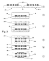
- FIG. 2 schematizes the main operations of the first embodiment of the invention.
- two identical subassemblies 20a-20b are formed, each formed of a substrate 21 and a metal current collector.
- grid-shaped 22 deposited on the substrate.
- the collector has, in section, a mushroom or harpoon profile and, typically, a thickness of 5 to 10 microns.
- the face of the substrate which receives the collector is such that it can be detached by mechanical action, chemical or thermal.
- Each collector 22 is advantageously made, in situ, by galvanic gold deposition using a mask formed on the substrate, according to the method described in detail in the document EP 04 405063.1 already mentioned.
- the collectors 22 could also be made separately and then transferred to the substrates and fixed to them by gluing.
- this layer is spread by a technique known as "spin coating" and has a thickness of 10 to 20 microns.
- the resulting subassemblies 24a-24b are respectively fixed on the working trays of a machine, called "flip chip bonding", not shown. drawing and well known to those skilled in the art, the two half-membranes 23 facing each other.
- the separation is done by a simple mechanical action. If the collectors have been reported and fixed by gluing, the separation is done by a chemical and / or thermal action.
- the assembly comprising a solidified membrane 26 and the two collectors 22 incorporated, face to face, in the membrane.
- the assembly has a thickness of 20 to 40 ⁇ m.
- the two faces of the assembly 25 are, in line with the collectors 22, covered with a catalyst layer 27 essentially comprising catalyst elements proper, such as platinum and ruthenium, and electrical and ionic conductive elements, such as carbon and the same material as that constituting the membrane 26.
- catalyst elements proper such as platinum and ruthenium
- electrical and ionic conductive elements such as carbon and the same material as that constituting the membrane 26.
- a polymerizable ionic membrane 28, of the same type as the half-membranes 23, but of double thickness is deposited, in the liquid or pasty state, on the assembly 20a to form the subassembly 29.
- the assemblies 20b and 29 are respectively fixed to the work trays of a "flip chip bonding" machine, the membrane 28 facing the collector 22 of the set 20b.
- the alignment and flatness of the assemblies 20b and 29 having been adjusted, they are applied against each other by the machine, under pressure, to a temperature and for a duration such that the collector 22 of the assembly 20b is incrusted in the membrane which solidifies by polymerization.
- the structure obtained suffers from the fact that the thin membrane 26 is liable to deform under the action of moisture, which poses a problem when it comes to handling the assembly for the incorporate into a fuel cell.
- the above problem is solved by inserting the assembly 25 between two rigid frames 30, advantageously made of PVC and fixed to one another by means of spikes. 31 It will be noted that these frames also serve as supports for electrical contacts 32 connecting the two collectors 22 to the outside.
- This "packaging" of the assembly like a slide, stabilizes the shape of the membrane and facilitates its handling.
- FIG. 5 shows that the simple frames 30 of FIG. 4 are replaced by rigid covers 33, advantageously made of PVC and also fixed to each other by spikes (not shown). . These covers are provided with connection tips 34 which also ensure the stiffening of the assembly but also provide, on either side of the catalysts 27, spaces 35 for the necessary reagents. Seals 36 seal these spaces.
- the structure of Figure 5 thus constitutes a complete fuel cell.
Landscapes
- Life Sciences & Earth Sciences (AREA)
- Engineering & Computer Science (AREA)
- Manufacturing & Machinery (AREA)
- Sustainable Development (AREA)
- Sustainable Energy (AREA)
- Chemical & Material Sciences (AREA)
- Chemical Kinetics & Catalysis (AREA)
- Electrochemistry (AREA)
- General Chemical & Material Sciences (AREA)
- Fuel Cell (AREA)
Priority Applications (5)
| Application Number | Priority Date | Filing Date | Title |
|---|---|---|---|
| DE602004018123T DE602004018123D1 (de) | 2004-07-06 | 2004-07-06 | Miniatur-Brennstoffzellekern |
| EP04405424A EP1615285B1 (de) | 2004-07-06 | 2004-07-06 | Miniatur-Brennstoffzellekern |
| PCT/EP2005/052934 WO2006003108A2 (fr) | 2004-07-06 | 2005-06-23 | Coeur de pile a combustible miniature |
| US11/630,098 US7846611B2 (en) | 2004-07-06 | 2005-06-23 | Miniature fuel cell core |
| US12/908,918 US20110053047A1 (en) | 2004-07-06 | 2010-10-21 | Miniature fuel cell core |
Applications Claiming Priority (1)
| Application Number | Priority Date | Filing Date | Title |
|---|---|---|---|
| EP04405424A EP1615285B1 (de) | 2004-07-06 | 2004-07-06 | Miniatur-Brennstoffzellekern |
Publications (2)
| Publication Number | Publication Date |
|---|---|
| EP1615285A1 true EP1615285A1 (de) | 2006-01-11 |
| EP1615285B1 EP1615285B1 (de) | 2008-12-03 |
Family
ID=34932184
Family Applications (1)
| Application Number | Title | Priority Date | Filing Date |
|---|---|---|---|
| EP04405424A Expired - Lifetime EP1615285B1 (de) | 2004-07-06 | 2004-07-06 | Miniatur-Brennstoffzellekern |
Country Status (4)
| Country | Link |
|---|---|
| US (2) | US7846611B2 (de) |
| EP (1) | EP1615285B1 (de) |
| DE (1) | DE602004018123D1 (de) |
| WO (1) | WO2006003108A2 (de) |
Citations (4)
| Publication number | Priority date | Publication date | Assignee | Title |
|---|---|---|---|---|
| EP1258937A1 (de) * | 2001-05-17 | 2002-11-20 | STMicroelectronics S.r.l. | Mikro-Silizium-Brennstoffzelle, Verfahren zur Herstellung und autonome Halbleitervorrichtung mit Mikro-Brennstoffzelle |
| US20040058220A1 (en) * | 2002-09-20 | 2004-03-25 | Qin Liu | Fuel cell reactant and byproduct systems |
| US20040081878A1 (en) * | 2002-10-29 | 2004-04-29 | Peter Mardilovich | Fuel cell with embedded current collector |
| US20040115507A1 (en) * | 2002-12-05 | 2004-06-17 | Potter Curtis N | Monolithic fuel cell and method of manufacture |
Family Cites Families (5)
| Publication number | Priority date | Publication date | Assignee | Title |
|---|---|---|---|---|
| JPH05174878A (ja) * | 1991-12-20 | 1993-07-13 | Fujitsu Ltd | フリップチップ接合方法 |
| US5989741A (en) * | 1997-06-10 | 1999-11-23 | E.I. Du Pont De Nemours And Company | Electrochemical cell system with side-by-side arrangement of cells |
| FR2857162B1 (fr) | 2003-07-01 | 2014-04-11 | Commissariat Energie Atomique | Pile a combustible comportant des collecteurs de courant integres a l'empilement electrode-membrane-electrode. |
| US20050064291A1 (en) * | 2003-09-18 | 2005-03-24 | Matsushita Electric Industrial Co., Ltd. | Battery and non-aqueous electrolyte secondary battery using the same |
| ATE334484T1 (de) | 2004-02-02 | 2006-08-15 | Suisse Electronique Microtech | Verfahren zur herstellung eines stromkollektor- membran verbundes für brennstoffzellen |
-
2004
- 2004-07-06 EP EP04405424A patent/EP1615285B1/de not_active Expired - Lifetime
- 2004-07-06 DE DE602004018123T patent/DE602004018123D1/de not_active Expired - Fee Related
-
2005
- 2005-06-23 US US11/630,098 patent/US7846611B2/en not_active Expired - Fee Related
- 2005-06-23 WO PCT/EP2005/052934 patent/WO2006003108A2/fr not_active Ceased
-
2010
- 2010-10-21 US US12/908,918 patent/US20110053047A1/en not_active Abandoned
Patent Citations (4)
| Publication number | Priority date | Publication date | Assignee | Title |
|---|---|---|---|---|
| EP1258937A1 (de) * | 2001-05-17 | 2002-11-20 | STMicroelectronics S.r.l. | Mikro-Silizium-Brennstoffzelle, Verfahren zur Herstellung und autonome Halbleitervorrichtung mit Mikro-Brennstoffzelle |
| US20040058220A1 (en) * | 2002-09-20 | 2004-03-25 | Qin Liu | Fuel cell reactant and byproduct systems |
| US20040081878A1 (en) * | 2002-10-29 | 2004-04-29 | Peter Mardilovich | Fuel cell with embedded current collector |
| US20040115507A1 (en) * | 2002-12-05 | 2004-06-17 | Potter Curtis N | Monolithic fuel cell and method of manufacture |
Also Published As
| Publication number | Publication date |
|---|---|
| DE602004018123D1 (de) | 2009-01-15 |
| EP1615285B1 (de) | 2008-12-03 |
| US7846611B2 (en) | 2010-12-07 |
| WO2006003108A2 (fr) | 2006-01-12 |
| WO2006003108A3 (fr) | 2006-07-06 |
| US20080032175A1 (en) | 2008-02-07 |
| US20110053047A1 (en) | 2011-03-03 |
Similar Documents
| Publication | Publication Date | Title |
|---|---|---|
| EP0298800B1 (de) | Verfahren zur Herstellung einer Mehrschichtstruktur zur Herstellung von als Dünnschicht ausgebildeten elektrochemischen Generatoren mit einer Lithiumdünnschicht und einem Feststoff-Polymerelektrolyten | |
| EP2061114B1 (de) | Brennstoffzelle, bestehend aus mehreren Elementarzellen, die durch Serienschaltung mit den Stromkollektoren miteinander verbunden sind | |
| EP2870654B1 (de) | Verfahren zur montage und verkapselung von lithiummikrobatterien und mit diesem verfahren hergestellte mikrobatterien | |
| EP3118920B1 (de) | Selbsttragende dünnschicht-batterie, und herstellungsverfahren einer solchen batterie | |
| FR3146761A1 (fr) | Procede de fabrication de batteries, et batterie obtenue par ce procede | |
| EP1915797B1 (de) | Polymerverbundmembran mit ionen-/elektronenleitfähigkeit, herstellungsverfahren dafür und kern einer planaren brennstoffzelle mit dieser membran | |
| FR2880199A1 (fr) | Procede de fabrication d'un ensemble pour pile a combustible | |
| EP2867942B1 (de) | Lithiumionenbatterie mit einer kathode von variabler durchlässigkeit und entsprechendes verfahren | |
| EP2288832A1 (de) | Anordnung mit einer dichtung, die zwischen zwei komponenten mit unterschiedlichen wärmeausdehnungskoeffizienten geschaltet ist, zugehöriges pedal, anwendung zum abdichten von höchstspannungs-elektrolyseuren und feststoff-brennstoffzellen | |
| EP1615285B1 (de) | Miniatur-Brennstoffzellekern | |
| EP2301101B1 (de) | Brennstoffzelle mit einem zu dem trägersubstrat senkrechten membran-/elektrodenstapel und herstellungsprozess | |
| WO2008083836A1 (fr) | Plaque bipolaire pour pile a combustible a membrane polymere | |
| EP2867947B1 (de) | Verfahren zur herstellung einer elektroden-/protonenaustauschmembrananordnung | |
| WO2002061181A2 (fr) | Electrode de grandes dimensions | |
| EP1950825A1 (de) | Flexible Metall-Graphit-Verteilerplatte für eine Brennstoffzelle | |
| WO2007068810A1 (fr) | Pile a combustible avec collecteurs de courant integres a l'electrolyte solide et procede de fabrication d'une telle pile a combustible. | |
| FR3077681A1 (fr) | Batterie en couches minces | |
| EP1562243B1 (de) | Verfahren zur Herstellung eines Stromkollektor-Membran Verbundes für Brennstoffzellen | |
| EP4016677A1 (de) | Verfahren zur herstellung einer ablaufführung für elektrochemischen reaktor | |
| EP4203116B1 (de) | Verfahren zur herstellung eines strömungsleiters für einen elektrochemischen reaktor | |
| CA3062030A1 (fr) | Procede d'assemblage pour pile a combustible | |
| EP4191714A1 (de) | Strömungsführung für elektrochemischen reaktor und verfahren zu ihrer herstellung | |
| FR3142041A1 (fr) | Procede de fabrication de batteries a ions de lithium, notamment a forte puissance, et batterie obtenue par ce procede | |
| EP4203117A1 (de) | Dichtung für elektrochemischen reaktor und herstellungsverfahren dafür | |
| FR2616593A1 (fr) | Procede de fabrication de groupes de plaques ou grilles electrodes negatives pour des accumulateurs au plomb, et groupes de plaques ou grilles realises selon ce procede |
Legal Events
| Date | Code | Title | Description |
|---|---|---|---|
| PUAI | Public reference made under article 153(3) epc to a published international application that has entered the european phase |
Free format text: ORIGINAL CODE: 0009012 |
|
| AK | Designated contracting states |
Kind code of ref document: A1 Designated state(s): AT BE BG CH CY CZ DE DK EE ES FI FR GB GR HU IE IT LI LU MC NL PL PT RO SE SI SK TR |
|
| AX | Request for extension of the european patent |
Extension state: AL HR LT LV MK |
|
| 17P | Request for examination filed |
Effective date: 20060518 |
|
| AKX | Designation fees paid |
Designated state(s): CH DE FR GB LI |
|
| RBV | Designated contracting states (corrected) |
Designated state(s): CH DE FR GB LI |
|
| GRAP | Despatch of communication of intention to grant a patent |
Free format text: ORIGINAL CODE: EPIDOSNIGR1 |
|
| GRAS | Grant fee paid |
Free format text: ORIGINAL CODE: EPIDOSNIGR3 |
|
| GRAA | (expected) grant |
Free format text: ORIGINAL CODE: 0009210 |
|
| AK | Designated contracting states |
Kind code of ref document: B1 Designated state(s): CH DE FR GB LI |
|
| REG | Reference to a national code |
Ref country code: GB Ref legal event code: FG4D Free format text: NOT ENGLISH |
|
| REG | Reference to a national code |
Ref country code: CH Ref legal event code: EP |
|
| REF | Corresponds to: |
Ref document number: 602004018123 Country of ref document: DE Date of ref document: 20090115 Kind code of ref document: P |
|
| REG | Reference to a national code |
Ref country code: CH Ref legal event code: NV Representative=s name: GLN S.A. |
|
| PLBE | No opposition filed within time limit |
Free format text: ORIGINAL CODE: 0009261 |
|
| STAA | Information on the status of an ep patent application or granted ep patent |
Free format text: STATUS: NO OPPOSITION FILED WITHIN TIME LIMIT |
|
| PGFP | Annual fee paid to national office [announced via postgrant information from national office to epo] |
Ref country code: FR Payment date: 20090717 Year of fee payment: 6 |
|
| 26N | No opposition filed |
Effective date: 20090904 |
|
| PGFP | Annual fee paid to national office [announced via postgrant information from national office to epo] |
Ref country code: DE Payment date: 20090729 Year of fee payment: 6 Ref country code: CH Payment date: 20090728 Year of fee payment: 6 |
|
| GBPC | Gb: european patent ceased through non-payment of renewal fee |
Effective date: 20090706 |
|
| PG25 | Lapsed in a contracting state [announced via postgrant information from national office to epo] |
Ref country code: GB Free format text: LAPSE BECAUSE OF NON-PAYMENT OF DUE FEES Effective date: 20090706 |
|
| REG | Reference to a national code |
Ref country code: CH Ref legal event code: PL |
|
| REG | Reference to a national code |
Ref country code: FR Ref legal event code: ST Effective date: 20110331 |
|
| PG25 | Lapsed in a contracting state [announced via postgrant information from national office to epo] |
Ref country code: DE Free format text: LAPSE BECAUSE OF NON-PAYMENT OF DUE FEES Effective date: 20110201 Ref country code: LI Free format text: LAPSE BECAUSE OF NON-PAYMENT OF DUE FEES Effective date: 20100731 Ref country code: CH Free format text: LAPSE BECAUSE OF NON-PAYMENT OF DUE FEES Effective date: 20100731 |
|
| REG | Reference to a national code |
Ref country code: DE Ref legal event code: R119 Ref document number: 602004018123 Country of ref document: DE Effective date: 20110201 |
|
| PG25 | Lapsed in a contracting state [announced via postgrant information from national office to epo] |
Ref country code: FR Free format text: LAPSE BECAUSE OF NON-PAYMENT OF DUE FEES Effective date: 20100802 |