EP1615330A1 - Lastwinkelsteuerung für einen Synchronmotor, insbesondere für Lüfter - Google Patents
Lastwinkelsteuerung für einen Synchronmotor, insbesondere für Lüfter Download PDFInfo
- Publication number
- EP1615330A1 EP1615330A1 EP04425483A EP04425483A EP1615330A1 EP 1615330 A1 EP1615330 A1 EP 1615330A1 EP 04425483 A EP04425483 A EP 04425483A EP 04425483 A EP04425483 A EP 04425483A EP 1615330 A1 EP1615330 A1 EP 1615330A1
- Authority
- EP
- European Patent Office
- Prior art keywords
- electric motor
- load angle
- flow rate
- fan
- vwindings
- Prior art date
- Legal status (The legal status is an assumption and is not a legal conclusion. Google has not performed a legal analysis and makes no representation as to the accuracy of the status listed.)
- Granted
Links
- 230000001360 synchronised effect Effects 0.000 title claims abstract description 26
- 238000000034 method Methods 0.000 claims abstract description 35
- 238000004804 winding Methods 0.000 claims abstract description 15
- 239000012530 fluid Substances 0.000 claims abstract description 7
- 239000000779 smoke Substances 0.000 description 11
- 239000007789 gas Substances 0.000 description 9
- 238000012384 transportation and delivery Methods 0.000 description 8
- 230000001052 transient effect Effects 0.000 description 5
- 238000010586 diagram Methods 0.000 description 3
- 238000012423 maintenance Methods 0.000 description 3
- CURLTUGMZLYLDI-UHFFFAOYSA-N Carbon dioxide Chemical compound O=C=O CURLTUGMZLYLDI-UHFFFAOYSA-N 0.000 description 2
- 238000004364 calculation method Methods 0.000 description 2
- 238000002485 combustion reaction Methods 0.000 description 2
- 230000005672 electromagnetic field Effects 0.000 description 2
- 230000001105 regulatory effect Effects 0.000 description 2
- UGFAIRIUMAVXCW-UHFFFAOYSA-N Carbon monoxide Chemical compound [O+]#[C-] UGFAIRIUMAVXCW-UHFFFAOYSA-N 0.000 description 1
- 238000010521 absorption reaction Methods 0.000 description 1
- 230000008033 biological extinction Effects 0.000 description 1
- 239000003990 capacitor Substances 0.000 description 1
- 229910002092 carbon dioxide Inorganic materials 0.000 description 1
- 239000001569 carbon dioxide Substances 0.000 description 1
- 229910002091 carbon monoxide Inorganic materials 0.000 description 1
- 230000002860 competitive effect Effects 0.000 description 1
- 230000000295 complement effect Effects 0.000 description 1
- 238000006073 displacement reaction Methods 0.000 description 1
- 230000000694 effects Effects 0.000 description 1
- 238000000605 extraction Methods 0.000 description 1
- 230000004907 flux Effects 0.000 description 1
- 238000010438 heat treatment Methods 0.000 description 1
- 230000010355 oscillation Effects 0.000 description 1
- 231100000331 toxic Toxicity 0.000 description 1
- 230000002588 toxic effect Effects 0.000 description 1
- XLYOFNOQVPJJNP-UHFFFAOYSA-N water Substances O XLYOFNOQVPJJNP-UHFFFAOYSA-N 0.000 description 1
Images


Classifications
-
- H—ELECTRICITY
- H02—GENERATION; CONVERSION OR DISTRIBUTION OF ELECTRIC POWER
- H02P—CONTROL OR REGULATION OF ELECTRIC MOTORS, ELECTRIC GENERATORS OR DYNAMO-ELECTRIC CONVERTERS; CONTROLLING TRANSFORMERS, REACTORS OR CHOKE COILS
- H02P6/00—Arrangements for controlling synchronous motors or other dynamo-electric motors using electronic commutation dependent on the rotor position; Electronic commutators therefor
- H02P6/08—Arrangements for controlling the speed or torque of a single motor
-
- F—MECHANICAL ENGINEERING; LIGHTING; HEATING; WEAPONS; BLASTING
- F04—POSITIVE - DISPLACEMENT MACHINES FOR LIQUIDS; PUMPS FOR LIQUIDS OR ELASTIC FLUIDS
- F04D—NON-POSITIVE-DISPLACEMENT PUMPS
- F04D27/00—Control, e.g. regulation, of pumps, pumping installations or pumping systems specially adapted for elastic fluids
- F04D27/001—Testing thereof; Determination or simulation of flow characteristics; Stall or surge detection, e.g. condition monitoring
-
- F—MECHANICAL ENGINEERING; LIGHTING; HEATING; WEAPONS; BLASTING
- F04—POSITIVE - DISPLACEMENT MACHINES FOR LIQUIDS; PUMPS FOR LIQUIDS OR ELASTIC FLUIDS
- F04D—NON-POSITIVE-DISPLACEMENT PUMPS
- F04D27/00—Control, e.g. regulation, of pumps, pumping installations or pumping systems specially adapted for elastic fluids
- F04D27/004—Control, e.g. regulation, of pumps, pumping installations or pumping systems specially adapted for elastic fluids by varying driving speed
-
- H—ELECTRICITY
- H02—GENERATION; CONVERSION OR DISTRIBUTION OF ELECTRIC POWER
- H02P—CONTROL OR REGULATION OF ELECTRIC MOTORS, ELECTRIC GENERATORS OR DYNAMO-ELECTRIC CONVERTERS; CONTROLLING TRANSFORMERS, REACTORS OR CHOKE COILS
- H02P25/00—Arrangements or methods for the control of AC motors characterised by the kind of AC motor or by structural details
- H02P25/02—Arrangements or methods for the control of AC motors characterised by the kind of AC motor or by structural details characterised by the kind of motor
- H02P25/022—Synchronous motors
- H02P25/03—Synchronous motors with brushless excitation
-
- Y—GENERAL TAGGING OF NEW TECHNOLOGICAL DEVELOPMENTS; GENERAL TAGGING OF CROSS-SECTIONAL TECHNOLOGIES SPANNING OVER SEVERAL SECTIONS OF THE IPC; TECHNICAL SUBJECTS COVERED BY FORMER USPC CROSS-REFERENCE ART COLLECTIONS [XRACs] AND DIGESTS
- Y02—TECHNOLOGIES OR APPLICATIONS FOR MITIGATION OR ADAPTATION AGAINST CLIMATE CHANGE
- Y02B—CLIMATE CHANGE MITIGATION TECHNOLOGIES RELATED TO BUILDINGS, e.g. HOUSING, HOUSE APPLIANCES OR RELATED END-USER APPLICATIONS
- Y02B30/00—Energy efficient heating, ventilation or air conditioning [HVAC]
- Y02B30/70—Efficient control or regulation technologies, e.g. for control of refrigerant flow, motor or heating
Definitions
- the present invention relates, in its more general aspect, to a synchronous electric motor particularly, but not exclusively, used in smoke suction fans mounted in wall boilers.
- the invention relates to a driving method of a synchronous electric motor comprising a rotor equipped with a permanent magnet, which is rotation-operated by the electromagnetic field generated by a stator being equipped with pole pieces and the relevant windings.
- wall boilers are equipped with smoke extraction fans, commonly called exhaust fans, generally operated by asynchronous electric motors.
- Wall boilers generally comprise, besides a burner, a driving electronic box allowing the burner to be turned on and off, eventually by means of a timer, as well as the increase or decrease of the plant circulation water temperature to be regulated.
- Smokes produced by the burner have different physical features according to the boiler operation speed and thus, in order to optimise the boiler operation, the fan should adjust the smoke suction to this operation speed.
- an initial thermal-transient step occurs, after which a steady-state step begins, which can be defined as a fixed-displacement state.
- a steady-state step begins, which can be defined as a fixed-displacement state.
- the smokes being produced have a higher density and the fan should thus change the motor operating conditions by sucking more in order to extract smokes and allow the boiler to operate in the best way.
- This lock undergoes, for a good operation, a constant and accurate maintenance without which a burner shutdown and/or an extremely dangerous toxic smoke saturation in the boiler room and eventually in adjacent rooms is threatened.
- Too sharp changes of the load flow rate can also cause a temporary motor shutdown, which would require a sudden manual or automatic intervention for a new starting.
- the electric motor always operates at a speed approaching the highest efficiency speed, defined by an operation point corresponding to the lowest power absorbed by the line, also resulting in energy saving for the user.
- these flow meters are devices being positioned in correspondence with the fan deliveries and, by exploiting different principles, determining the gas volume flowing through a given section in a predetermined time, in particular a differential manostat can be for example provided, positioned between the fan suction and delivery.
- the technical problem underlying the present invention is to provide a driving method of a synchronous electric motor, particularly for the fan operation, allowing all the drawbacks mentioned with reference to the prior art to be overcome in a simple and cheap way.
- this driving method must be capable to minimise the power being absorbed at all motor operation speeds, solving possible critical load change situations which could stall the synchronous electric motor.
- the solution idea underlying the present invention is to provide a driving method allowing the mass flow rate of a synchronous electric motor to be kept constant when the load changes.
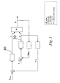
- FIG. 1 a block diagram of the algorithm processing principle is shown, whereon the driving method realised according to the present invention is based.
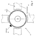
- This diagram is globally indicated with 1 and it is suitable to drive a synchronous electric motor 12, as shown in figures 3 and 4, in particular to operate a fan 8.
- the fan 8 has a body 9 for housing an impeller 10 coupled to an end of the motor 12 rotor, allowing the impeller 10 to rotate and thus smokes to be sucked by a suction duct in order to push them towards a delivery duct 11.
- the synchronous motor 12 comprises a rotor 14, equipped with a permanent magnet which is rotation-operated by the electromagnetic field generated by a stator 16, equipped with pole pieces 18 and the relevant windings.
- the motor 12 comprises a magnetic flux sensor 20 of the rotor 14, for example a Hall sensor, particularly an analogue sensor, positioned on the stator 16 close to the rotor 14.
- the sensor 20 outputs a signal defining the momentary position of the rotor 14.
- the signal of the sensor 20 is a signal being phased with the counter electromotive force E in the absence of a constant.
- the phase angle between the counter electromotive force E and the network voltage V provides the load angle ⁇ of the motor 12.
- the mass flow rate depends on the gas density, on the dynamic pressure thereof in convection and/or forced-circulation in the body 9 of the fan 8 and on the gas temperature.
- a change of the features of the gas flowing through the body 9 of the fan 8 involves a change of the mass flow rate and thus of the load angle ⁇ of the motor 12.
- the synchronous motor 12 has for each load, and thus for each load angle ⁇ , an ideal operation point which will be called “optimum point", wherein the motor 12 absorbs the lowest quantity of current and it conveys the highest power to the load.
- This situation can be represented by cusp curves having a well defined minimum being already identified by the prior art.
- a possible solution provides to rectify an alternate voltage provided by the network by means of a diode bridge followed by a capacitor stage, allowing the rectified voltage to be levelled.
- the so-obtained voltage is conveniently modulated by means of some switches (IGBT or power MOS 7), conveniently controlled according to a PWM modulation technique, which allows a voltage to be provided to the windings of the pole pieces 18, whose frequency and fundamental sinusoid amplitude can be varied.
- the voltage of half the bridge would be V BUS/2 if not being connected to the load.
- the voltage at the bridge centre varies around the value V BUS/2 according to a sinusoid law with a ripple whose oscillation frequency is equal to the PWM frequency.
- the operating conditions of the synchronous motor 12 are kept close to the "optimum point" by means of a first and second regulation loop 30, 40, schematically indicated in figure 1, both feedback operating.
- the first loop 30, also defined as inner or faster loop, regulates the supply voltage provided to the windings of the pole pieces 18 and indicated with Vwindings, according to the load angle ⁇ car deviation from the optimum angle ⁇ ott .
- the optimum angle ⁇ ott is drawn from experimental measures, known in the prior art, and it is indicated in convenient tables. By operating according to the "optimum angle", the motor absorbs the lowest current according to the different loads or load powers.
- the load angle ⁇ car of the synchronous motor 12 is steadily provided, based on the signal processing of the Hall sensor 20.
- FIG. 5 schematically shows a power circuit 24 with an active element bridge 26 which can be used to this purpose.
- the second regulation loop 40 also defined as external slower loop, regulates the frequency f of the synchronous motor 12 according to the voltage Vwindings provided to the windings L1.L2 of the pole pieces 18, based on the first loop 30.
- this second loop 40 allows the synchronous motor 12 to operate in steady conditions.
- the synchronous motor has for each load power a lower stability limit given by a lowest voltage provided to the motor according to a predetermined operating frequency.
- the voltage Vwindings provided to the synchronous motor 12 is related to the fan mass flow rate P massica and proportional to this mass flow rate.
- the reference mass flow rate P target is, in the case of the fan 8, the one ensuring an effective and safe combustion, i.e. obtained through a convenient concentration of burnt gases carbon monoxide, carbon dioxide and nitric oxides.
- the voltage Vwindings is regulated according to the first loop 30 so that the load angle ⁇ car follows the optimum load angle ⁇ ott .
- the second loop 40 will thus allow the frequency f of the synchronous motor 12 to be changed in order to keep the P target and avoid any instability of the motor 12.
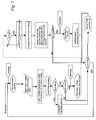
- the method according to the invention thus provides to compare the real angle ⁇ car with the optimum load angle ⁇ ott by changing Vwindings and the operating frequency f up to reach the optimum load value ⁇ ott .
- control method provides to keep the mass flow rate constant by changing the motor operating conditions by means of two feedback cycles; a first inner faster cycle 30 allowing the winding voltage to be changed and a second outer cycle 40 allowing the frequency f to be changed.
- the frequency f change takes more time than the voltage Vwindings change and particularly when the winding voltage Vwindings is steady. Therefore the synchronous motor is avoided to operate under almost unsteady conditions wherein the motor could not succeed in following the supply voltage, risking a sudden interruption.
- the above-described method allows to avoid, in the case of the fan, hood, smokes, during the initial burner transient, the load angle change from being considered as a change of the aeraulic load.
- the temperature increases according to a given transient, by applying a control system as indicated in the European patent application no. 03425571.1 of the same Applicant this temperature change can be conveniently determined.
- the present method can have different alternative embodiments among which the case of the digital Hall sensor can be considered.
- mass flow rate P mass being calculated could be provided as a signal for a convenient boiler control electronic box.
- control method allows any device for measuring the flow rate to be eliminated, as well as the lock positioned in the fan delivery and the differential manostat positioned between the fan suction and delivery.
- this method allows the smoke mass flow rate to be calculated and kept constant in time and an output signal being proportional to the mass flow rate to be provided, or simply an alarm signal when the mass flow rate is not sufficient.
- the boiler control electronic box will provide the extinction of the pilot flame in case of alarm or it will process a flow rate signal by modulating the gas pressure at the burner nozzles.
- a further advantage of the suggested control method is the complete removal of the smoke flow rate regulation lock positioned downstream the fan, thus improving the fan operating conditions with respect to the emitted smokes and considerably reducing maintenance operations.
- a further advantage of the suggested control method according to the present solution is the constant control of the smoke mass flow rate, allowing the combustion efficiency to be improved in the fan operation areas outside the target point, as for example during the boiler starting transient.
- Another advantage of the suggested control method is to allow the smoke mass flow rate to be kept constant in time by changing the motor operating conditions.
Landscapes
- Engineering & Computer Science (AREA)
- Mechanical Engineering (AREA)
- General Engineering & Computer Science (AREA)
- Power Engineering (AREA)
- Control Of Positive-Displacement Air Blowers (AREA)
- Control Of Ac Motors In General (AREA)
- Control Of Motors That Do Not Use Commutators (AREA)
- Control Of Multiple Motors (AREA)
- Structures Of Non-Positive Displacement Pumps (AREA)
Priority Applications (6)
| Application Number | Priority Date | Filing Date | Title |
|---|---|---|---|
| ES04425483T ES2343408T3 (es) | 2004-06-30 | 2004-06-30 | Procedimiento para controlar el angulo de carga de un motor electrico sincrono, en particular para ventiladores. |
| EP04425483A EP1615330B1 (de) | 2004-06-30 | 2004-06-30 | Lastwinkelsteuerung für einen Synchronmotor, insbesondere für Lüfter |
| DE602004026165T DE602004026165D1 (de) | 2004-06-30 | 2004-06-30 | Lastwinkelsteuerung für einen Synchronmotor, insbesondere für Lüfter |
| AT04425483T ATE462220T1 (de) | 2004-06-30 | 2004-06-30 | Lastwinkelsteuerung für einen synchronmotor, insbesondere für lüfter |
| KR1020050056984A KR101074671B1 (ko) | 2004-06-30 | 2005-06-29 | 동기식 전기 모터 구동 방법 |
| US11/172,374 US7262576B2 (en) | 2004-06-30 | 2005-06-30 | Method for driving a synchronous electric motor in particular for fans |
Applications Claiming Priority (1)
| Application Number | Priority Date | Filing Date | Title |
|---|---|---|---|
| EP04425483A EP1615330B1 (de) | 2004-06-30 | 2004-06-30 | Lastwinkelsteuerung für einen Synchronmotor, insbesondere für Lüfter |
Publications (2)
| Publication Number | Publication Date |
|---|---|
| EP1615330A1 true EP1615330A1 (de) | 2006-01-11 |
| EP1615330B1 EP1615330B1 (de) | 2010-03-24 |
Family
ID=34932601
Family Applications (1)
| Application Number | Title | Priority Date | Filing Date |
|---|---|---|---|
| EP04425483A Expired - Lifetime EP1615330B1 (de) | 2004-06-30 | 2004-06-30 | Lastwinkelsteuerung für einen Synchronmotor, insbesondere für Lüfter |
Country Status (6)
| Country | Link |
|---|---|
| US (1) | US7262576B2 (de) |
| EP (1) | EP1615330B1 (de) |
| KR (1) | KR101074671B1 (de) |
| AT (1) | ATE462220T1 (de) |
| DE (1) | DE602004026165D1 (de) |
| ES (1) | ES2343408T3 (de) |
Cited By (2)
| Publication number | Priority date | Publication date | Assignee | Title |
|---|---|---|---|---|
| WO2013164565A3 (en) * | 2012-04-30 | 2014-01-30 | Isentropic Ltd | Improvements relating to the transmission of energy |
| ITMO20130093A1 (it) * | 2013-04-12 | 2014-10-13 | Irisman Mh Equipment Corp | Metodo per la regolazione del rendimento di una macchina sincrona |
Families Citing this family (1)
| Publication number | Priority date | Publication date | Assignee | Title |
|---|---|---|---|---|
| JP5904803B2 (ja) * | 2012-01-24 | 2016-04-20 | キヤノン株式会社 | 画像形成装置 |
Citations (4)
| Publication number | Priority date | Publication date | Assignee | Title |
|---|---|---|---|---|
| US4511834A (en) * | 1982-12-23 | 1985-04-16 | Borg-Warner Corporation | Control and stabilizing system for damperless synchronous motor |
| US4740738A (en) * | 1986-09-17 | 1988-04-26 | Westinghouse Electric Corp. | Reluctance motor control system and method |
| US5006774A (en) * | 1990-03-13 | 1991-04-09 | Sundstrand Corporation | Torque angle control system for controlling the torque angle of a permanent magnet synchronous motor |
| EP0702451A1 (de) * | 1994-09-19 | 1996-03-20 | Minimotor S.A. | Steuervorrichtung eines Synchronmotors |
Family Cites Families (9)
| Publication number | Priority date | Publication date | Assignee | Title |
|---|---|---|---|---|
| DE3920185A1 (de) | 1989-06-21 | 1991-01-10 | Oplaender Wilo Werk Gmbh | Kreiselpumpe oder luefter |
| KR940015423A (ko) * | 1992-12-29 | 1994-07-20 | 이헌조 | 가스보일러의 배기팬 회전속도 제어장치와 방법 |
| JPH0775376A (ja) * | 1993-06-14 | 1995-03-17 | Fujitsu General Ltd | ブラシレスモータの制御方法 |
| JP3368009B2 (ja) * | 1993-09-04 | 2003-01-20 | 東洋シヤッター株式会社 | シャッター駆動用の電動機の駆動制御装置 |
| JP3714814B2 (ja) * | 1999-01-28 | 2005-11-09 | シャープ株式会社 | インバータ洗濯機 |
| KR20010011524A (ko) * | 1999-07-28 | 2001-02-15 | 구자홍 | 에스알엠의 과전류 보호회로 |
| JP3786018B2 (ja) * | 2002-01-23 | 2006-06-14 | 富士電機機器制御株式会社 | 同期機の制御装置 |
| US6741049B2 (en) * | 2002-10-28 | 2004-05-25 | Melexis Nv Miroelectronics Integrated Systems | Low voltage start up circuit for brushless DC motors |
| DK1512949T3 (da) | 2003-09-04 | 2007-05-14 | Askoll Holding Srl | Fremgangsmåde og indretning til at bestemme den hydrauliske strömningsrate i en pumpe |
-
2004
- 2004-06-30 EP EP04425483A patent/EP1615330B1/de not_active Expired - Lifetime
- 2004-06-30 DE DE602004026165T patent/DE602004026165D1/de not_active Expired - Lifetime
- 2004-06-30 ES ES04425483T patent/ES2343408T3/es not_active Expired - Lifetime
- 2004-06-30 AT AT04425483T patent/ATE462220T1/de not_active IP Right Cessation
-
2005
- 2005-06-29 KR KR1020050056984A patent/KR101074671B1/ko not_active Expired - Fee Related
- 2005-06-30 US US11/172,374 patent/US7262576B2/en not_active Expired - Lifetime
Patent Citations (4)
| Publication number | Priority date | Publication date | Assignee | Title |
|---|---|---|---|---|
| US4511834A (en) * | 1982-12-23 | 1985-04-16 | Borg-Warner Corporation | Control and stabilizing system for damperless synchronous motor |
| US4740738A (en) * | 1986-09-17 | 1988-04-26 | Westinghouse Electric Corp. | Reluctance motor control system and method |
| US5006774A (en) * | 1990-03-13 | 1991-04-09 | Sundstrand Corporation | Torque angle control system for controlling the torque angle of a permanent magnet synchronous motor |
| EP0702451A1 (de) * | 1994-09-19 | 1996-03-20 | Minimotor S.A. | Steuervorrichtung eines Synchronmotors |
Cited By (6)
| Publication number | Priority date | Publication date | Assignee | Title |
|---|---|---|---|---|
| WO2013164565A3 (en) * | 2012-04-30 | 2014-01-30 | Isentropic Ltd | Improvements relating to the transmission of energy |
| CN104380592A (zh) * | 2012-04-30 | 2015-02-25 | 等熵有限公司 | 有关能量传输的改进 |
| US9425719B2 (en) | 2012-04-30 | 2016-08-23 | Energy Technologies Institute Llp | Transmission of energy |
| ITMO20130093A1 (it) * | 2013-04-12 | 2014-10-13 | Irisman Mh Equipment Corp | Metodo per la regolazione del rendimento di una macchina sincrona |
| CN104104284A (zh) * | 2013-04-12 | 2014-10-15 | 瑷瑞盟通商股份有限公司 | 调校控制交流同步电机效率的方法 |
| EP2790314A3 (de) * | 2013-04-12 | 2015-01-28 | Irisman MH Equipment Corp. | Verfahren zur Anpassung der Effizienz einer Synchronmaschine |
Also Published As
| Publication number | Publication date |
|---|---|
| ES2343408T3 (es) | 2010-07-30 |
| KR20060048694A (ko) | 2006-05-18 |
| EP1615330B1 (de) | 2010-03-24 |
| US7262576B2 (en) | 2007-08-28 |
| US20060033465A1 (en) | 2006-02-16 |
| DE602004026165D1 (de) | 2010-05-06 |
| KR101074671B1 (ko) | 2011-10-19 |
| ATE462220T1 (de) | 2010-04-15 |
Similar Documents
| Publication | Publication Date | Title |
|---|---|---|
| US6624606B2 (en) | Drive control circuit for three-phase brushless motor, motor-driven blower and electric vacuum cleaner | |
| US6545443B2 (en) | Pulse width modulation circuit controlling output current of an inverter circuit for motor-driven blower or electric vacuum cleaner | |
| KR100188898B1 (ko) | 전기청소기 및 그 제어방법 | |
| JP3738685B2 (ja) | インバータ装置および送風装置 | |
| JP6254276B2 (ja) | ファン・モータ風量の検出法 | |
| US20100076606A1 (en) | Method and apparatus for producing a constant air flow from a blower by sensing blower housing vacuum | |
| US9641115B2 (en) | Methods and systems for envelope and efficiency control in an electric motor | |
| WO2016029531A1 (zh) | 一种带滤网堵塞检测功能的电器设备 | |
| EP1417746A1 (de) | Drehzahlvariable steuerung für eine asynchronmaschine zur anwendung in der ventilation | |
| JP2017500470A5 (de) | ||
| US20260074631A1 (en) | System and method for advanced electronic starting switch assembly for split-phase induction motors for domestic dryers | |
| EP1615330B1 (de) | Lastwinkelsteuerung für einen Synchronmotor, insbesondere für Lüfter | |
| CN100408982C (zh) | 确定泵中的液力流率的方法和装置 | |
| CN104508969B (zh) | 装载有无刷dc电动机的送风装置 | |
| JP4888526B2 (ja) | 送風装置およびそれを搭載した電気機器 | |
| US6856115B2 (en) | Method of and apparatus for controlling the operation of an induction motor using a model of the induction motor | |
| JP6569089B2 (ja) | 天井扇風機 | |
| WO2016011617A1 (zh) | 一种送风设备的滤网堵塞检测方法及其应用的送风设备 | |
| JPH04210033A (ja) | 電気掃除機 | |
| JP2019203673A (ja) | 燃焼装置および給湯装置 | |
| RU2118892C1 (ru) | Система управления пылесосом | |
| KR20090042522A (ko) | 공기조화기의 팬용 전동기 제어방법 및 그 제어 장치 | |
| JP2007151347A (ja) | モータ制御装置及びそれを備えた送風装置 | |
| JP6182736B2 (ja) | 換気装置 | |
| KR970000252Y1 (ko) | 인버터 조리기의 스위칭소자 보호장치 |
Legal Events
| Date | Code | Title | Description |
|---|---|---|---|
| PUAI | Public reference made under article 153(3) epc to a published international application that has entered the european phase |
Free format text: ORIGINAL CODE: 0009012 |
|
| AK | Designated contracting states |
Kind code of ref document: A1 Designated state(s): AT BE BG CH CY CZ DE DK EE ES FI FR GB GR HU IE IT LI LU MC NL PL PT RO SE SI SK TR |
|
| AX | Request for extension of the european patent |
Extension state: AL HR LT LV MK |
|
| 17P | Request for examination filed |
Effective date: 20060707 |
|
| AKX | Designation fees paid |
Designated state(s): AT BE BG CH CY CZ DE DK EE ES FI FR GB GR HU IE IT LI LU MC NL PL PT RO SE SI SK TR |
|
| 17Q | First examination report despatched |
Effective date: 20060907 |
|
| GRAP | Despatch of communication of intention to grant a patent |
Free format text: ORIGINAL CODE: EPIDOSNIGR1 |
|
| RTI1 | Title (correction) |
Free format text: METHOD FOR CONTROLLING THE LOAD ANGLE OF A SYNCHRONOUS ELECTRIC MOTOR, IN PARTICULAR FOR FANS |
|
| GRAS | Grant fee paid |
Free format text: ORIGINAL CODE: EPIDOSNIGR3 |
|
| GRAA | (expected) grant |
Free format text: ORIGINAL CODE: 0009210 |
|
| AK | Designated contracting states |
Kind code of ref document: B1 Designated state(s): AT BE BG CH CY CZ DE DK EE ES FI FR GB GR HU IE IT LI LU MC NL PL PT RO SE SI SK TR |
|
| REG | Reference to a national code |
Ref country code: GB Ref legal event code: FG4D |
|
| REG | Reference to a national code |
Ref country code: CH Ref legal event code: EP |
|
| REG | Reference to a national code |
Ref country code: IE Ref legal event code: FG4D |
|
| REF | Corresponds to: |
Ref document number: 602004026165 Country of ref document: DE Date of ref document: 20100506 Kind code of ref document: P |
|
| REG | Reference to a national code |
Ref country code: NL Ref legal event code: VDEP Effective date: 20100324 |
|
| REG | Reference to a national code |
Ref country code: ES Ref legal event code: FG2A Ref document number: 2343408 Country of ref document: ES Kind code of ref document: T3 |
|
| PG25 | Lapsed in a contracting state [announced via postgrant information from national office to epo] |
Ref country code: SI Free format text: LAPSE BECAUSE OF FAILURE TO SUBMIT A TRANSLATION OF THE DESCRIPTION OR TO PAY THE FEE WITHIN THE PRESCRIBED TIME-LIMIT Effective date: 20100324 Ref country code: PL Free format text: LAPSE BECAUSE OF FAILURE TO SUBMIT A TRANSLATION OF THE DESCRIPTION OR TO PAY THE FEE WITHIN THE PRESCRIBED TIME-LIMIT Effective date: 20100324 Ref country code: FI Free format text: LAPSE BECAUSE OF FAILURE TO SUBMIT A TRANSLATION OF THE DESCRIPTION OR TO PAY THE FEE WITHIN THE PRESCRIBED TIME-LIMIT Effective date: 20100324 Ref country code: AT Free format text: LAPSE BECAUSE OF FAILURE TO SUBMIT A TRANSLATION OF THE DESCRIPTION OR TO PAY THE FEE WITHIN THE PRESCRIBED TIME-LIMIT Effective date: 20100324 |
|
| PG25 | Lapsed in a contracting state [announced via postgrant information from national office to epo] |
Ref country code: NL Free format text: LAPSE BECAUSE OF FAILURE TO SUBMIT A TRANSLATION OF THE DESCRIPTION OR TO PAY THE FEE WITHIN THE PRESCRIBED TIME-LIMIT Effective date: 20100324 Ref country code: GR Free format text: LAPSE BECAUSE OF FAILURE TO SUBMIT A TRANSLATION OF THE DESCRIPTION OR TO PAY THE FEE WITHIN THE PRESCRIBED TIME-LIMIT Effective date: 20100625 Ref country code: EE Free format text: LAPSE BECAUSE OF FAILURE TO SUBMIT A TRANSLATION OF THE DESCRIPTION OR TO PAY THE FEE WITHIN THE PRESCRIBED TIME-LIMIT Effective date: 20100324 Ref country code: BE Free format text: LAPSE BECAUSE OF FAILURE TO SUBMIT A TRANSLATION OF THE DESCRIPTION OR TO PAY THE FEE WITHIN THE PRESCRIBED TIME-LIMIT Effective date: 20100324 Ref country code: RO Free format text: LAPSE BECAUSE OF FAILURE TO SUBMIT A TRANSLATION OF THE DESCRIPTION OR TO PAY THE FEE WITHIN THE PRESCRIBED TIME-LIMIT Effective date: 20100324 Ref country code: SE Free format text: LAPSE BECAUSE OF FAILURE TO SUBMIT A TRANSLATION OF THE DESCRIPTION OR TO PAY THE FEE WITHIN THE PRESCRIBED TIME-LIMIT Effective date: 20100324 |
|
| PG25 | Lapsed in a contracting state [announced via postgrant information from national office to epo] |
Ref country code: CZ Free format text: LAPSE BECAUSE OF FAILURE TO SUBMIT A TRANSLATION OF THE DESCRIPTION OR TO PAY THE FEE WITHIN THE PRESCRIBED TIME-LIMIT Effective date: 20100324 Ref country code: BG Free format text: LAPSE BECAUSE OF FAILURE TO SUBMIT A TRANSLATION OF THE DESCRIPTION OR TO PAY THE FEE WITHIN THE PRESCRIBED TIME-LIMIT Effective date: 20100624 Ref country code: SK Free format text: LAPSE BECAUSE OF FAILURE TO SUBMIT A TRANSLATION OF THE DESCRIPTION OR TO PAY THE FEE WITHIN THE PRESCRIBED TIME-LIMIT Effective date: 20100324 |
|
| PLBE | No opposition filed within time limit |
Free format text: ORIGINAL CODE: 0009261 |
|
| STAA | Information on the status of an ep patent application or granted ep patent |
Free format text: STATUS: NO OPPOSITION FILED WITHIN TIME LIMIT |
|
| PG25 | Lapsed in a contracting state [announced via postgrant information from national office to epo] |
Ref country code: PT Free format text: LAPSE BECAUSE OF FAILURE TO SUBMIT A TRANSLATION OF THE DESCRIPTION OR TO PAY THE FEE WITHIN THE PRESCRIBED TIME-LIMIT Effective date: 20100726 Ref country code: MC Free format text: LAPSE BECAUSE OF NON-PAYMENT OF DUE FEES Effective date: 20100630 Ref country code: DK Free format text: LAPSE BECAUSE OF FAILURE TO SUBMIT A TRANSLATION OF THE DESCRIPTION OR TO PAY THE FEE WITHIN THE PRESCRIBED TIME-LIMIT Effective date: 20100324 |
|
| REG | Reference to a national code |
Ref country code: CH Ref legal event code: PL |
|
| 26N | No opposition filed |
Effective date: 20101228 |
|
| PG25 | Lapsed in a contracting state [announced via postgrant information from national office to epo] |
Ref country code: LI Free format text: LAPSE BECAUSE OF NON-PAYMENT OF DUE FEES Effective date: 20100630 Ref country code: IE Free format text: LAPSE BECAUSE OF NON-PAYMENT OF DUE FEES Effective date: 20100630 Ref country code: CH Free format text: LAPSE BECAUSE OF NON-PAYMENT OF DUE FEES Effective date: 20100630 |
|
| PG25 | Lapsed in a contracting state [announced via postgrant information from national office to epo] |
Ref country code: CY Free format text: LAPSE BECAUSE OF FAILURE TO SUBMIT A TRANSLATION OF THE DESCRIPTION OR TO PAY THE FEE WITHIN THE PRESCRIBED TIME-LIMIT Effective date: 20100324 |
|
| PG25 | Lapsed in a contracting state [announced via postgrant information from national office to epo] |
Ref country code: LU Free format text: LAPSE BECAUSE OF NON-PAYMENT OF DUE FEES Effective date: 20100630 Ref country code: HU Free format text: LAPSE BECAUSE OF FAILURE TO SUBMIT A TRANSLATION OF THE DESCRIPTION OR TO PAY THE FEE WITHIN THE PRESCRIBED TIME-LIMIT Effective date: 20100925 |
|
| REG | Reference to a national code |
Ref country code: FR Ref legal event code: PLFP Year of fee payment: 13 |
|
| REG | Reference to a national code |
Ref country code: ES Ref legal event code: PC2A Owner name: TACO ITALIA S.R.L. Effective date: 20160608 Ref country code: ES Ref legal event code: PC2A Owner name: TACO ITALIA S.R.L. Effective date: 20160628 |
|
| REG | Reference to a national code |
Ref country code: DE Ref legal event code: R082 Ref document number: 602004026165 Country of ref document: DE Representative=s name: PATENTANWAELTE BAUER VORBERG KAYSER PARTNERSCH, DE Ref country code: DE Ref legal event code: R081 Ref document number: 602004026165 Country of ref document: DE Owner name: TACO ITALIA S.R.L., IT Free format text: FORMER OWNER: ASKOLL HOLDING S.R.L., POVOLARO DI DUEVILLE, VICENZA, IT Ref country code: DE Ref legal event code: R082 Ref document number: 602004026165 Country of ref document: DE Representative=s name: MOSER GOETZE & PARTNER PATENTANWAELTE MBB, DE |
|
| REG | Reference to a national code |
Ref country code: GB Ref legal event code: 732E Free format text: REGISTERED BETWEEN 20160609 AND 20160615 |
|
| REG | Reference to a national code |
Ref country code: FR Ref legal event code: TP Owner name: TACO ITALIA S.R.L., IT Effective date: 20160615 |
|
| REG | Reference to a national code |
Ref country code: DE Ref legal event code: R082 Ref document number: 602004026165 Country of ref document: DE Representative=s name: MOSER GOETZE & PARTNER PATENTANWAELTE MBB, DE |
|
| REG | Reference to a national code |
Ref country code: FR Ref legal event code: PLFP Year of fee payment: 14 |
|
| REG | Reference to a national code |
Ref country code: FR Ref legal event code: PLFP Year of fee payment: 15 |
|
| PGFP | Annual fee paid to national office [announced via postgrant information from national office to epo] |
Ref country code: SE Payment date: 20190521 Year of fee payment: 16 |
|
| PGFP | Annual fee paid to national office [announced via postgrant information from national office to epo] |
Ref country code: ES Payment date: 20190701 Year of fee payment: 16 Ref country code: GB Payment date: 20190522 Year of fee payment: 16 |
|
| GBPC | Gb: european patent ceased through non-payment of renewal fee |
Effective date: 20200630 |
|
| PG25 | Lapsed in a contracting state [announced via postgrant information from national office to epo] |
Ref country code: GB Free format text: LAPSE BECAUSE OF NON-PAYMENT OF DUE FEES Effective date: 20200630 Ref country code: FR Free format text: LAPSE BECAUSE OF NON-PAYMENT OF DUE FEES Effective date: 20200630 |
|
| REG | Reference to a national code |
Ref country code: ES Ref legal event code: FD2A Effective date: 20211105 |
|
| PG25 | Lapsed in a contracting state [announced via postgrant information from national office to epo] |
Ref country code: ES Free format text: LAPSE BECAUSE OF NON-PAYMENT OF DUE FEES Effective date: 20200701 |
|
| PGFP | Annual fee paid to national office [announced via postgrant information from national office to epo] |
Ref country code: IT Payment date: 20230523 Year of fee payment: 20 Ref country code: DE Payment date: 20230523 Year of fee payment: 20 |
|
| PGFP | Annual fee paid to national office [announced via postgrant information from national office to epo] |
Ref country code: TR Payment date: 20230529 Year of fee payment: 20 |
|
| REG | Reference to a national code |
Ref country code: DE Ref legal event code: R071 Ref document number: 602004026165 Country of ref document: DE |