EP1615550B1 - Procede de surveillance du systeme nerveux - Google Patents
Procede de surveillance du systeme nerveux Download PDFInfo
- Publication number
- EP1615550B1 EP1615550B1 EP04727037A EP04727037A EP1615550B1 EP 1615550 B1 EP1615550 B1 EP 1615550B1 EP 04727037 A EP04727037 A EP 04727037A EP 04727037 A EP04727037 A EP 04727037A EP 1615550 B1 EP1615550 B1 EP 1615550B1
- Authority
- EP
- European Patent Office
- Prior art keywords
- stimulus
- nervous system
- measurements
- voltage measurements
- brain
- Prior art date
- Legal status (The legal status is an assumption and is not a legal conclusion. Google has not performed a legal analysis and makes no representation as to the accuracy of the status listed.)
- Expired - Lifetime
Links
Images


Classifications
-
- A—HUMAN NECESSITIES
- A61—MEDICAL OR VETERINARY SCIENCE; HYGIENE
- A61B—DIAGNOSIS; SURGERY; IDENTIFICATION
- A61B5/00—Measuring for diagnostic purposes; Identification of persons
- A61B5/05—Detecting, measuring or recording for diagnosis by means of electric currents or magnetic fields; Measuring using microwaves or radio waves
- A61B5/053—Measuring electrical impedance or conductance of a portion of the body
- A61B5/0536—Impedance imaging, e.g. by tomography
-
- A—HUMAN NECESSITIES
- A61—MEDICAL OR VETERINARY SCIENCE; HYGIENE
- A61B—DIAGNOSIS; SURGERY; IDENTIFICATION
- A61B5/00—Measuring for diagnostic purposes; Identification of persons
- A61B5/40—Detecting, measuring or recording for evaluating the nervous system
- A61B5/4029—Detecting, measuring or recording for evaluating the nervous system for evaluating the peripheral nervous systems
- A61B5/4041—Evaluating nerves condition
-
- A—HUMAN NECESSITIES
- A61—MEDICAL OR VETERINARY SCIENCE; HYGIENE
- A61B—DIAGNOSIS; SURGERY; IDENTIFICATION
- A61B5/00—Measuring for diagnostic purposes; Identification of persons
- A61B5/0033—Features or image-related aspects of imaging apparatus, e.g. for MRI, optical tomography or impedance tomography apparatus; Arrangements of imaging apparatus in a room
- A61B5/004—Features or image-related aspects of imaging apparatus, e.g. for MRI, optical tomography or impedance tomography apparatus; Arrangements of imaging apparatus in a room adapted for image acquisition of a particular organ or body part
- A61B5/0042—Features or image-related aspects of imaging apparatus, e.g. for MRI, optical tomography or impedance tomography apparatus; Arrangements of imaging apparatus in a room adapted for image acquisition of a particular organ or body part for the brain
-
- A—HUMAN NECESSITIES
- A61—MEDICAL OR VETERINARY SCIENCE; HYGIENE
- A61B—DIAGNOSIS; SURGERY; IDENTIFICATION
- A61B5/00—Measuring for diagnostic purposes; Identification of persons
- A61B5/24—Detecting, measuring or recording bioelectric or biomagnetic signals of the body or parts thereof
- A61B5/316—Modalities, i.e. specific diagnostic methods
- A61B5/369—Electroencephalography [EEG]
- A61B5/377—Electroencephalography [EEG] using evoked responses
- A61B5/378—Visual stimuli
-
- A—HUMAN NECESSITIES
- A61—MEDICAL OR VETERINARY SCIENCE; HYGIENE
- A61B—DIAGNOSIS; SURGERY; IDENTIFICATION
- A61B5/00—Measuring for diagnostic purposes; Identification of persons
- A61B5/24—Detecting, measuring or recording bioelectric or biomagnetic signals of the body or parts thereof
- A61B5/316—Modalities, i.e. specific diagnostic methods
- A61B5/369—Electroencephalography [EEG]
- A61B5/377—Electroencephalography [EEG] using evoked responses
- A61B5/38—Acoustic or auditory stimuli
Definitions
- the present invention relates to a method for monitoring the response of a nervous system of a body to a defined stimulus, such as a flash of light before a subject's eyes or an audible sound adjacent to a subject's ears, or another event or sequence of events.
- a defined stimulus such as a flash of light before a subject's eyes or an audible sound adjacent to a subject's ears, or another event or sequence of events.
- EIT Electrical impedance tomography
- US patent number 5919142 describes various EIT systems which have been proposed for measuring changes in impedance taking place within the brain and using those measurements to image the progress of information along circuits within the brain. It is stated that the brain may be stimulated by for example a visual signal and EIT images subsequently reconstructed for each millisecond or so of the recording "window", thus enabling the resultant action potential processes to be tracked along their pathways in the subject's brain.
- a further problem encountered with EIT systems when used for brain imaging is that changes of impedance resulting from neural activity within the brain are thought to be relatively small, for example between 0.1 and 1% of baseline impedance. If true, this makes it very difficult to distinguish impedance fluctuations resulting from changes in neural activity from background noise.
- a method for monitoring the response of a nervous system of a body to an applied stimulus comprising applying the stimulus, and collecting a set of voltage measurements between selected areas on a surface of the body whilst current is being passed between selected regions of the surface of the body, wherein the set of voltage measurements is collected over a predetermined measurement period, the predetermined measurement period is initiated a predetermined time after application of the stimulus, and the collected voltage measurements are compared with reference measurements to assess neurological behaviour of the nervous system.
- a single set of measurements is taken, that set may be compared with predetermined data to assess neurological behaviour. If a series of sets of measurements are taken, neurological behaviour may be assessed by comparing different sets, and images representative of that behaviour may be generated.
- the stimulus may be applied by the system, or alternatively may occur spontaneously. Occurrence of the stimulus may be detected, and this detection may start computation of the predetermined time.
- the stimulus may be a feature of an environment in which the body is located.
- the method may be adapted to monitor the response of a predetermined part of a nervous system of a body to the applied stimulus, further comprising identifying the predetermined part of the nervous system, wherein the said regions and/or areas are selected on the basis of a neurological model of the nervous system and the applied stimulus such that sensitivity of the derived impedance measurements to changes in the predetermined part of the nervous system is maximise.
- LGN Lateral Geniculate Nucleus
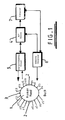
- Figure 1 illustrates an apparatus for putting the invention into effect.
- a subject's head 1 has adhered to it sixteen electrodes e1 to e16 distributed in a plane around the head. In some circumstances it may be preferred to have a non-planar distribution of electrodes as described in Polydorides N., Lionheart W.R.B., and McCann, H.: "Krylov Subspace Iterative Techniques: On the detection of brain activity with electrical impedance tomography" IEEE Transactions on Medical Imaging, Volume 21, No 6, June 2002 pages 596-603.
- the subject's ears 2 and nose 3 are schematically illustrated to indicate the orientation of the subject's head.
- Calibrated headphones are provided to deliver an auditory evoked response (AER) stimulus to the subject's ears and goggles (not shown) are provided which include light emitting diodes for generating a visually evoked response (VER) stimulus.
- AER auditory evoked response
- goggles are provided which include light emitting diodes for generating a visually evoked response (VER) stimulus.
- Each of the sixteen electrodes is a silver-silver chloride EEG electrode of type, which present a relatively small contact impedance in the scalp.
- An EIT system 4 is provided to deliver current to selected pairs of electrodes via a current limiting circuit 5 and to perform voltage measurements between other selected pairs of electrodes.
- a stimulus generator 6 also provides an input for the EIT system 4 such that EIT measurement can be effected at appropriate times relative to application of a stimulus.
- a computer 7 is provided to control the overall operation of the system and to log experimental results.
- a stimulus such as a VER stimulus or an AER stimulus is applied to the subject.
- a current is passed between a first pair of electrodes for a predetermined period.
- current is injected between each pair of electrodes in turn.
- a series of voltage measurements are taken between pairs of electrodes.
- Figure 2 comprises three parts, an upper part indicating application of the stimulus (represented by a vertical bar), a central part indicating periods during which current is passed between selected pairs of electrodes, and a lower part indicating periods during which voltage measurements are made between selected pairs of electrodes.
- electrodes e1 and e9 twelve voltage values are measured between adjacent electrodes in sequence, that is electrodes e2-e3, e3-e4, e4-e5, e5-e6, e6-e7, e7-e8, e10-e11, e11-e12, e12-e13, e13-e14, e14-e15, and e15-e16. Some of these measurements are illustrated in the lower part of figure 2. No measurements are made between electrode pairs including either of the electrodes (e1 and e9) between which current is passed Each of the voltage measurements is taken over a period of 3.0 milliseconds with a delay of 0.18 milliseconds between successive measurements.
- the first voltage measurement is taken between electrodes e2 and e3, (electrode e1 being used for current injection) whereas the first voltage measurement during the second current injection period is taken between electrodes e3 and e4 (electrode e2 being used for current injection).
- the same rolling pattern of electrode selections continues through the full series of eight current injection periods.
- an image of the impedance distribution in the brain can be created using known image reconstruction algorithms (see for example "Krylov Subspace Iterative Techniques: on the detection of brain activity with electrical impedance tomography" as referred to above).
- image reconstruction algorithms see for example "Krylov Subspace Iterative Techniques: on the detection of brain activity with electrical impedance tomography” as referred to above).
- Such an image can then be viewed by a medical practitioner to determine whether or not the brain has responded to the application of the stimulus in a normal manner. That is, it is known from neurological models which part of the brain should be active at a predetermined t l value ( Figure 2) after application of a particular type of stimulus, and thus the image can be analysed to determine whether or not activity is present as expected in the brain.
- the time delay t l between application of the stimulus and initiation of the EIT measurement process may be variable by a user, using functionality provided by the computer 7 ( Figure 1).
- a plurality of images may be generated, by presenting a plurality of stimuli to the user, and initiating EIT measurement at a different t l value after application of each stimulus.
- a plurality of images can be created which can be arranged in order of increasing t l to represent changing brain activity at different times following application of a stimulus.
- the computer 7 may be programmed to control the stimulus generator 6 to present the plurality of stimuli, take the necessary measurements at various times after stimulus application, and present the results to the user.
- the computer may be programmed so as to expect a user specified t l value, apply a stimulus, initiate EIT measurement after the user specified time delay, and create an image using the measurements obtained. Upon reviewing the created image, the user may determine that further images need to be generated at different specific t l values, and thus further single images can be created.
- the computer 7 is programmed to apply a plurality of stimuli, and generate a plurality of images at different t l values, delays between successive stimuli are varied in a random manner so as to avoid the subject's brain being "trained” to expect stimuli at particular times. Furthermore, the delay times between different stimuli and the initiation of EIT measurement can be varied in a random manner. Thus images are not generally generated in order of increasing time delay.
- FIG. 3 there are illustrated six impedance measurements generated at different delays after the application of a visual stimulus.
- the top left hand image of Figure 3 was generated by starting EIT measurement at approximately 80 milliseconds after the application of a visual stimulus.
- the lateral geniculate neucleus (LGN) 8 is shown as being active at the time at which this image was generated. At this time, the LGN was receiving information on brightness and location of the visual stimulus, originating from the rods of the retina.
- the LGN receives an input from the optic nerve.
- the LGN is active through most visual processing as can be seen from the six images of Figure 3.
- the upper centre image of Figure 3 was generated by starting EIT measurement at approximately 105 milliseconds after the application of a visual stimulus.
- the LGN 8 is still active but at this time neurological modelling shows that information on the colour of the visual stimulus is being processed, originating from the cones of the retina.
- Brightness and contour information is processed in an area 9 (known as area V1), at the back of the brain.
- area V1 is brighter in this image, indicating the expected activity.
- the upper right image was generated by starting EIT measurement at 137 milliseconds after the application of a visual stimulus. It can be seen that activity in the area 9 has increased considerably with this part of the brain working to integrate colour stereo and texture information, ready for relay to higher brain regions. In addition, feedback information is being relayed back to the LGN 8 in order to fine tune its processing of future information. Intense activity in LGN area 8 and increased activity in V1 area 9 is indicated in this image.
- the lower centre image of Figure 3 was generated by starting EIT measurement at 201 milliseconds after the application of a visual stimulus.
- Large dark areas 12, 13, 14 correspond to activity in the left anterior cingulate gyrus and connected regions of the limbic system. These regions are responsible for many things, but most relevant here is the emotion accompanying the recognition of an object. These same regions 12, 13, 14 are responsible for deciding whether a noxious stimulus is actually painful. In the present circumstance, we can assume that these areas of the brain are determining information of the form "that was another flash". It is not surprising that imaging using this technique is able to directly visualise human emotions arising as a result of the sensory stimulus.
- the lower right image of figure 3 was generated by starting EIT measurement at 248 milliseconds after the application of a visual stimulus. Most visual processing is complete by this stage and higher brain regions are determining the action to be taken in response to the received information. Large parts of the brain are preparing for any subsequent flash, and thus there is a need for random sequences of flashes to eliminate habituation as described above.
- the described system could be used to assist in the diagnosis of a patient presenting with blindness.
- Application of a visual stimulus to the patient and examination of an image or images of the patient's brain created using the above-described EIT technique will allow analysis of the cause of blindness.
- a medical practitioner will know where in the brain activity can be expected at particular delay times after stimulus application. If any brain activity is observed, clearly the retina is not detached as signals are being sent to the brain, thus indicating that the blindness may be caused by brain damage. If however no response is observed in the brain to the stimulus, the cause could either be a detached retina, or more serious brain damage. If some brain activity is observed, images can be taken at different delay times after stimulus application, such that images created after a particular time delay do not show expected behaviour. The medical practitioner is therefore provided with an indication of the location of the brain damage.
- an embodiment of the present invention may be used to image brain condition. Electrodes are applied to the patient's head as illustrated in figure 1 and as described above. Stimuli are then presented to the patient and response monitored. A nerve stimulator is placed on the patient's leg, and triggered to provide a number of unequally temporally spaced stimuli; at a predetermined time after each stimulus, an EIT measurement is taken creating an image as described above.
- an audio stimulus is provided and a series of images is again created.
- a visual stimulus is provided and a number of images created.
- the three sets of images created, each in response to a different type of stimulus, allow a thorough assessment of brain function to be made, thus allowing evaluation of the severity of the stroke.
- the imaging apparatus required for this procedure is relatively small in size, and relatively cheap to provide.
- the apparatus may be provided to a general practitioner, allowing him to quickly and easily assess the need for a patient to be referred to a neurologist.
- each set of measurements is accumulated after a respective stimulating event, all the sets of measurements could be accumulated after a single stimulating event. If the invention is to be implemented in this way, EIT techniques must be used which allow relatively fast current injection and voltage measurement so as to allow images to be captured with the required temporal resolution.
- the specific parts of the brain that need to be imaged can be identified.
- the number of current injections required can be reduced from the eight injections described with reference to Figure 2 to one or two carefully selected injections.
- the visual pathway current may be passed between regions at the front and the back of the head. That is, injection is parallel to the visual pathway which generally runs from the eyes to the back of the brain.
- the pathway from the ears to auditory cortex at the side of the brain needs to be monitored, and so electrodes must be placed at least at the side of the head.
- a parallel voltage measurement protocol may be used. This makes it possible to dramatically reduce the time taken to capture the required measurement data.
- all current injections described with reference to Figure 2 may be used, but only a limited number of voltage measurements taken for each injection.
- both the injections and measurements may be selected on the basis of a neurological model and the applied stimulus.
- each stimulating event is of short duration.
- a stimulating event could however be relatively prolonged, extending into a subsequent period during which impedance measurements are made.
- the measurement data may be processed to reduce sensitivity to effects such as noise and the temporal variation of impedance within the brain during the measurement sequence.
- a Kalman filter may be used in a conventional manner.
- a plurality of stimulus may be applied, and a number of sets of voltage measurements collected at a particular time after application of each respective stimulus. Sets of voltage measurements collected in this way can then be averaged so as to provide greater accuracy.
Landscapes
- Health & Medical Sciences (AREA)
- Life Sciences & Earth Sciences (AREA)
- Neurology (AREA)
- Heart & Thoracic Surgery (AREA)
- Molecular Biology (AREA)
- Nuclear Medicine, Radiotherapy & Molecular Imaging (AREA)
- Biophysics (AREA)
- Pathology (AREA)
- Engineering & Computer Science (AREA)
- Biomedical Technology (AREA)
- Neurosurgery (AREA)
- Medical Informatics (AREA)
- Physics & Mathematics (AREA)
- Surgery (AREA)
- Animal Behavior & Ethology (AREA)
- General Health & Medical Sciences (AREA)
- Public Health (AREA)
- Veterinary Medicine (AREA)
- Physiology (AREA)
- Radiology & Medical Imaging (AREA)
- Measurement And Recording Of Electrical Phenomena And Electrical Characteristics Of The Living Body (AREA)
Claims (17)
- Procédé pour surveiller la réponse du système nerveux d'un corps (1) à un stimulus, comprenant la collecte d'un jeu de mesures de tension entre des zones sélectionnées sur une surface du corps tandis qu'un courant est injecté et est passé entre des régions sélectionnées de la surface du corps (1), dans lequel le jeu de mesures de tension est collecté sur une période de mesure prédéterminée, la période de mesure prédéterminée est initiée à un temps prédéterminé (t1) après l'application du stimulus, et les mesures de tension collectées sont comparées à des mesures de référence afin d'évaluer un comportement neurobiologique du système nerveux.
- Procédé selon la revendication 1, dans lequel le jeu de mesures de tension est utilisé pour produire une image qui représente la distribution d'impédance à l'intérieur du corps (1).
- Procédé selon la revendication 1 ou 2, dans lequel le stimulus comprend une série de stimuli, un jeu de mesures de tension est collecté pendant des périodes d'injection de courant initiées après l'application de chaque stimulus, la collecte de mesures de tension rapportées à chaque stimulus est initiée à un temps retardé par rapport au stimulus respectif, le retard temporel diffère pour chaque stimulus et des différences entre des jeux collectés de mesures de tension sont interprétées en tant que variations représentatives de l'activité du système nerveux sur la différence temporelle entre les retards temporels respectifs.
- Procédé selon la revendication 3 lorsqu'elle dépend de la revendication 2, dans lequel les images sont comparées pour identifier des variations de l'activité du système nerveux.
- Procédé selon l'une quelconque des revendications précédentes, dans lequel le stimulus appliqué est un stimulus visuel ou auditif.
- Procédé selon l'une quelconque des revendications précédentes, dans lequel les mesures de tension mesurées sont filtrées en utilisant un filtre de Kalman.
- Procédé selon l'une quelconque des revendications précédentes, comprenant en outre l'application du stimulus.
- Procédé selon l'une quelconque des revendications 1 à 6, dans lequel l'application du stimulus est détectée et ladite détection démarre le calcul dudit temps prédéterminé.
- Procédé selon la revendication 8, dans lequel le stimulus survient spontanément.
- Procédé selon la revendication 9, dans lequel le stimulus est une caractéristique d'un environnement dans lequel le corps est localisé.
- Procédé selon la revendication 1, dans lequel le procédé comprend en outre la surveillance de la réponse d'une partie prédéterminée du système nerveux d'un corps (1) au stimulus appliqué et l'identification de la partie prédéterminée du système nerveux, dans lequel lesdites régions et/ou zones sont sélectionnées sur la base d'un modèle neurologique du système nerveux et du stimulus appliqué de telle sorte qu'une sensibilité des mesures d'impédance dérivées à des variations de la partie prédéterminée du système nerveux soit maximisée.
- Procédé selon la revendication 11, dans lequel les mesures d'impédance dérivées sont comparées à des mesures de référence pour déterminer une réponse normale ou anormale du système nerveux.
- Procédé selon la revendication 11 ou 12, dans lequel le stimulus est un stimulus visuel ou auditif.
- Procédé selon l'une quelconque des revendications 1 à 10, utilisé en combinaison avec un procédé selon l'une quelconque des revendications 11 à 13.
- Appareil pour surveiller la réponse du système nerveux d'un corps à un stimulus appliqué comprenant un moyen pour appliquer le stimulus au corps (1), un moyen pour injecter et faire passer un courant entre des régions sélectionnées de la surface d'un corps et un moyen pour collecter un jeu de mesures de tension entre des zones sélectionnées sur la surface du corps, le moyen pour collecter des mesures de tension étant configuré pour collecter lesdites mesures de tension tandis que ledit courant est en train d'être injecté et passé, dans lequel l'appareil est configuré pour collecter le jeu de mesures de tension sur une période de mesure prédéterminée et est configuré pour initier la période de mesure prédéterminée à un temps prédéterminé (t1) après l'application du stimulus, et des moyens sont prévus pour comparer les mesures de tension collectées à des mesures de référence afin d'évaluer un comportement neurobiologique du système nerveux.
- Appareil selon la revendication 15, dans lequel l'appareil est adapté pour surveiller la réponse d'une partie prédéterminée du système nerveux d'un corps (1) au stimulus appliqué, dans lequel lesdites régions et/ou zones sont sélectionnées sur la base d'un modèle neurologique du système nerveux et du stimulus appliqué tel que la sensibilité des mesures d'impédance dérivées à des variations de la partie prédéterminée du système nerveux est maximisée.
- Programme d'ordinateur qui code le procédé selon l'une quelconque des revendications 1 à 14, le programme étant stocké sur un support de données.
Applications Claiming Priority (2)
| Application Number | Priority Date | Filing Date | Title |
|---|---|---|---|
| GBGB0309049.5A GB0309049D0 (en) | 2003-04-22 | 2003-04-22 | Nervous system monitoring method |
| PCT/GB2004/001565 WO2004093679A1 (fr) | 2003-04-22 | 2004-04-13 | Procede de surveillance du systeme nerveux |
Publications (2)
| Publication Number | Publication Date |
|---|---|
| EP1615550A1 EP1615550A1 (fr) | 2006-01-18 |
| EP1615550B1 true EP1615550B1 (fr) | 2007-03-21 |
Family
ID=9957052
Family Applications (1)
| Application Number | Title | Priority Date | Filing Date |
|---|---|---|---|
| EP04727037A Expired - Lifetime EP1615550B1 (fr) | 2003-04-22 | 2004-04-13 | Procede de surveillance du systeme nerveux |
Country Status (5)
| Country | Link |
|---|---|
| US (1) | US8088076B2 (fr) |
| EP (1) | EP1615550B1 (fr) |
| DE (1) | DE602004005438T2 (fr) |
| GB (1) | GB0309049D0 (fr) |
| WO (1) | WO2004093679A1 (fr) |
Cited By (3)
| Publication number | Priority date | Publication date | Assignee | Title |
|---|---|---|---|---|
| WO2010112825A3 (fr) * | 2009-03-31 | 2010-11-25 | The University Of Manchester | Méthode de surveillance du système nerveux |
| WO2014025353A1 (fr) * | 2012-08-09 | 2014-02-13 | Northeastern University | Encéphalographie de champ électrique : détection et surveillance de signal cérébral à base de champ électrique |
| US10912480B2 (en) | 2013-06-21 | 2021-02-09 | Northeastern University | Sensor system and process for measuring electric activity of the brain, including electric field encephalography |
Families Citing this family (11)
| Publication number | Priority date | Publication date | Assignee | Title |
|---|---|---|---|---|
| US8367254B2 (en) | 2003-09-05 | 2013-02-05 | Lg Chem, Ltd. | Electrolyte for a high voltage battery and lithium secondary battery comprising the same |
| KR100657225B1 (ko) | 2003-09-05 | 2006-12-14 | 주식회사 엘지화학 | 전지의 안전성을 향상시키기 위한 전해액 용매 및 이를포함하는 리튬 이차 전지 |
| EP1767146A1 (fr) * | 2005-09-21 | 2007-03-28 | Max-Planck-Gesellschaft zur Förderung der Wissenschaften e.V. | Surveillance des signaux neuronaux |
| JP5340967B2 (ja) * | 2007-03-15 | 2013-11-13 | コーニンクレッカ フィリップス エヌ ヴェ | 中核体温を測定するための方法及び装置 |
| DE102008039844A1 (de) * | 2008-08-27 | 2010-03-04 | Fresenius Medical Care Deutschland Gmbh | Tastkopf mit wenigstens zwei Elektroden zur Impedanzmessung, Anordnung und Verfahren hierzu |
| US20100250325A1 (en) * | 2009-03-24 | 2010-09-30 | Neurofocus, Inc. | Neurological profiles for market matching and stimulus presentation |
| GB0907983D0 (en) | 2009-05-09 | 2009-06-24 | Univ Manchester | Tomographic data acquisition apparatus |
| US9345411B2 (en) * | 2011-02-09 | 2016-05-24 | Orsan Medical Technologies, Ltd. | Devices and methods for monitoring cerebral hemodynamic conditions |
| US10357177B2 (en) | 2013-12-13 | 2019-07-23 | General Electric Company | Systems and methods for electrical impedance imaging |
| WO2022081470A1 (fr) * | 2020-10-13 | 2022-04-21 | Duke University | Systèmes et procédés pour l'optimisation spatiale de la stimulation de la moelle épinière |
| CN115067921B (zh) * | 2022-06-14 | 2023-06-13 | 杭州永川科技有限公司 | 基于脑电阻抗数据的体外循环术神经功能损伤预测系统 |
Family Cites Families (13)
| Publication number | Priority date | Publication date | Assignee | Title |
|---|---|---|---|---|
| US4421122A (en) * | 1981-05-15 | 1983-12-20 | The Children's Medical Center Corporation | Brain electrical activity mapping |
| US4862359A (en) * | 1984-08-31 | 1989-08-29 | Bio-Logic Systems Corporation | Topographical mapping of brain functionality from neuropsychological test results |
| US5143081A (en) * | 1990-07-27 | 1992-09-01 | New York University | Randomized double pulse stimulus and paired event analysis |
| JP2596372B2 (ja) * | 1994-04-21 | 1997-04-02 | 日本電気株式会社 | 誘発電位測定装置 |
| US5919142A (en) * | 1995-06-22 | 1999-07-06 | Btg International Limited | Electrical impedance tomography method and apparatus |
| US6385486B1 (en) * | 1997-08-07 | 2002-05-07 | New York University | Brain function scan system |
| AUPQ646500A0 (en) * | 2000-03-27 | 2000-04-20 | Australian National University, The | Method and apparatus for assessing neural function by sparse stimuli |
| US6757558B2 (en) * | 2000-07-06 | 2004-06-29 | Algodyne, Ltd. | Objective pain measurement system and method |
| DE10104153A1 (de) | 2001-01-30 | 2002-06-06 | Siemens Audiologische Technik | Verfahren sowie Apparatur zur individuellen Anpassung von Instrumenten zur auditorischen Stimulation an eine Person |
| CA2449567A1 (fr) * | 2001-06-13 | 2002-12-19 | Ckm Diagnostics, Inc. | Procede et appareil non invasif pour detection de tissu |
| US6936012B2 (en) * | 2001-06-18 | 2005-08-30 | Neurometrix, Inc. | Method and apparatus for identifying constituent signal components from a plurality of evoked physiological composite signals |
| US7089927B2 (en) * | 2002-10-23 | 2006-08-15 | New York University | System and method for guidance of anesthesia, analgesia and amnesia |
| AU2005254076A1 (en) * | 2004-06-14 | 2005-12-29 | Cephos Corp. | Systems and methods for detecting deception by measuring brain activity |
-
2003
- 2003-04-22 GB GBGB0309049.5A patent/GB0309049D0/en not_active Ceased
-
2004
- 2004-04-13 EP EP04727037A patent/EP1615550B1/fr not_active Expired - Lifetime
- 2004-04-13 US US10/553,745 patent/US8088076B2/en not_active Expired - Fee Related
- 2004-04-13 DE DE602004005438T patent/DE602004005438T2/de not_active Expired - Lifetime
- 2004-04-13 WO PCT/GB2004/001565 patent/WO2004093679A1/fr not_active Ceased
Cited By (5)
| Publication number | Priority date | Publication date | Assignee | Title |
|---|---|---|---|---|
| WO2010112825A3 (fr) * | 2009-03-31 | 2010-11-25 | The University Of Manchester | Méthode de surveillance du système nerveux |
| GB2481945A (en) * | 2009-03-31 | 2012-01-11 | Univ Manchester | Nervous system monitoring method |
| WO2014025353A1 (fr) * | 2012-08-09 | 2014-02-13 | Northeastern University | Encéphalographie de champ électrique : détection et surveillance de signal cérébral à base de champ électrique |
| US11083401B2 (en) | 2012-08-09 | 2021-08-10 | Northeastern University | Electric field encephalography: electric field based brain signal detection and monitoring |
| US10912480B2 (en) | 2013-06-21 | 2021-02-09 | Northeastern University | Sensor system and process for measuring electric activity of the brain, including electric field encephalography |
Also Published As
| Publication number | Publication date |
|---|---|
| US20060189883A1 (en) | 2006-08-24 |
| EP1615550A1 (fr) | 2006-01-18 |
| WO2004093679A1 (fr) | 2004-11-04 |
| DE602004005438T2 (de) | 2007-11-29 |
| GB0309049D0 (en) | 2003-05-28 |
| DE602004005438D1 (de) | 2007-05-03 |
| US8088076B2 (en) | 2012-01-03 |
Similar Documents
| Publication | Publication Date | Title |
|---|---|---|
| US12303285B2 (en) | Methods and magnetic imaging devices to inventory human brain cortical function | |
| Sutherland et al. | Reliable detection of bilateral activation in human primary somatosensory cortex by unilateral median nerve stimulation | |
| US10258291B2 (en) | Systems and methods for evaluation of neuropathologies | |
| Leonard et al. | Neurons in the amygdala of the monkey with responses selective for faces | |
| EP1615550B1 (fr) | Procede de surveillance du systeme nerveux | |
| US11839475B2 (en) | Methods and magnetic imaging devices to inventory human brain cortical function | |
| US20100010369A1 (en) | Nervous system monitoring method | |
| Miller et al. | Rapid online language mapping with electrocorticography | |
| KR20250041127A (ko) | 알츠하이머병 환자의 뇌 교란에 대한 개별 반응을 특성화하는 시스템 및 방법 | |
| Chang et al. | Assessing recurrent interactions in cortical networks: Modeling EEG response to transcranial magnetic stimulation | |
| Mahmutoglu et al. | Simultaneous EEG/MEG yields complementary information of nociceptive evoked responses | |
| WO2010112825A2 (fr) | Méthode de surveillance du système nerveux | |
| EP2822459B1 (fr) | Système et procédé de détermination améliorée d'un état de réponse du cerveau | |
| Kasten et al. | Integrating electric field modelling and neuroimaging to explain variability of low intensity tES effects | |
| McCann et al. | Sub-second functional imaging by electrical impedance tomography | |
| TWI813222B (zh) | 用於評估疼痛敏感度的大腦活動量測方法與系統 | |
| KR20240158996A (ko) | 다초점 응답들에서 동적 응답 이득 변화들을 효율적으로 캡처하기 위한 응답 추정 | |
| König | Online Source Analysis for Guiding TMS–EEG Measurements | |
| Schmidt | Into the deep |
Legal Events
| Date | Code | Title | Description |
|---|---|---|---|
| PUAI | Public reference made under article 153(3) epc to a published international application that has entered the european phase |
Free format text: ORIGINAL CODE: 0009012 |
|
| 17P | Request for examination filed |
Effective date: 20051005 |
|
| AK | Designated contracting states |
Kind code of ref document: A1 Designated state(s): AT BE BG CH CY CZ DE DK EE ES FI FR GB GR HU IE IT LI LU MC NL PL PT RO SE SI SK TR |
|
| AX | Request for extension of the european patent |
Extension state: AL HR LT LV MK |
|
| DAX | Request for extension of the european patent (deleted) | ||
| RBV | Designated contracting states (corrected) |
Designated state(s): DE FR GB |
|
| 17Q | First examination report despatched |
Effective date: 20060116 |
|
| GRAP | Despatch of communication of intention to grant a patent |
Free format text: ORIGINAL CODE: EPIDOSNIGR1 |
|
| GRAS | Grant fee paid |
Free format text: ORIGINAL CODE: EPIDOSNIGR3 |
|
| GRAA | (expected) grant |
Free format text: ORIGINAL CODE: 0009210 |
|
| AK | Designated contracting states |
Kind code of ref document: B1 Designated state(s): DE FR GB |
|
| REG | Reference to a national code |
Ref country code: GB Ref legal event code: FG4D |
|
| REF | Corresponds to: |
Ref document number: 602004005438 Country of ref document: DE Date of ref document: 20070503 Kind code of ref document: P |
|
| ET | Fr: translation filed | ||
| PLBE | No opposition filed within time limit |
Free format text: ORIGINAL CODE: 0009261 |
|
| STAA | Information on the status of an ep patent application or granted ep patent |
Free format text: STATUS: NO OPPOSITION FILED WITHIN TIME LIMIT |
|
| PG25 | Lapsed in a contracting state [announced via postgrant information from national office to epo] |
Ref country code: DE Free format text: LAPSE BECAUSE OF NON-PAYMENT OF DUE FEES Effective date: 20071101 |
|
| 26N | No opposition filed |
Effective date: 20071227 |
|
| GBPC | Gb: european patent ceased through non-payment of renewal fee |
Effective date: 20080413 |
|
| REG | Reference to a national code |
Ref country code: GB Ref legal event code: S28 Free format text: APPLICATION FILED |
|
| REG | Reference to a national code |
Ref country code: FR Ref legal event code: ST Effective date: 20090228 |
|
| PG25 | Lapsed in a contracting state [announced via postgrant information from national office to epo] |
Ref country code: FR Free format text: LAPSE BECAUSE OF NON-PAYMENT OF DUE FEES Effective date: 20070430 |
|
| REG | Reference to a national code |
Ref country code: GB Ref legal event code: S28 Free format text: RESTORATION ALLOWED Effective date: 20090513 |
|
| REG | Reference to a national code |
Ref country code: FR Ref legal event code: RN |
|
| REG | Reference to a national code |
Ref country code: FR Ref legal event code: FC |
|
| PG25 | Lapsed in a contracting state [announced via postgrant information from national office to epo] |
Ref country code: GB Free format text: LAPSE BECAUSE OF NON-PAYMENT OF DUE FEES Effective date: 20080413 |
|
| PGRI | Patent reinstated in contracting state [announced from national office to epo] |
Ref country code: FR Effective date: 20090513 |
|
| PGRI | Patent reinstated in contracting state [announced from national office to epo] |
Ref country code: FR Effective date: 20090513 |
|
| PGRI | Patent reinstated in contracting state [announced from national office to epo] |
Ref country code: DE Effective date: 20091103 |
|
| PGRI | Patent reinstated in contracting state [announced from national office to epo] |
Ref country code: FR Effective date: 20100120 |
|
| PGFP | Annual fee paid to national office [announced via postgrant information from national office to epo] |
Ref country code: DE Payment date: 20120425 Year of fee payment: 9 |
|
| PGFP | Annual fee paid to national office [announced via postgrant information from national office to epo] |
Ref country code: FR Payment date: 20120504 Year of fee payment: 9 Ref country code: GB Payment date: 20120411 Year of fee payment: 9 |
|
| GBPC | Gb: european patent ceased through non-payment of renewal fee |
Effective date: 20130413 |
|
| PG25 | Lapsed in a contracting state [announced via postgrant information from national office to epo] |
Ref country code: DE Free format text: LAPSE BECAUSE OF NON-PAYMENT OF DUE FEES Effective date: 20131101 Ref country code: GB Free format text: LAPSE BECAUSE OF NON-PAYMENT OF DUE FEES Effective date: 20130413 |
|
| REG | Reference to a national code |
Ref country code: FR Ref legal event code: ST Effective date: 20131231 |
|
| REG | Reference to a national code |
Ref country code: DE Ref legal event code: R119 Ref document number: 602004005438 Country of ref document: DE Effective date: 20131101 |
|
| PG25 | Lapsed in a contracting state [announced via postgrant information from national office to epo] |
Ref country code: FR Free format text: LAPSE BECAUSE OF NON-PAYMENT OF DUE FEES Effective date: 20130430 |