EP1616368B1 - Antennensystem für ein kraftfahrzeug - Google Patents
Antennensystem für ein kraftfahrzeug Download PDFInfo
- Publication number
- EP1616368B1 EP1616368B1 EP04729070A EP04729070A EP1616368B1 EP 1616368 B1 EP1616368 B1 EP 1616368B1 EP 04729070 A EP04729070 A EP 04729070A EP 04729070 A EP04729070 A EP 04729070A EP 1616368 B1 EP1616368 B1 EP 1616368B1
- Authority
- EP
- European Patent Office
- Prior art keywords
- antenna
- antenna system
- space
- filling
- radio
- Prior art date
- Legal status (The legal status is an assumption and is not a legal conclusion. Google has not performed a legal analysis and makes no representation as to the accuracy of the status listed.)
- Expired - Lifetime
Links
- 230000001413 cellular effect Effects 0.000 claims abstract description 37
- 230000008878 coupling Effects 0.000 claims abstract description 11
- 238000010168 coupling process Methods 0.000 claims abstract description 11
- 238000005859 coupling reaction Methods 0.000 claims abstract description 11
- 230000010287 polarization Effects 0.000 claims description 13
- 230000010354 integration Effects 0.000 claims description 12
- 239000003989 dielectric material Substances 0.000 claims description 8
- 239000000758 substrate Substances 0.000 claims description 7
- IRLPACMLTUPBCL-KQYNXXCUSA-N 5'-adenylyl sulfate Chemical compound C1=NC=2C(N)=NC=NC=2N1[C@@H]1O[C@H](COP(O)(=O)OS(O)(=O)=O)[C@@H](O)[C@H]1O IRLPACMLTUPBCL-KQYNXXCUSA-N 0.000 claims description 2
- 239000004020 conductor Substances 0.000 description 29
- 230000005855 radiation Effects 0.000 description 17
- 238000000034 method Methods 0.000 description 13
- 230000005404 monopole Effects 0.000 description 13
- 238000005549 size reduction Methods 0.000 description 11
- 230000005540 biological transmission Effects 0.000 description 10
- 230000009467 reduction Effects 0.000 description 7
- 230000008901 benefit Effects 0.000 description 6
- 238000013461 design Methods 0.000 description 5
- 238000004519 manufacturing process Methods 0.000 description 4
- 238000007493 shaping process Methods 0.000 description 4
- 238000004364 calculation method Methods 0.000 description 3
- 238000004891 communication Methods 0.000 description 3
- 230000006872 improvement Effects 0.000 description 3
- 239000000463 material Substances 0.000 description 3
- 230000003094 perturbing effect Effects 0.000 description 3
- 230000008859 change Effects 0.000 description 2
- 238000007796 conventional method Methods 0.000 description 2
- 239000011521 glass Substances 0.000 description 2
- 238000004806 packaging method and process Methods 0.000 description 2
- 230000003071 parasitic effect Effects 0.000 description 2
- 230000000007 visual effect Effects 0.000 description 2
- 239000013585 weight reducing agent Substances 0.000 description 2
- 230000006978 adaptation Effects 0.000 description 1
- 238000013459 approach Methods 0.000 description 1
- 230000004071 biological effect Effects 0.000 description 1
- 238000010276 construction Methods 0.000 description 1
- 230000003247 decreasing effect Effects 0.000 description 1
- 230000001419 dependent effect Effects 0.000 description 1
- 230000008030 elimination Effects 0.000 description 1
- 238000003379 elimination reaction Methods 0.000 description 1
- 238000005516 engineering process Methods 0.000 description 1
- 230000000763 evoking effect Effects 0.000 description 1
- 238000005562 fading Methods 0.000 description 1
- 239000005357 flat glass Substances 0.000 description 1
- 239000003365 glass fiber Substances 0.000 description 1
- 230000001939 inductive effect Effects 0.000 description 1
- 230000003993 interaction Effects 0.000 description 1
- 229910052741 iridium Inorganic materials 0.000 description 1
- GKOZUEZYRPOHIO-UHFFFAOYSA-N iridium atom Chemical compound [Ir] GKOZUEZYRPOHIO-UHFFFAOYSA-N 0.000 description 1
- 230000035515 penetration Effects 0.000 description 1
- 229920000728 polyester Polymers 0.000 description 1
- 230000035755 proliferation Effects 0.000 description 1
- 239000007787 solid Substances 0.000 description 1
- 238000010561 standard procedure Methods 0.000 description 1
- 238000006467 substitution reaction Methods 0.000 description 1
- 230000037072 sun protection Effects 0.000 description 1
- 230000001629 suppression Effects 0.000 description 1
Images









Classifications
-
- H—ELECTRICITY
- H01—ELECTRIC ELEMENTS
- H01Q—ANTENNAS, i.e. RADIO AERIALS
- H01Q1/00—Details of, or arrangements associated with, antennas
- H01Q1/27—Adaptation for use in or on movable bodies
- H01Q1/32—Adaptation for use in or on road or rail vehicles
- H01Q1/325—Adaptation for use in or on road or rail vehicles characterised by the location of the antenna on the vehicle
- H01Q1/3291—Adaptation for use in or on road or rail vehicles characterised by the location of the antenna on the vehicle mounted in or on other locations inside the vehicle or vehicle body
-
- H—ELECTRICITY
- H01—ELECTRIC ELEMENTS
- H01Q—ANTENNAS, i.e. RADIO AERIALS
- H01Q1/00—Details of, or arrangements associated with, antennas
- H01Q1/12—Supports; Mounting means
- H01Q1/1271—Supports; Mounting means for mounting on windscreens
-
- H—ELECTRICITY
- H01—ELECTRIC ELEMENTS
- H01Q—ANTENNAS, i.e. RADIO AERIALS
- H01Q1/00—Details of, or arrangements associated with, antennas
- H01Q1/27—Adaptation for use in or on movable bodies
- H01Q1/32—Adaptation for use in or on road or rail vehicles
- H01Q1/3208—Adaptation for use in or on road or rail vehicles characterised by the application wherein the antenna is used
-
- H—ELECTRICITY
- H01—ELECTRIC ELEMENTS
- H01Q—ANTENNAS, i.e. RADIO AERIALS
- H01Q1/00—Details of, or arrangements associated with, antennas
- H01Q1/27—Adaptation for use in or on movable bodies
- H01Q1/32—Adaptation for use in or on road or rail vehicles
- H01Q1/325—Adaptation for use in or on road or rail vehicles characterised by the location of the antenna on the vehicle
- H01Q1/3266—Adaptation for use in or on road or rail vehicles characterised by the location of the antenna on the vehicle using the mirror of the vehicle
-
- H—ELECTRICITY
- H01—ELECTRIC ELEMENTS
- H01Q—ANTENNAS, i.e. RADIO AERIALS
- H01Q1/00—Details of, or arrangements associated with, antennas
- H01Q1/36—Structural form of radiating elements, e.g. cone, spiral, umbrella; Particular materials used therewith
-
- H—ELECTRICITY
- H01—ELECTRIC ELEMENTS
- H01Q—ANTENNAS, i.e. RADIO AERIALS
- H01Q1/00—Details of, or arrangements associated with, antennas
- H01Q1/36—Structural form of radiating elements, e.g. cone, spiral, umbrella; Particular materials used therewith
- H01Q1/38—Structural form of radiating elements, e.g. cone, spiral, umbrella; Particular materials used therewith formed by a conductive layer on an insulating support
-
- H—ELECTRICITY
- H01—ELECTRIC ELEMENTS
- H01Q—ANTENNAS, i.e. RADIO AERIALS
- H01Q21/00—Antenna arrays or systems
- H01Q21/28—Combinations of substantially independent non-interacting antenna units or systems
-
- H—ELECTRICITY
- H01—ELECTRIC ELEMENTS
- H01Q—ANTENNAS, i.e. RADIO AERIALS
- H01Q9/00—Electrically-short antennas having dimensions not more than twice the operating wavelength and consisting of conductive active radiating elements
- H01Q9/04—Resonant antennas
- H01Q9/0407—Substantially flat resonant element parallel to ground plane, e.g. patch antenna
- H01Q9/0428—Substantially flat resonant element parallel to ground plane, e.g. patch antenna radiating a circular polarised wave
-
- H—ELECTRICITY
- H01—ELECTRIC ELEMENTS
- H01Q—ANTENNAS, i.e. RADIO AERIALS
- H01Q9/00—Electrically-short antennas having dimensions not more than twice the operating wavelength and consisting of conductive active radiating elements
- H01Q9/04—Resonant antennas
- H01Q9/06—Details
- H01Q9/065—Microstrip dipole antennas
Definitions
- the technology described in this patent application relates to the field of antennas. More particularly, the application describes an antenna system of a motor vehicle.
- This invention includes a multiservice antenna system that may, for example, be integrated in a plastic cover fixed in the inner surface of the transparent windshield of a motor vehicle.
- the invention includes miniaturized antennas for the basic services currently required in a car, namely, the radio reception, preferably within the AM and FM or DAB bands, the cellular telephony for transmitting and receiving in the GSM 900, GSM 1800 and UMTS bands, and the GPS navigation system.
- the antenna shape and design are based on combined miniaturization techniques which permit a substantial size reduction of the antenna making possible its integration into a vehicle component such as, for instance, a rearview mirror.
- the telecommunication services included in an automobile were limited to a few systems, mainly analog radio reception (AM/FM bands).
- the most common solution for these systems is the typical whip antenna mounted on the car roof.
- the current tendency in the automotive sector is to reduce the aesthetic and aerodynamic impact of such whip antennas by embedding the antenna system in the vehicle structure.
- a major integration of the several telecommunication services into a single antenna is especially attractive to reduce the manufacturing cost or the damage due to vandalism and car wash systems.
- Antenna integration is becoming more and more necessary due to a deep cultural change towards an information society.
- the Internet has evoked an information age in which people around the globe expect, demand, and receive information.
- Car drivers expect to be able to drive safely while handling e-mail and telephone calls and obtaining directions, schedules, and other information accessible on the world wide web (WWW).
- Telematic devices can be used to automatically notify authorities of an accident and guide rescuers to the car, track stolen vehicles, provide navigation assistance to drivers, call emergency roadside assistance, and provide remote engine diagnostics.
- An antenna is said to be a small antenna (a miniature antenna) when it can fit into a small space compared to the operating wavelength. It is known that a small antenna features a large input reactance (either capacitive or inductive) that usually has to be compensated for with an external matching/loading circuit or structure. Other characteristics of a small antenna are its small radiating resistance, small bandwidth and low efficiency. Thus, it is highly challenging to pack a resonant antenna into a space that is small in terms of the wavelength at resonance.
- the space-filling curves introduced for the design and construction of small antennas improve the performance of other classical antennas described in the prior art (such as linear monopoles, dipoles and circular or rectangular loops).
- Patent US4123756 is one of the first to propose the utilization of conducting sheets as antennas inside of mirrors.
- Patent US5504478 proposed the use of the metallic sides of a mirror as an antenna for a wireless car aperture.
- Others configurations have been proposed to enclose a wireless car aperture, garage door opener or car alarm (Patent US5798688 ) inside the mirrors of motor vehicles.
- Patent US5798688 proposes a specific solution for determinate systems, which generally require a very narrow bandwidth antenna, and do not offer a full integration of basic service antennas.
- the present invention can use a rearview mirror to integrate all basic services required in a car, such as radio-broadcast, GPS and wireless access to cellular networks.
- the main advantages are a full antenna integration with no aesthetic or aerodynamic impact, second a full protection from accidental damage or vandalism, and a significant cost reduction.
- microstrip antennas The utilization of microstrip antennas is known in mobile telephony handsets (See, Paper by K.Virga and Y. Rahmat-Samii, "Low-Profile Enhanced-Bandwidth PIFA Antennas for Wireless Communications Packaging", published in IEEE Transactions on Microwave theory and Techniques in October 1997 ), especially in the configuration denoted as PIFA (Planar Inverted F Antennas).
- PIFA Planar Inverted F Antennas
- the reason for the utilization of microstrip PIFA antennas resides in their low profile, low fabrication costs, and easy integration within the hand-set structure. However, this antenna configuration has not been proposed for use in a motor vehicle.
- Several antenna configurations claimed by the present invention for the integration of a multiservice antenna system inside of an interior rearview mirror include the utilization of PIFA antennas.
- One of the miniaturization techniques used in the present invention is based, as noted above, on space-filling curves.
- the antenna shape could also be described as a multi-level structure. Multi-level techniques have already been proposed to reduce the physical dimensions of microstrip antennas ( PCT/ES/00296 ).
- WO 02/35646 describes an antenna according to the preamble of claim 1.
- WO 01/82 410 describes a similar antenna.
- An antenna system for a motor vehicle includes a radio antenna integrated with a physical component of a motor vehicle.
- the radio antenna has a radiating arm, with at least a portion of the radiating arm defining a space-filling curve.
- the radio antenna also has a feeding point for coupling the radio antenna to a radio receiver in the motor vehicle.
- an antenna system for a motor vehicle may include a plurality of antenna structures integrated within a physical component of the motor vehicle.
- the plurality of antenna structures includes a radio antenna and at least one of a cellular telephony antenna and a satellite-signal antenna.
- the radio antenna has a radiating arm, with at least a portion of the radiating arm defining a space-filling curve.
- the radio antenna also has a feeding point for coupling the radio antenna to a radio receiver in the motor vehicle.
- the radio antenna in the antenna system may include a radiating arm that defines a grid dimension curve.
- the present invention describes an integrated multiservice antenna system for a vehicle comprising the following parts and features:
- one of the preferred embodiments for the plastic cover enclosing the multiservice antenna system is the housing of the inside rearview mirror, including the rearview mirror support and/or the mirror itself. This position ensures an optimized antenna behavior, i.e. a good impedance matching, a substantially omnidirectional radiation pattern in the horizontal plane for covering terrestrial communication systems (like radio or cellular telephony), and a wide coverage in elevation for satellite communication systems, such as GPS.
- a space-filling curve can be described as a curve that is large in terms of physical length but small in terms of the area in which the curve can be included. More precisely, the following definition is taken in this document for a general space-filling curve, a curve composed by at least ten segments, said segments forming an angle with each adjacent segment. Regardless of the particular design of such space-filling curve is, it can never intersect with itself at any point except the initial and final point (that is, the whole curve can be arranged as a closed curve or loop, but none of the parts of the curve can become a closed loop).
- a space-filling curve can be fitted over a flat or curved surface, and due to the angles between segments, the physical length of the curve is always larger than that of any straight line that can be placed in the same area (surface) as said space-filling curve. Additionally, to properly shape the structure of a miniature antenna according to the present invention, the segments of the space-filling curves must be shorter than a tenth of the free-space operating wavelength.
- At least one of the antennas including a space-filling curve is characterized by a more restrictive feature: said curve is composed by at least two hundred segments, said segments forming a right angle with each adjacent segment, said segments being smaller than a hundredth of the free-space operating central wavelength.
- a possible antenna configuration may use said space-filling antenna as a monopole, where a conducting arm of said monopole is substantially described a space filling curve. The antenna is then fed with a two conductor structure such as a coaxial cable, with one of the conductors connected to the lower tip of the multilevel structure and the other conductor connected to the metallic structure of the car which acts as a ground counterpoise.
- antenna configurations can be used that feature a space-filling curve as the main characteristic, for example a dipole or a loop configuration.
- This antenna is suitable, for instance, for analog (FM/AM) or digital broadcast radio reception, depending on the final antenna size, as is apparent to anyone skilled in the art.
- Said antenna features a significant size reduction below 20% of the typical size of a conventional external quarter-wave whip antenna; this feature, together with the small profile of the antenna which may, for instance, be printed in a low cost dielectric substrate, allows a simple and compact integration of the antenna structure into a car component, such as inside of the rearview mirror.
- the antenna can also be used in at least certain transmission and reception application in the cellular telephone bands.
- PIFA Planar Inverted F Antenna
- the parallel conducting sheets are connected through a conducting strip near one of the corners and orthogonally mounted to both sheets.
- the antenna is fed through a coaxial cable that has its outer conductor connected to the first sheet.
- the second sheet is coupled either by direct contact or capacitively to the inner conductor of the coaxial cable.
- PIFA antennas are known for handsets and wireless terminals
- said configuration is used advantageously for integrating a wireless service into a vehicle.
- the main advantage is that due to the small size, low profile and characteristic radiation pattern, the PIFA antennas are fully integrated in a preferred configuration into the housing or mounting of the inner rearview mirror, obtaining an optimum coverage for wireless networks, a null impact on the car aesthetics, and a reduced irradiation of the driver's head and body due to the protection of the mirror surface.
- a further reduction of the PIFA antennas within the multiservice antenna system is optionally obtained in a preferred embodiment of the present invention by shaping at least one edge of at least one sheet of the antenna with a space-filling curve. It is known that the resonant frequency of PIFA antennas depends on its perimeter. By advantageously shaping at least a part of the perimeter of said PIFA antennas with a space-filling curve, the resonant frequency is reduced such that the antennas for wireless cellular services in said preferred embodiment are reduced as well.
- the size reduction that can be achieved using this combined PIFA-space-filling configuration can be better than 40% compared to a conventional, planar microstrip antenna using the same materials. The size reduction is directly related to a weight and cost reduction which is relevant for the automotive industry.
- Coverage of a satellite system is obtained by placing a miniature antenna close to the surface of the housing of the antenna system, which is attached to the vehicle window glass.
- the space-filling technique or the multilevel antenna technique is advantageously used to reduce the size, cost and weight of said satellite antenna.
- a microstrip patch antenna with a high dielectric permittivity substrate is used for said antenna, with at least a part of the patch shaped as either a space-filling curve or a multilevel structure.
- An important advantage of the present invention is the size reduction obtained on the overall antenna systems using space-filling techniques. This size reduction allows antennas for the current applications required in today's and future vehicles (radio, mobile telephony and navigation) to be fully integrated inside of a rearview mirror. This integration supposes an important improvement of the aesthetic and visual impact of the conventional monopoles used in radio or cellular telephony reception and transmission in the automotive market.
- Another important advantage of the present invention is the cost reduction, not only in the material of the antenna, but also in the manufacture and assembly of the motor vehicle.
- the substitution of the several conventional whip monopoles (one for each terrestrial wireless link) by the antenna system of the present invention supposes the elimination of mounting operations in production lines, such as the perforation of the car bodywork, together with the suppression of additional mechanical pieces that ensure a solid and watertight fixture of conventional whip antennas which are exposed to high air pressure. Placing the antenna system inside of the rearview mirror in the interior of the car does not require additional operations in the final assembly line. Also, a weight reduction is obtained by avoiding the conventional heavy mechanical fixtures.
- the same rearview mirror can be used through several car models or even car families; therefore, an additional advantage of the present invention is that the antenna system is also standardized for such car models and families.
- the same component can be used irrespective of the type of vehicle, namely a standard car, a monovolume, a coupe or even a roof-less cabriolet.
- the present invention includes an integrated multiservice antenna system for a vehicle comprising at least one miniature antenna characterized by a space-filling curve.
- the miniature antenna may be characterized by a grid dimension curve, as described below with reference to Figures 26-29.
- FIG. 1 describes one of the preferred embodiments of the present invention.
- the antenna system is integrated inside of an interior rearview mirror base support 1 and inside of the rearview mirror housing 2.
- the system is enclosed by the mirror 3 and the mirror-frame 4.
- the mirror base support 1 is represented following a vertical extension.
- Such a particular mirror assembly is shown for the understanding of the invention.
- other base support shapes can be used as well.
- the antenna system comprises a space-filling antenna 5 suitable for radio broadcast signal reception, AM and FM or DAB bands, a set of miniature antennas 6 suitable for the transmission and reception of cellular telephony signals, the GSM 900, GSM 1800 and UMTS bands, and a miniature patch antenna 7 for GPS signal reception.
- a space-filling antenna 5 suitable for radio broadcast signal reception, AM and FM or DAB bands, a set of miniature antennas 6 suitable for the transmission and reception of cellular telephony signals, the GSM 900, GSM 1800 and UMTS bands, and a miniature patch antenna 7 for GPS signal reception.
- the space-filling antenna 5 is characterized by a conducting strip 9 which defines a space-filling curve.
- This space-filling curve is composed by at least two-hundred segments, with said segments forming a right angle with each adjacent segment, and said segments being smaller than a hundredth of the free-space operating central wavelength.
- the conducting strip 9 can be supported by any class of low loss dielectric material, including flexible or transparent boards.
- one arm of the conducting strip is connected to a first conductor of a two-conductor transmission line, and the second conductor is connected to the metallic structure of the vehicle, which acts as a metallic counterpoise.
- the space-filling shape of the antenna and its use for receiving radio broadcast is part of the essence of the invention, it is apparent to those skilled in the art that the length of the space-filling curve can be scaled using conventional techniques to obtain an optimal matching impedance in the VHF band. Depending on the chosen scale, said antenna can be made appropriate for either FM/AM or DAB/AM reception.
- the size of said space-filling antenna is reduced at least by a factor of five, that is, the final size is smaller than 20% of a conventional antenna.
- this antenna observes a similar radiation pattern to a conventional elemental monopole, i.e. a fairly omnidirectional monopole in a direction perpendicular to the antenna.
- the position inside of the mirror base support 1 offers a wide open area, assuring correct reception from all directions.
- the signal quality can be improved using diversity techniques based on space diversity (using several similar antennas for receiving the same signal) or polarization diversity (exciting orthogonal current modes within the same antenna structure).
- this example of a preferred embodiment of the multiservice antenna system comprises a miniature cellular telephony antenna subsystem for transmitting and receiving cellular telephony signals, such as GSM 900, GSM 1800, UMTS, and other cellular bands.
- the antennas 6 are characterized by a first planar conducting sheet 10, with said sheet being smaller than a quarter of the operating wavelength, and a second parallel conducting sheet 8 that acts as a ground counterpoise.
- the antennas share the same ground counterpoise 8, with the ground counterpoise being juxtaposed or close to the mirror 3.
- Both the conducting sheet 10 and the ground counterpoise 8 are connected through a conducting strip.
- the conducting sheet 10 is fed by means of a vertical conducting pin coupled either by direct ohmic contact or by capacitive coupling.
- the antenna polarization is mainly vertical, allowing a good penetration of the signal inside the car.
- the antennas are optionally combined by means of a diplexer or triplexer filter with a single transmission line connected to the input of said diplexer or triplexer.
- Said diplexer or triplexer can be realized using concentrated elements or stubs, but in any case is supported by the same ground counterpoise 8.
- additional electronic circuits can be included, on the same circuit board, such as an electrochromic system or a rain detector.
- the radiation pattern of the antenna 6 is similar to those of a conventional patch antenna, assuring a fairly omnidirectional pattern in the horizontal plane.
- the position of the antennas 6 with respect to the front windshield and the ground counterpoise 8 juxtaposed to the mirror 3 limits the power radiated inside the car, especially in the direction of the head of the driver, and reduces any possible interaction or biological effect with the human body along with interference from other electronic devices.
- the antenna system is completed by a satellite antenna such as a GPS antenna 7.
- Said GPS antenna 7 consists of two parallel conducting sheets (spaced by a high permittivity dielectric material) forming a microstrip antenna with circular polarization.
- the circular polarization can be obtained either by a two-feeder scheme or by perturbing the perimeter of the superior conducting sheet 11 of the antenna.
- the GPS antenna 7 also includes a low-noise high-gain pre-amplifier 12. This amplifier is included on a chip such as for instance those proposed by Agilent or Mini-Circuits (series HP58509A or HP58509F for instance).
- the chip is mounted on a microstrip circuit alongside by side with the microstrip GPS antenna such that both the antenna and the circuit share the same conducting ground plane.
- a major difference between the GPS system and the radio or the cellular telephony is that a GPS antenna requires a wide open radiation pattern in the vertical direction. An adequate position for this antenna is within the mirror base support 1 in a substantially horizontal position. Even though the antenna position presents a slight inclination with respect to the horizontal, the radiation pattern of such microstrip antenna is sufficiently omnidirectional to assure a good reception from multiple satellite signals over a wide range of positions.
- the novelty of the antenna system invention is based, in part, on choosing a very small, low cost, flat space-filling antenna for radio reception, in combining said space-filling antenna with other miniature antennas for wireless cellular services and satellite services, and packaging them all inside a small plastic or dielectric housing attached on a glass window.
- the inside rearview mirror is chosen advantageously as a housing for the whole antenna system because of its privileged position in the car (wide open visibility for transmitting and receiving signals, close position to the control panel of the car) and insignificant visual impact on the car design; nevertheless it is apparent to those skilled in the art that the same basic antenna system can be integrated in other car components, such as a rear brake-light, without affecting the essential novelty of the invention.
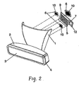
- FIG. 2 is another similar configuration that can be used within the scope of the present invention.
- This configuration may include, for instance: placing the wireless cellular antennas 6 inside the support of the mirror structure 1 around the main radio broadcast space-filling antenna 9; integrating two of the wireless cellular services into a standard dual-band antenna and placing it either inside the mirror housing 2 or mirror support 1; removing at least one of the antenna components for the antenna system in case one or more of the services is not required for a particular car model or car family; or redesigning a circularly polarized satellite antenna 7 for other frequencies and satellite applications that GPS (such as for instance Iridium, GlobalStar or other satellite phone or wireless data services) using conventional scaling techniques.
- GPS such as for instance Iridium, GlobalStar or other satellite phone or wireless data services
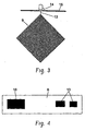
- Figure 3 describes an example of a space-filling antenna used for AM/FM signal reception.
- the conducting strip 9 defines a space-filling curve.
- the conducting strip 9 can, for instance, be printed using standard techniques on a low cost thin dielectric material such as glass fiber or polyester, which acts as a support for the antenna.
- this configuration is fed with a two conductor structure, such as a coaxial cable, with one of the conductors 13 connected to the conducting strip 13 of the space-filling antenna and the other conductor 14 connected to the metallic structure of the car 15, acting as ground counterpoise.
- the other side of the conducting strip 9 can be left without any connection, or can be connected to a specific load or to the same vehicle structure 15 to modify its impedance matching features, while keeping the same essential space-filling structure.
- the antenna is placed in the rearview mirror support 1 parallel to the windshield to assure an orientation close to vertical. Since this antenna is small compared to the operating wavelength, the radiation pattern observes a maximum radiation in the plane perpendicular to the antenna orientation, the horizontal plane in this case, which yields an optimum coverage for receiving terrestrial radio broadcast signals.
- Figure 4 describes another preferred embodiment where the set of miniature antennas for cellular signals, such as GSM 900, GSM 1800, UMTS and other equivalent systems, are distributed onto a common conducting ground counterpoise 8.
- the size and shape of the conducting sheet 10 is designed using standard well-known techniques to ensure a good impedance matching within the desired band.
- Each conducting sheet 10 presents a dimension lower than a quarter-wavelength of the operational frequency. This notable size reduction is due to the presence of a conducting strip between the conducting sheet 10 and the ground counterpoise 8.
- This configuration is fed by means of a vertical conducting pin coupled either by direct ohmic contact or by capacitive coupling to the conducting sheet 10.
- the radiation pattern of such antenna is similar to the radiation pattern of a conventional patch antenna presenting a major wide open lobe in the direction perpendicular to the conducting sheet 10, the horizontal plane in this case. Also, due to the reduced dimensions of the ground plane 8, radiation occurs in the opposite direction, assuring a fairly omnidirectional pattern. It is clear to those skilled in the art, that the relative position of the antenna is not important and can be changed without affecting the essence of the present invention.
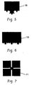
- Figure 5 is an improvement of any of the preceding examples that can be obtained by shaping at least a part of the perimeter of said conducting sheet 10 with a space-filling curve.
- the improvement of the perimeter length using a space-filling perimeter reduces the total size of the conducting sheet 10.
- Other space-filling curves besides the one displayed in Figure 5 can be used to increase the perimeter length.
- An important advantage of using a space-filling perimeter is that the resonant frequency is changed, while the rest of the antenna parameters (such as the radiation pattern or the antenna gain) are kept practically the same, which allows a size reduction (together with a cost and weight reduction) with respect to the previous example.
- Figures 7 to 10 presents several examples for a further miniaturization of the satellite antenna 7.
- the perimeter of the patch which characterizes the microstrip antenna is advantageously shaped by a space-filling curve.
- Figure 7 presents an example for a GPS antenna, characterized by its space-filling perimeter constructed with 20 segments.
- the shape can also be seen as a multilevel structure formed by 5 coupled squares. Except for the conducting sheet 11 shaping the patch, the antenna design remains similar to a conventional patch rectangular antenna.
- the circular polarization can be obtained either by a two-feeder scheme or by perturbing the perimeter of the superior conducting sheet 11 of the antenna, using the same conventional technique as a rectangular conducting sheet 11.
- the antenna also includes a low-noise high-gain pre-amplifier 12, mounted on a microstrip circuit alongside a microstrip GPS antenna, such that both the antenna and the circuit share the same conducting ground plane.
- the antenna is placed in the mirror base support 1 in a substantially horizontal position to ensure a broad, almost hemispherical coverage for the multiple satellite link.
- FIG. 8 Another example is presented in Figure 8.
- a similar space filling scheme as the one applied in the preceding example is used at the corners of each of the four squares.
- the size reduction of such antenna is beyond 59%, decreasing the antenna cost due to the area reduction of the high permittivity dielectric material supporting the microstrip antenna configuration.
- the radiation pattern of such antenna is kept in the same basic shape as a conventional microstrip antenna, ensuring an almost hemispherical coverage in the upper semi-space.
- one space-filling antenna is characterized by a conducting strip 9 composed by at least two-hundred segments. Said segments form a substantially right angle with each adjacent segment, and are smaller than a hundredth of the free-space operating central wavelength.
- This antenna is suitable for radio broadcast signal reception, such as AM and FM or DAB bands.
- the conducting strip 9 can be supported by any class of low loss dielectric materials including flexible or transparent boards.
- the system is completed by other space-filling antennas, with a conducting strip 9 that also defining a space-filling curve, although the number of segments is made smaller with respect to the previous one.
- These other space-filling antennas are designed transmission and reception using GSM 900, GSM 1800, UMTS or other equivalent cellular systems.
- a first conductor of a two-conductor input transmission line is connected to each conducting strip 9, while the second conductor is connected to the conducting structure of the vehicle, said conducting structure acting as the metallic counterpoise of the monopole configuration.
- these antennas observe a similar radiation pattern to that of a conventional elemental monopole, i.e. a substantially omnidirectional pattern on the horizontal plane.
- the position inside the mirror base support 1 offers an advantageous wide open visibility, assuring a correct reception from virtually any azimuthal direction.
- the same innovative space-filling shapes disclosed in the present invention can be advantageously used in any diversity techniques (such as space of polarization diversity) in order to compensate for signal fading due to a multipath propagation environment.
- the small size of said space-filling antennas allows an easy integration of the antenna in multiple parts of the motor vehicle, for instance, the rear brake-light housing mounted upon the rear window, or the dark sun-protection band that frames windows in a broad range of car models. Any of these configurations are compatible with the preferred embodiments shown in the present invention and share with them the same essential innovative aspect.
- FIG. 12 An alternative position for a GPS antenna 7 is presented in Figure 12.
- the GPS antenna 7 is placed in an external rearview mirror housing 16, in a substantially horizontal position. Placed in the top part of the housing 16, no obstacle blocks the vertical visibility of the antenna. The presence of metallic pieces of the car bodywork near the antenna does not affect the good reception of GPS signals, even if some signals are reflected.
- the right circular polarization of the GPS antenna cancels all other signals received at the same frequency with different polarizations. In particular, reflected satellite signals suffer from a strong polarization change and therefore do not interfere with the circularly polarized directly incoming signals.
- a low-noise amplifier is optionally mounted on the microstrip circuit alongside the microstrip GPS antenna such that both the antenna and the circuit share the same conducting ground plane.
- Figure 13 describes another example used for AM/FM reception.
- the conducting strip 9 describes another space-filling curve.
- This configuration is also fed with a two conductor structure, such as a coaxial cable, with one of the conductors 13 connected to the conducting strip 13 of the space-filling antenna and the other conductor 14 connected to the metallic structure of the car 15 and acting as a ground counterpoise.
- the other side of the conducting strip 9 can be left without any connection or can be connected to a specific load or to the same vehicle structure 15 to modify its impedance matching features, yet keeping the same essential space-filling structure.
- the antenna is placed in the rearview mirror support 1 parallel to the windshield to assure an orientation close to vertical. Since this antenna is small compared to the operating wavelength, the radiation pattern observes a maximum radiation in the plane perpendicular to the antenna orientation, in the horizontal plane in this case, which yields an optimum coverage for receiving terrestrial radio broadcast signals.
- FIGS 14-24 illustrate several alternative space-filling antenna structures for use in an antenna system for a motor vehicle.
- Each of the antenna structures illustrated in Figures 14-24 may, for example, be substituted for any of the space-filling antennas 5, 9, described above.
- each of the antenna structures illustrated in Figures 14-24 may alternatively be supported by a dielectric substrate(s), similar to the space-filling antenna 5 described above with reference to Figure 1.
- Figure 14 illustrates a cascaded space-filling antenna structure 20 for use in an antenna system for a motor vehicle.
- the space-filling antenna 20 includes four cascaded sections 21, 22, 23, 24 that each define a space-filling curve, and that collectively define a rectangular-shaped radiating arm. More specifically, each of the four cascaded sections 21, 22, 23, 24 of the space-filling antenna 20 include a conductor that extends in a continuous space-filling curve.
- the four sections 21, 22, 23, 24 are cascaded together, forming a continuous conductive path from a first antenna endpoint 25 to a second antenna endpoint 26.
- the first antenna endpoint 25 may, for example, function as a feeding point for the antenna 20, and the second antenna endpoint 26 may, for example, function as a grounding point for the antenna 20.
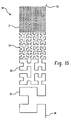
- FIG 15 illustrates one alternative cascaded space-filling antenna structure 30 for use in an antenna system for a motor vehicle.
- This embodiment 30 is similar to the cascaded antenna structure 20 of Figure 14, except that each cascaded section 31, 32, 33, 34 defines a space-filling curve of a different length and having a different number of segments.
- the four sections 31, 32, 33, 34 of this antenna structure 30 are cascaded together, forming a continuous conductive path from a first antenna endpoint 35 to a second antenna endpoint 36.
- the first antenna endpoint 35 may, for example, function as a feeding point for the antenna 30, and the second antenna endpoint 36 may, for example, function as a grounding point for the antenna 30.
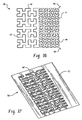
- FIG 16 illustrates another alternative cascaded space-filling antenna structure 40 for use in an antenna system for a motor vehicle.
- the space-filling antenna 40 includes four cascaded sections 41, 42, 43, 44 that each define a space-filling curve, and that collectively define a square-shaped radiating arm. More specifically, each of the four cascaded sections 41, 42, 43, 44 include a conductor that extends in a continuous space-filling curve.
- the two cascaded sections 41, 44 illustrated on the right half of the antenna structure each define a space-filling curve having a first length and a first number of segments, and the two cascaded sections 42, 43 illustrated on the left half of the antenna structure each define a space-filling curve having a second length and a second number of segments.
- the four sections 41, 42, 43, 44 are cascaded together at their endpoints, forming a continuous conductive path from a first antenna endpoint 45 to a second antenna endpoint 46.
- the first antenna endpoint 45 may, for example, function as a feeding point for the antenna 40
- the second antenna endpoint 46 may, for example, function as a grounding point for the antenna 40.
- FIG 17 illustrates a space-filling slot antenna 50 for use in an antenna system for a motor vehicle.
- This antenna embodiment 50 includes a conductive plate 51 and a space-filling curve 52 that is defined by a slot through the surface of the conductive plate 51.
- the antenna 50 may, for example, include an antenna feeding point on the surface of the conductive plate 51.
- FIG 18 illustrates a cascaded space-filling antenna structure 60 having a reactive element (z) 61 coupled in series with the antenna feeding point 36.
- This antenna embodiment 60 is similar to the cascaded antenna 30 of Figure 15, with the exception of the reactive element 61.
- the reactive element 61 is preferably an inductor, and may be selected to tune the impedance of the antenna 60.
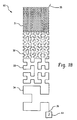
- FIG 19 illustrates a cascaded space-filling antenna structure 70 having a top-loading element 73.
- This example 70 is similar to the cascaded antenna 20 of Figure 14, except that two of the cascaded sections are replaced by the top-loading element 73.
- the space-filling antenna 70 includes two cascaded sections 71, 72 and the top-loading element 73. Both of the cascaded sections 71, 72 include a conductor that defines a space-filling curve. More particularly, the two cascaded sections 71, 72 are cascaded together, forming a continuous conductive path from a first endpoint 74 to a second endpoint 75. The second endpoint 75 is coupled to the top-loading element 73, which is a rectangular-shaped conductive plate.
- the first endpoint 74 may, for example, function as a feeding point for the antenna 70.
- the top-loading portion 73 may, for example, include a grounding point for the antenna 70.
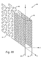
- Figure 20 is a three-dimensional view of a cascaded space-filling antenna structure 80 having two vertically stacked radiating arms 81, 82. Also shown are x, y, and z axes to help illustrate the orientation of the antenna 80.
- Each radiating arm 81, 82 is similar to the cascaded antenna structure 40 of Figure 16. More particularly, a first radiating arm 81 includes four cascaded sections that each define a space-filling curve in the xy plane. Similarly, a second radiating arm 82 includes four cascades sections that each define a space-filling curve parallel to the xy plane.
- the first radiating arm 81 forms a continuous conductive path from an antenna feeding point 83 to a common conductor 85
- the second radiating arm 82 forms a continuous conductive path from the common conductor 85 to a grounding point 84. That is, the antenna 80 forms one continuous conductive path from the antenna feeding point 83 on the first radiating arm 81 to the grounding point 84 on the second radiating arm 82.
- the two radiating arms 83, 84 may be attached to opposite sides of a dielectric substrate, such as a printed circuit board.
- Figure 21 illustrates another example cascaded space-filling antenna structure 90 for use in an antenna system for a motor vehicle.
- the space-filling antenna 90 includes two cascaded sections 91, 92 that each define a space-filling curve.
- the cascaded sections 91, 92 both include a conductor that extends in a continuous space-filling curve, wherein the space-filling curve defined by one section 91 is a mirror image of the space-filling curve defined by the other section 92.
- a first section 92 of the space-filling antenna 90 extends in a continuous space-filling curve from a feeding point 93 to a common point 94, and a second section 92 of the space-filling antenna 90 extends in a continuous space-filling curve from the common point 94 to a grounding point 95.
- FIG 22 is a three-dimensional view of a cascaded space-filling antenna structure 110 having a plurality of parallel-fed vertically stacked radiating arms 111-114.
- This embodiment 110 is similar to the antenna structure 80 of Figure 20, except that this antenna 110 includes a common feeding point 115 and a plurality of radiating arms 111-114.
- Each radiating arm 111-114 defines four cascaded space-filling curves, with each of the radiating arms 111-114 lying in a parallel plane.
- the cascaded space-filling curves defined by each parallel radiating arm 111-114 extend continuously within their respective planes from a common feeding point 115 to a common conductor 116.
- the common conductor 116 may, for example, be coupled to a ground potential.
- the radiating arms 111- 114 may be separated by a dielectric substrate, such as layers in a multi-layer printed circuit board.
- Figure 23 is a three-dimensional view of a cascaded space-filling antenna structure 120 having two parallel-fed radiating arms.
- the two radiating arms each include two cascaded sections 121-124, with each of the four cascading sections 121-124 being similar to the cascaded space-filling antenna structure 40 of Figure 16.
- a first radiating arm 121, 122 extends continuously, defining a plurality of space-filling curves, from a common feeding point 125 to a first endpoint 126.
- a second radiating arm 123, 124 extends continuously, defining a plurality of space-filling curves, from the common feeding point 125 to a second endpoint 127.
- the first and second endpoints 126, 127 may be coupled to a ground potential, providing two parallel paths between the common feeding point 125 and ground.
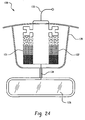
- FIG 24 illustrates another embodiment of a cascaded space-filling antenna structure 130 mounted within the housing of a rear view mirror 135.
- This antenna structure 130 includes two parallel-fed radiating arms 131, 132, each of which defines four cascaded space-filling curves, similar to the cascaded antenna structure 30 of Figure 15. More particularly, both radiating arms 131, 132 extends continuously, defining a plurality of space-filling curves, from a common feeding point 133 to a common loading or grounding point 134. That is, the radiating arms 131, 132 provide two parallel conductive paths between the common feeding point 133 and the common loading or grounding point 134.
- the cascaded space-filling antenna structure 130 may be mounted, for example, within the housing 135 of the rear view mirror in an automobile.
- the loading point 134 of the antenna 130 may, for example, be coupled to the metallic surface 136 of the mirror, or to some other conducting load.
- the feeding point 133 may be coupled to circuitry within the automobile to provide an antenna for AM/FM signal reception, DAB/AM signal reception, cellular or GPS service, or other wireless applications.
- Figure 25 is a three-dimensional view of a cascaded space-filling antenna structure 100 having an active radiating arm 101 and a parasitic radiating arm 102.
- This embodiment 100 is similar to the antenna structure show in Figure 20, except that this embodiment 100 does not include a common conductor 85 connecting the two radiating arms. Rather, in this embodiment 100, one radiating arm 101 includes a feeding point 103 for the antenna 100, and the other radiating arm 102 is coupled to a ground potential at a grounding point 104.
- the active and passive radiating arms 101, 102 are separated by a distance (d) that is selected to enable electromagnetic coupling between the two antenna portions 101, 102.
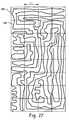
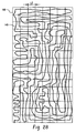
- Figures 26-29 illustrate an example two-dimensional antenna geometry 140 referred to as a grid dimension curve.
- An antenna structure defining a grid dimension curve may be substituted for any of the space-filling antenna structures described above with reference to Figures 1-25.
- the grid dimension of a curve may be calculated as follows.
- a first grid having square cells of length L1 is positioned over the geometry of the curve, such that the grid completely covers the curve.
- the number of cells (N1) in the first grid that enclose at least a portion of the curve are counted.
- a second grid having square cells of length L2 is similarly positioned to completely cover the geometry of the curve, and the number of cells (N2) in the second grid that enclose at least a portion of the curve are counted.
- the first and second grids should be positioned within a minimum rectangular area enclosing the curve, such that no entire row or column on the perimeter of one of the grids fails to enclose at least a portion of the curve.
- the first grid should include at least twenty-five cells, and the second grid should include four times the number of cells as the first grid.
- the length (L2) of each square cell in the second grid should be one-half the length (L1) of each square cell in the first grid.
- grid dimension curve is used to describe a curve geometry having a grid dimension that is greater than one (1).
- the larger the grid dimension the higher the degree of miniaturization that may be achieved by the grid dimension curve in terms of an antenna operating at a specific frequency or wavelength.
- a grid dimension curve may, in some cases, also meet the requirements of a space-filling curve, as defined above. Therefore, for the purposes of this application a space-filling curve is one type of grid dimension curve.
- Figure 26 shows an example two-dimensional antenna 140 forming a grid dimension curve with a grid dimension of approximately two (2).
- Figure 27 shows the antenna 140 of Figure 26 enclosed in a first grid 150 having thirty-two (32) square cells, each with a length L1.
- Figure 28 shows the same antenna 140 enclosed in a second grid 160 having one hundred twenty-eight (128) square cells, each with a length L2.
- An examination of Figures 27 and 28 reveal that at least a portion of the antenna 140 is enclosed within every square cell in both the first and second grids 150, 160.
- the value of N1 in the above grid dimension (Dg) equation is thirty-two (32) (i.e., the total number of cells in the first grid 150), and the value of N2 is one hundred twenty-eight (128) (i.e., the total number of cells in the second grid 160).
- the number of square cells may be increased up to a maximum amount.
- the maximum number of cells in a grid is dependant upon the resolution of the curve. As the number of cells approaches the maximum, the grid dimension calculation becomes more accurate. If a grid having more than the maximum number of cells is selected, however, then the accuracy of the grid dimension calculation begins to decrease.
- the maximum number of cells in a grid is one thousand (1000).
- Figure 29 shows the same antenna 140 enclosed in a third grid 170 with five hundred twelve (512) square cells, each having a length L3.
- the length (L3) of the cells in the third grid 170 is one half the length (L2) of the cells in the second grid 160, shown in Figure 28.
- N for the second grid 160 is one hundred twenty-eight (128).
- An examination of Figure 29, however, reveals that the antenna 140 is enclosed within only five hundred nine (509) of the five hundred twelve (512) cells of the third grid 170. Therefore, the value of N for the third grid 170 is five hundred nine (509).
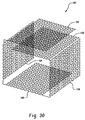
- Figs. 30 and 31 illustrate two additional antenna structures 180, 200 for use in an antenna system for a motor vehicle. More particularly, Figs. 30 and 31 illustrate two non-planar antenna examples 180, 200. Either of these antenna structures 180, 200 may, for example, be substituted for any of the space-filling antennas 5, 9, described above with reference to Figs. 1-13.
- Fig. 30 illustrates an example non-planar antenna structure 180 having a plurality of cascaded folded sections 182-190.
- the folded sections 182-190 of the antenna 180 each define a space-filling curve, and are cascaded such that the antenna 180 extends in one continuous conductive path between two endpoints.
- the sections 182-190 of the antenna structure 180 are folded such that each section 182-190 lies in a plane that is perpendicular to an adjacent section, and two end sections 182, 190 lie in parallel planes.
- Fig. 31 illustrates another example non-planar antenna structure 200 having a plurality of cascaded folded sections 202-210.
- This example 200 is similar to the antenna 180 shown in Fig. 30, except that each of the folded sections 202-210 shown in Fig. 31 form space-filling curves having a different length and a different number of connected segments.
- the cascaded sections 182-190 and 202-210 of the antennas 180, 200 shown in Figs. 30 and 31 may also define grid dimension curves, as described above with reference to Figs. 26-29.
- the antenna structures 180, 200 may alternatively be attached to a flexible substrate material, such as a flex-film printed circuit board.
- the folded sections 182-190 and 202-210 of the non-planar antennas 180, 200 may, for example, be wrapped around inside the base of a rear-view mirror in a motor vehicle, but could also be integrated into other physical components of the motor vehicle.
Landscapes
- Engineering & Computer Science (AREA)
- Remote Sensing (AREA)
- Details Of Aerials (AREA)
- Support Of Aerials (AREA)
- Variable-Direction Aerials And Aerial Arrays (AREA)
- Fittings On The Vehicle Exterior For Carrying Loads, And Devices For Holding Or Mounting Articles (AREA)
Claims (25)
- Radio-, Mobilfunk-Telefonie- oder Satelliten-Signal-Antenne (30) zur Integration innerhalb einer physikalischen Komponente eines Kraftfahrzeuges, wobei die Antenne einen abstrahlenden Arm und ferner einen Einspeisepunkt (35) zum Verbinden der Antenne mit einem Empfänger in dem Kraftfahrzeug umfasst, wobei der abstrahlende Arm eine Mehrzahl von kaskadierten Abschnitten (32, 32, 33, 34) umfasst, wobei jeder kaskadierte Abschnitt (31, 32, 33, 34) eine raumfüllende Kurve beschreibt, welche aus zumindest zehn Segmenten gebildet wird, wobei jeder dieser einen Winkel mit jedem benachbarten Segment bildet,
dadurch gekennzeichnet, dass
die raumfüllenden Kurven der kaskadierten Abschnitte (31, 32, 33, 34) unterschiedliche Iterationen derselben Kurve in einem unterschiedlichen Maßstab sind und eine unterschiedliche Länge aufweisen und eine unterschiedliche Anzahl von Segmenten aufweisen. - Mehrdienst-Antennen-System (30, 40, 50, 60) für ein Kraftfahrzeug, umfassend eine Mehrzahl von Antennen-Strukturen, welche innerhalb einer physikalischen Komponente des Kraftfahrzeuges integriert sind, wobei die Mehrzahl von Antennen-Strukturen eine Radio-Antenne gemäß Anspruch 1 und zumindest eine Antenne von einer Mobilfunk-Telefonie-Antenne oder einer Satelliten-Signal-Antenne beinhaltet.
- Antennen-System (30, 40, 50, 60) nach Anspruch 2, wobei die Radio-Antenne an einem dielektrischen Substrat befestigt ist.
- Antennen-System (30, 40, 50, 60) nach einem der Ansprüche 2 oder 3, wobei das Antennen-System (30, 40, 50, 60) in einer Innen-Rückspiegel-Anordnung integriert ist.
- Antennen-System (30, 40, 50, 60) nach Anspruch 4, wobei die Radio-Antenne innerhalb einer Unterlagen-Halterung der Rückspiegel-Anordnung integriert ist.
- Antennen-System (30, 40, 50, 60) nach einem der Ansprüche 2 bis 5, wobei das Antennen-System (30, 40, 50, 60) in einer Außen-Licht-Anordnung integriert ist.
- Antennen-System (30, 40, 50, 60) nach Anspruch 6, wobei das Antennen-System (30, 40, 50, 60) in einer Rück-Bremslicht-Anordnung integriert ist.
- Antennen-System (30, 40, 50, 60) nach einem der Ansprüche 2 bis 7, wobei der Einspeisepunkt der Radio-Antenne ein Teil des abstrahlenden Armes ist.
- Antennen-System (30, 40, 50, 60) nach einem der Ansprüche 2 bis 8, wobei die Radio-Antenne einen Erdungs-Punkt zum Verbinden der Radio-Antenne mit einem Masse-Gegengewicht umfasst.
- Antennen-System (30, 40, 50, 60) nach einem der Ansprüche 2 bis 9, wobei die Radio-Antenne einen Last-Punkt (75) zum Verbinden der Radio-Antenne mit einer leitenden Last (73) umfasst.
- Antennen-System (30, 40, 50, 60) nach Anspruch 10, wobei die leitende Last ein metallischer Teil einer Rückspiegel-Anordnung ist.
- Antennen-System (30, 40, 50, 60) nach einem der Ansprüche 2 bis 11, wobei die Radio-Antenne konfiguriert ist, als eine FM-Band-Antenne zu arbeiten.
- Antennen-System (30, 40, 50, 60) nach einem der Ansprüche 2 bis 12, wobei die Radio-Antenne konfiguriert ist, als eine AM-Band-Antenne zu arbeiten.
- Antennen-System (30, 40, 50, 60) nach einem der Ansprüche 2 bis 13, wobei die Radio-Antenne konfiguriert ist, als DAB-Band-Antenne zu arbeiten.
- Antennen-System (30, 40, 50, 60) nach einem der Ansprüche 2 bis 14, wobei die Mobilfunk-Telefonie-Antenne eine erste leitende Platte und eine zweite leitende Platte, welche mit der ersten leitenden Platte gekoppelt ist, beinhaltet, wobei die zweite leitende Platte als ein Masse-Gegengewicht für die Mobilfunk-Telefonie-Antenne arbeitet.
- Antennen-System (30, 40, 50, 60) nach Anspruch 15, wobei die erste leitende Platte eine Länge aufweist, die kleiner als ein Viertel der Betriebs-Wellenlänge der Mobilfunk-Telefonie-Antenne im freien Raum ist.
- Antennen-System (30, 40, 50, 60) nach einem der Ansprüche 15 bis 16, wobei die erste leitende Platte in einer ersten Ebene liegt und die zweite leitende Platte in einer zweiten Ebene liegt, wobei die erste Ebene parallel zu der zweiten Ebene ist.
- Antennen-System (30, 40, 50, 60) nach einem der Ansprüche 15 bis 17, wobei die Mobilfunk-Telefonie-Antenne einen leitende Anschluss zum Koppeln der ersten leitende Platte mit einer Mobilfunk-Transceiver-Schaltung in dem Kraftfahrzeug beinhaltet.
- Antennen-System (30, 40, 50, 60) nach Anspruch 18, wobei der leitende Anschluss (35) durch einen direkten ohmschen Kontakt mit der ersten leitenden Platte gekoppelt wird.
- Antennen-System (30, 40, 50, 60) nach Anspruch 18, wobei der leitende Anschluss (35) mit der ersten leitenden Platte durch kapazitive Kopplung gekoppelt wird.
- Antennen-System (30, 40, 50, 60) nach einem der Ansprüche 2 bis 20, wobei die Mobilfunk-Telefonie-Antenne konfiguriert ist, Mobilfunk-Telefonie-Signale in einem Mobilfunk-Band ausgewählt aus der Gruppe GSM 900, GSM 1800, UMTS, WCDMA, CDMA, PCS 1900, KPCS, AMPS, TACS und ETACS zu senden und zu empfangen.
- Antennen-System (30, 40, 50, 60) nach einem der Ansprüche 2 bis 21, wobei das Satelliten-Signal-Antenne eine Mikrostreifen-Antenne mit zirkularer Polarisation bildet, wobei die Satelliten-Signal-Antenne eine erste leitende Platte und eine zweite leitende Platte aufweist, wobei die erste leitende Platte von der zweiten leitenden Platte durch ein dielektrisches Material separiert wird.
- Antennen-System (30, 40, 50, 60) nach Anspruch 22, ferner umfassend:einen low-noise, high-gain Verstärker, welcher zwischen der Satelliten-Signal-Antenne und dem Satelliten-Signal-Empfänger-Schaltung in dem Kraftfahrzeug verbunden ist.
- Antennen-System (30, 40, 50, 60) nach einem der Ansprüche 22 bis 23, wobei die Satelliten-Signal-Antenne konfiguriert ist, Global-Positioning-Satellite-Signale (GPS) zu empfangen.
- Antennen-System (30, 40, 50, 60) nach einem der Ansprüche 22 bis 24, wobei die Satelliten-Signal-Antenne in einem Außen-Rückspiegel-Gehäuse integriert ist.
Applications Claiming Priority (2)
| Application Number | Priority Date | Filing Date | Title |
|---|---|---|---|
| US10/422,578 US7511675B2 (en) | 2000-10-26 | 2003-04-24 | Antenna system for a motor vehicle |
| PCT/EP2004/004333 WO2004095635A1 (en) | 2003-04-24 | 2004-04-23 | Antenna system for a motor vehicle |
Publications (2)
| Publication Number | Publication Date |
|---|---|
| EP1616368A1 EP1616368A1 (de) | 2006-01-18 |
| EP1616368B1 true EP1616368B1 (de) | 2007-11-14 |
Family
ID=33309589
Family Applications (1)
| Application Number | Title | Priority Date | Filing Date |
|---|---|---|---|
| EP04729070A Expired - Lifetime EP1616368B1 (de) | 2003-04-24 | 2004-04-23 | Antennensystem für ein kraftfahrzeug |
Country Status (8)
| Country | Link |
|---|---|
| US (1) | US7511675B2 (de) |
| EP (1) | EP1616368B1 (de) |
| JP (1) | JP4741466B2 (de) |
| KR (1) | KR100821453B1 (de) |
| CN (1) | CN1816943B (de) |
| AT (1) | ATE378701T1 (de) |
| DE (1) | DE602004010089T2 (de) |
| WO (1) | WO2004095635A1 (de) |
Cited By (2)
| Publication number | Priority date | Publication date | Assignee | Title |
|---|---|---|---|---|
| EP3383005A1 (de) | 2017-03-30 | 2018-10-03 | RIEDEL Communications International GmbH | Netzwerkgerät für ein intercom-netzwerk |
| DE102017116273A1 (de) | 2017-03-30 | 2018-10-04 | Riedel Communications International GmbH | Netzwerkgerät für ein Intercom-Netzwerk |
Families Citing this family (73)
| Publication number | Priority date | Publication date | Assignee | Title |
|---|---|---|---|---|
| EP1592083B1 (de) | 2000-01-19 | 2013-04-03 | Fractus, S.A. | raumfüllende miniaturantennen |
| CN100382385C (zh) | 2001-10-16 | 2008-04-16 | 弗拉克托斯股份有限公司 | 加载天线 |
| US9755314B2 (en) | 2001-10-16 | 2017-09-05 | Fractus S.A. | Loaded antenna |
| JP2005531177A (ja) * | 2002-06-25 | 2005-10-13 | フラクトゥス・ソシエダッド・アノニマ | ハンドヘルド端末装置用マルチバンドアンテナ |
| EP1563570A1 (de) | 2002-11-07 | 2005-08-17 | Fractus, S.A. | Integriertes schaltungsgehäuse mit miniaturantenne |
| ATE545173T1 (de) | 2002-12-22 | 2012-02-15 | Fractus Sa | Mehrband-monopolantenne für ein mobilfunkgerät |
| AU2003215572A1 (en) | 2003-02-19 | 2004-09-09 | Fractus S.A. | Miniature antenna having a volumetric structure |
| EP1709704A2 (de) * | 2004-01-30 | 2006-10-11 | Fractus, S.A. | Mehrband-monopolantennen für mobilkommunikationsgeräte |
| WO2005086933A2 (en) * | 2004-03-09 | 2005-09-22 | Procon, Inc. | Combination service request and satellite radio system |
| US7026997B2 (en) * | 2004-04-23 | 2006-04-11 | Nokia Corporation | Modified space-filling handset antenna for radio communication |
| KR100616545B1 (ko) * | 2004-05-04 | 2006-08-29 | 삼성전기주식회사 | 이중 커플링 급전을 이용한 다중밴드용 적층형 칩 안테나 |
| ES2348546T3 (es) * | 2004-06-29 | 2010-12-09 | A3 - Advanced Automotive Antennas | Montaje de sistema de antenas multiservicio. |
| US7376446B2 (en) * | 2004-07-15 | 2008-05-20 | Nokia Siemens Networks Gmbh & Co. Kg | Mobile communications network with expanded carrier capacity and method of expanding base station carrier capacity |
| EP1771919A1 (de) * | 2004-07-23 | 2007-04-11 | Fractus, S.A. | Gekapselte antenne mit verringerter elektromagnetischer wechselwirkung mit elementen auf dem chip |
| US7924226B2 (en) * | 2004-09-27 | 2011-04-12 | Fractus, S.A. | Tunable antenna |
| WO2006051113A1 (en) * | 2004-11-12 | 2006-05-18 | Fractus, S.A. | Antenna structure for a wireless device with a ground plane shaped as a loop |
| KR20070091160A (ko) * | 2004-12-09 | 2007-09-07 | 에이쓰리-어드밴스드 오토모티브 안테나스 | 자동차용 미니어처 안테나 |
| WO2006120250A2 (en) * | 2005-05-13 | 2006-11-16 | Fractus, S.A. | Antenna diversity system and slot antenna component |
| US20070052590A1 (en) * | 2005-08-23 | 2007-03-08 | Tze-Hsuan Chang | Miniatured microstrip antenna |
| US7425925B2 (en) * | 2006-02-27 | 2008-09-16 | Nissan Technical Center North America, Inc. | Vehicle security system |
| KR100808811B1 (ko) | 2006-04-13 | 2008-03-03 | (주)모토닉스 | 차량용 다중대역 안테나 |
| JP2007320339A (ja) * | 2006-05-30 | 2007-12-13 | Honda Motor Co Ltd | 車両用灯体 |
| US9007275B2 (en) | 2006-06-08 | 2015-04-14 | Fractus, S.A. | Distributed antenna system robust to human body loading effects |
| US8738103B2 (en) | 2006-07-18 | 2014-05-27 | Fractus, S.A. | Multiple-body-configuration multimedia and smartphone multifunction wireless devices |
| KR100787602B1 (ko) * | 2006-12-01 | 2007-12-21 | (주)하이게인텔레콤 | 자동차의 송수신용 통합안테나 모듈 |
| JP2008260430A (ja) * | 2007-04-12 | 2008-10-30 | Noba Denko Kk | 日射センサの取付構造 |
| KR100878706B1 (ko) * | 2007-04-16 | 2009-01-14 | 삼성탈레스 주식회사 | 다중공진 광대역 안테나 |
| US8405552B2 (en) * | 2007-04-16 | 2013-03-26 | Samsung Thales Co., Ltd. | Multi-resonant broadband antenna |
| DE112008001263B4 (de) | 2007-05-10 | 2022-07-07 | Advanced Automotive Antennas, S.L. | Fahrzeugspiegel-Antennenbaugruppe |
| USD588116S1 (en) * | 2007-09-06 | 2009-03-10 | Advanced Automotive Antennas, S.L. | Aerial |
| JP4871949B2 (ja) | 2007-12-20 | 2012-02-08 | 原田工業株式会社 | パッチアンテナ装置 |
| KR100939704B1 (ko) | 2008-01-03 | 2010-02-01 | (주) 모토텍 | 차량용 프랙탈 안테나 |
| JP4524318B2 (ja) * | 2008-05-27 | 2010-08-18 | 原田工業株式会社 | 車載用ノイズフィルタ |
| JP5114325B2 (ja) * | 2008-07-08 | 2013-01-09 | 原田工業株式会社 | 車両用ルーフマウントアンテナ装置 |
| US8203492B2 (en) | 2008-08-04 | 2012-06-19 | Fractus, S.A. | Antennaless wireless device |
| WO2010015364A2 (en) | 2008-08-04 | 2010-02-11 | Fractus, S.A. | Antennaless wireless device capable of operation in multiple frequency regions |
| US9065177B2 (en) | 2009-01-15 | 2015-06-23 | Broadcom Corporation | Three-dimensional antenna structure |
| US8570229B2 (en) | 2009-01-15 | 2013-10-29 | Broadcom Corporation | Multiple antenna high isolation apparatus and application thereof |
| US8570222B2 (en) | 2009-01-15 | 2013-10-29 | Broadcom Corporation | Antenna structures and applications thereof |
| US8045592B2 (en) * | 2009-03-04 | 2011-10-25 | Laird Technologies, Inc. | Multiple antenna multiplexers, demultiplexers and antenna assemblies |
| US20120057588A1 (en) * | 2009-03-04 | 2012-03-08 | Laird Technologies, Inc. | Multiple antenna multiplexers, demultiplexers and antenna assemblies |
| KR101066407B1 (ko) * | 2009-03-19 | 2011-09-23 | 주식회사 에이스테크놀로지 | 차량용 안테나 |
| KR101080889B1 (ko) * | 2009-04-02 | 2011-11-09 | 주식회사 에이스테크놀로지 | 차량용 안테나 장치 |
| JP4832549B2 (ja) * | 2009-04-30 | 2011-12-07 | 原田工業株式会社 | 空間充填曲線を用いる車両用アンテナ装置 |
| GB2470205B (en) * | 2009-05-13 | 2013-05-22 | Antenova Ltd | Branched multiport antennas |
| JP4955094B2 (ja) * | 2009-11-02 | 2012-06-20 | 原田工業株式会社 | パッチアンテナ |
| EP2339693A1 (de) * | 2009-12-18 | 2011-06-29 | Broadcom Corporation | Dreidimensionale Antennenstruktur |
| WO2011095330A1 (en) | 2010-02-02 | 2011-08-11 | Fractus, S.A. | Antennaless wireless device comprising one or more bodies |
| CN103155276B (zh) | 2010-08-03 | 2015-11-25 | 弗拉克托斯天线股份有限公司 | 能够进行多带mimo操作的无线装置 |
| KR101773472B1 (ko) * | 2010-08-10 | 2017-09-01 | 삼성전자주식회사 | 유전 자성체로 이루어지는 소자 캐리어를 갖는 안테나 장치 및 그 제조 방법 |
| CN102412440A (zh) * | 2010-09-20 | 2012-04-11 | 云南银河之星科技有限公司 | 一种超宽带天线 |
| DE102011013667A1 (de) * | 2010-12-20 | 2012-06-21 | Continental Automotive Gmbh | Bordinformationssystem mit Antenne zum Empfang satellitenbasierter Geopositionsdaten |
| US8816917B2 (en) | 2011-01-12 | 2014-08-26 | Harada Industry Co., Ltd. | Antenna device |
| JP5274597B2 (ja) | 2011-02-15 | 2013-08-28 | 原田工業株式会社 | 車両用ポールアンテナ |
| US9203163B2 (en) * | 2011-02-25 | 2015-12-01 | Harada Industry Of America, Inc. | Antenna assembly |
| JP5654917B2 (ja) | 2011-03-24 | 2015-01-14 | 原田工業株式会社 | アンテナ装置 |
| GB201120328D0 (en) * | 2011-11-24 | 2012-01-04 | Renesas Mobile Corp | Wireless communication apparatus and method |
| USD726696S1 (en) | 2012-09-12 | 2015-04-14 | Harada Industry Co., Ltd. | Vehicle antenna |
| DE102013006056A1 (de) * | 2013-04-08 | 2014-10-09 | Audi Ag | Anbauteil für ein Kraftfahrzeug und zugehöriges Kraftfahrzeug |
| JP5681747B2 (ja) * | 2013-04-22 | 2015-03-11 | 原田工業株式会社 | 車載アンテナ装置 |
| US9728844B2 (en) * | 2013-07-31 | 2017-08-08 | Sensor Systems, Inc. | High-gain digitally tuned antenna system with modified swept-back fractal (MSBF) blade |
| JP6547311B2 (ja) * | 2015-01-30 | 2019-07-24 | Agc株式会社 | Mimoアンテナ及びmimoアンテナ配置構造 |
| KR101827706B1 (ko) * | 2016-09-20 | 2018-02-12 | 현대자동차주식회사 | 차량 및 차량의 제어 방법 |
| CN108242587B (zh) * | 2016-12-23 | 2020-03-10 | 华为技术有限公司 | 天线、照明系统及通信系统 |
| CN110870133B (zh) | 2017-07-06 | 2023-02-17 | 伊格尼恩有限公司 | 用于无线通信的模块化多级天线系统和组件 |
| US10673122B2 (en) * | 2017-10-20 | 2020-06-02 | Gentex Corporation | Vehicle communication module with improved transmission |
| WO2019090049A1 (en) * | 2017-11-03 | 2019-05-09 | Antenum, Llc | Smart antenna for in-vehicle applications that can be integrated with tcu and other electronics |
| US11005167B2 (en) | 2017-11-03 | 2021-05-11 | Antenum Llc | Low profile antenna-conformal one dimensional |
| US11693111B2 (en) * | 2018-07-06 | 2023-07-04 | Sony Corporation | Distance measurement apparatus and windshield |
| US10965033B2 (en) | 2018-11-14 | 2021-03-30 | Taoglas Group Holdings Limited | Adaptive-spacing antenna |
| US20200177221A1 (en) * | 2018-12-04 | 2020-06-04 | The United States Of America As Represented By Secretary Of The Navy | Submerged Maritime Tag Track and Locate Device and System |
| JP7455492B2 (ja) * | 2022-02-02 | 2024-03-26 | ダイハツ工業株式会社 | 車載通信装置 |
| WO2025203116A1 (en) * | 2024-03-29 | 2025-10-02 | Eicher Motors Limited | Onboard antenna device for a vehicle |
Family Cites Families (209)
| Publication number | Priority date | Publication date | Assignee | Title |
|---|---|---|---|---|
| US2976534A (en) * | 1959-07-02 | 1961-03-21 | Kampinsky Abe | Circularly polarized antenna |
| US4471358A (en) * | 1963-04-01 | 1984-09-11 | Raytheon Company | Re-entry chaff dart |
| US3521284A (en) | 1968-01-12 | 1970-07-21 | John Paul Shelton Jr | Antenna with pattern directivity control |
| US3622890A (en) | 1968-01-31 | 1971-11-23 | Matsushita Electric Industrial Co Ltd | Folded integrated antenna and amplifier |
| US3599214A (en) * | 1969-03-10 | 1971-08-10 | New Tronics Corp | Automobile windshield antenna |
| US3683376A (en) * | 1970-10-12 | 1972-08-08 | Joseph J O Pronovost | Radar antenna mount |
| US3729740A (en) * | 1971-01-20 | 1973-04-24 | Sumitomo Electric Industries | Vehicle antenna for vehicular communication system using leaky coaxial cable |
| US3818490A (en) * | 1972-08-04 | 1974-06-18 | Westinghouse Electric Corp | Dual frequency array |
| ES443806A1 (es) * | 1974-12-25 | 1977-08-16 | Matsushita Electric Industrial Co Ltd | Perfeccionamientos introducidos en un aparato de antena paraun receptor de television o similar. |
| US3967276A (en) * | 1975-01-09 | 1976-06-29 | Beam Guidance Inc. | Antenna structures having reactance at free end |
| US3969730A (en) * | 1975-02-12 | 1976-07-13 | The United States Of America As Represented By The Secretary Of Transportation | Cross slot omnidirectional antenna |
| GB1481485A (en) * | 1975-05-29 | 1977-07-27 | Furukawa Electric Co Ltd | Ultra-high-frequency leaky coaxial cable |
| US4131893A (en) | 1977-04-01 | 1978-12-26 | Ball Corporation | Microstrip radiator with folded resonant cavity |
| US4141016A (en) * | 1977-04-25 | 1979-02-20 | Antenna, Incorporated | AM-FM-CB Disguised antenna system |
| JPS55147806U (de) | 1979-04-07 | 1980-10-24 | ||
| HU182355B (en) * | 1981-07-10 | 1983-12-28 | Budapesti Radiotechnikai Gyar | Aerial array for handy radio transceiver |
| DE3222584A1 (de) | 1982-06-16 | 1983-12-22 | Diehl GmbH & Co, 8500 Nürnberg | Dipol-anordnung in einer huelse |
| US4471493A (en) * | 1982-12-16 | 1984-09-11 | Gte Automatic Electric Inc. | Wireless telephone extension unit with self-contained dipole antenna |
| US4504834A (en) * | 1982-12-22 | 1985-03-12 | Motorola, Inc. | Coaxial dipole antenna with extended effective aperture |
| DE3302876A1 (de) * | 1983-01-28 | 1984-08-02 | Robert Bosch Gmbh, 7000 Stuttgart | Dipolantenne fuer tragbare funkgeraete |
| IT8321342U1 (it) | 1983-04-01 | 1984-10-01 | Icma Spa | Antenna per autoradio |
| US4584709A (en) * | 1983-07-06 | 1986-04-22 | Motorola, Inc. | Homotropic antenna system for portable radio |
| US4839660A (en) * | 1983-09-23 | 1989-06-13 | Orion Industries, Inc. | Cellular mobile communication antenna |
| DE3337941A1 (de) | 1983-10-19 | 1985-05-09 | Bayer Ag, 5090 Leverkusen | Passive radarreflektoren |
| US4571595A (en) * | 1983-12-05 | 1986-02-18 | Motorola, Inc. | Dual band transceiver antenna |
| US4816618A (en) * | 1983-12-29 | 1989-03-28 | University Of California | Microminiature coaxial cable and method of manufacture |
| US4623894A (en) | 1984-06-22 | 1986-11-18 | Hughes Aircraft Company | Interleaved waveguide and dipole dual band array antenna |
| US4647878A (en) * | 1984-11-14 | 1987-03-03 | Itt Corporation | Coaxial shielded directional microwave coupler |
| US4730195A (en) * | 1985-07-01 | 1988-03-08 | Motorola, Inc. | Shortened wideband decoupled sleeve dipole antenna |
| US5619205A (en) * | 1985-09-25 | 1997-04-08 | The United States Of America As Represented By The Secretary Of The Army | Microarc chaff |
| US4673948A (en) * | 1985-12-02 | 1987-06-16 | Gte Government Systems Corporation | Foreshortened dipole antenna with triangular radiators |
| GB2193846B (en) * | 1986-07-04 | 1990-04-18 | Central Glass Co Ltd | Vehicle window glass antenna using transparent conductive film |
| GB8617076D0 (en) * | 1986-07-14 | 1986-08-20 | British Broadcasting Corp | Video scanning systems |
| US4827271A (en) * | 1986-11-24 | 1989-05-02 | Mcdonnell Douglas Corporation | Dual frequency microstrip patch antenna with improved feed and increased bandwidth |
| JPS63173934U (de) | 1987-04-30 | 1988-11-11 | ||
| KR890001219A (ko) | 1987-06-27 | 1989-03-18 | 노브오 사수가 | 자동차용 수신장치 |
| US4894663A (en) * | 1987-11-16 | 1990-01-16 | Motorola, Inc. | Ultra thin radio housing with integral antenna |
| US4907011A (en) * | 1987-12-14 | 1990-03-06 | Gte Government Systems Corporation | Foreshortened dipole antenna with triangular radiating elements and tapered coaxial feedline |
| GB2215136A (en) | 1988-02-10 | 1989-09-13 | Ronald Cecil Hutchins | Broadsword anti-radar foil |
| US4857939A (en) * | 1988-06-03 | 1989-08-15 | Alliance Research Corporation | Mobile communications antenna |
| US5227804A (en) | 1988-07-05 | 1993-07-13 | Nec Corporation | Antenna structure used in portable radio device |
| US4847629A (en) * | 1988-08-03 | 1989-07-11 | Alliance Research Corporation | Retractable cellular antenna |
| JP2737942B2 (ja) * | 1988-08-22 | 1998-04-08 | ソニー株式会社 | 受信機 |
| KR920002439B1 (ko) | 1988-08-31 | 1992-03-24 | 삼성전자 주식회사 | 휴대용 무선전화기의 슬로트 안테나 장치 |
| EP0358090B1 (de) | 1988-09-01 | 1994-08-17 | Asahi Glass Company Ltd. | Glas für Automobilscheibe |
| US4912481A (en) * | 1989-01-03 | 1990-03-27 | Westinghouse Electric Corp. | Compact multi-frequency antenna array |
| US5248988A (en) * | 1989-12-12 | 1993-09-28 | Nippon Antenna Co., Ltd. | Antenna used for a plurality of frequencies in common |
| CA2030963C (en) * | 1989-12-14 | 1995-08-15 | Robert Michael Sorbello | Orthogonally polarized dual-band printed circuit antenna employing radiating elements capacitively coupled to feedlines |
| US5363114A (en) * | 1990-01-29 | 1994-11-08 | Shoemaker Kevin O | Planar serpentine antennas |
| US5495261A (en) * | 1990-04-02 | 1996-02-27 | Information Station Specialists | Antenna ground system |
| US5218370A (en) * | 1990-12-10 | 1993-06-08 | Blaese Herbert R | Knuckle swivel antenna for portable telephone |
| AU1346592A (en) * | 1991-01-24 | 1992-08-27 | Rdi Electronics, Inc. | Broadband antenna |
| GB9103737D0 (en) * | 1991-02-22 | 1991-04-10 | Pilkington Plc | Antenna for vehicle window |
| JPH0567912A (ja) * | 1991-04-24 | 1993-03-19 | Matsushita Electric Works Ltd | 平面アンテナ |
| US5200756A (en) * | 1991-05-03 | 1993-04-06 | Novatel Communications Ltd. | Three dimensional microstrip patch antenna |
| US5227808A (en) * | 1991-05-31 | 1993-07-13 | The United States Of America As Represented By The Secretary Of The Air Force | Wide-band L-band corporate fed antenna for space based radars |
| GB2257838B (en) * | 1991-07-13 | 1995-06-14 | Technophone Ltd | Retractable antenna |
| US5138328A (en) * | 1991-08-22 | 1992-08-11 | Motorola, Inc. | Integral diversity antenna for a laptop computer |
| US5168472A (en) | 1991-11-13 | 1992-12-01 | The United States Of America As Represented By The Secretary Of The Navy | Dual-frequency receiving array using randomized element positions |
| JPH05335826A (ja) | 1991-11-18 | 1993-12-17 | Motorola Inc | 通信装置用の内蔵アンテナ |
| US5347291A (en) * | 1991-12-05 | 1994-09-13 | Moore Richard L | Capacitive-type, electrically short, broadband antenna and coupling systems |
| US5172084A (en) | 1991-12-18 | 1992-12-15 | Space Systems/Loral, Inc. | Miniature planar filters based on dual mode resonators of circular symmetry |
| US5355144A (en) * | 1992-03-16 | 1994-10-11 | The Ohio State University | Transparent window antenna |
| US5373300A (en) | 1992-05-21 | 1994-12-13 | International Business Machines Corporation | Mobile data terminal with external antenna |
| WO1995011530A1 (en) | 1992-04-08 | 1995-04-27 | Wipac Group Limited | Vehicle antenna |
| US5214434A (en) * | 1992-05-15 | 1993-05-25 | Hsu Wan C | Mobile phone antenna with improved impedance-matching circuit |
| FR2691818B1 (fr) * | 1992-06-02 | 1997-01-03 | Alsthom Cge Alcatel | Procede de fabrication d'un objet fractal par stereolithographie et objet fractal obtenu par un tel procede. |
| JPH0697713A (ja) * | 1992-07-28 | 1994-04-08 | Mitsubishi Electric Corp | アンテナ |
| US5918183A (en) * | 1992-09-01 | 1999-06-29 | Trimble Navigation Limited | Concealed mobile communications system |
| US5451968A (en) * | 1992-11-19 | 1995-09-19 | Solar Conversion Corp. | Capacitively coupled high frequency, broad-band antenna |
| US5402134A (en) * | 1993-03-01 | 1995-03-28 | R. A. Miller Industries, Inc. | Flat plate antenna module |
| US5493702A (en) * | 1993-04-05 | 1996-02-20 | Crowley; Robert J. | Antenna transmission coupling arrangement |
| DE4313397A1 (de) | 1993-04-23 | 1994-11-10 | Hirschmann Richard Gmbh Co | Planarantenne |
| GB9309368D0 (en) * | 1993-05-06 | 1993-06-16 | Ncr Int Inc | Antenna apparatus |
| US5422651A (en) * | 1993-10-13 | 1995-06-06 | Chang; Chin-Kang | Pivotal structure for cordless telephone antenna |
| US5471224A (en) | 1993-11-12 | 1995-11-28 | Space Systems/Loral Inc. | Frequency selective surface with repeating pattern of concentric closed conductor paths, and antenna having the surface |
| US5455545A (en) * | 1993-12-07 | 1995-10-03 | Philips Electronics North America Corporation | Compact low-loss microwave balun |
| US5594455A (en) | 1994-06-13 | 1997-01-14 | Nippon Telegraph & Telephone Corporation | Bidirectional printed antenna |
| US5537367A (en) * | 1994-10-20 | 1996-07-16 | Lockwood; Geoffrey R. | Sparse array structures |
| JP3302849B2 (ja) * | 1994-11-28 | 2002-07-15 | 本田技研工業株式会社 | 車載用レーダーモジュール |
| WO1996027219A1 (en) | 1995-02-27 | 1996-09-06 | The Chinese University Of Hong Kong | Meandering inverted-f antenna |
| AU5421196A (en) | 1995-03-17 | 1996-10-08 | Elden, Inc. | In-vehicle antenna |
| US5841403A (en) | 1995-04-25 | 1998-11-24 | Norand Corporation | Antenna means for hand-held radio devices |
| ES2112163B1 (es) | 1995-05-19 | 1998-11-16 | Univ Catalunya Politecnica | Antenas fractales o multifractales. |
| JPH11506282A (ja) | 1995-06-02 | 1999-06-02 | エリクソン インコーポレイテッド | 多バンド印刷モノポールアンテナ |
| US6104349A (en) * | 1995-08-09 | 2000-08-15 | Cohen; Nathan | Tuning fractal antennas and fractal resonators |
| US6452553B1 (en) * | 1995-08-09 | 2002-09-17 | Fractal Antenna Systems, Inc. | Fractal antennas and fractal resonators |
| US6476766B1 (en) | 1997-11-07 | 2002-11-05 | Nathan Cohen | Fractal antenna ground counterpoise, ground planes, and loading elements and microstrip patch antennas with fractal structure |
| ES2236745T3 (es) | 1995-08-09 | 2005-07-16 | Fractal Antenna Systems Inc. | Antenas resonadores y elementos de carga fractales. |
| US6127977A (en) | 1996-11-08 | 2000-10-03 | Cohen; Nathan | Microstrip patch antenna with fractal structure |
| JP3289572B2 (ja) * | 1995-09-19 | 2002-06-10 | 株式会社村田製作所 | チップアンテナ |
| US5828348A (en) | 1995-09-22 | 1998-10-27 | Qualcomm Incorporated | Dual-band octafilar helix antenna |
| US5872546A (en) * | 1995-09-27 | 1999-02-16 | Ntt Mobile Communications Network Inc. | Broadband antenna using a semicircular radiator |
| US5986610A (en) | 1995-10-11 | 1999-11-16 | Miron; Douglas B. | Volume-loaded short dipole antenna |
| USH1631H (en) * | 1995-10-27 | 1997-02-04 | United States Of America | Method of fabricating radar chaff |
| JP3166589B2 (ja) * | 1995-12-06 | 2001-05-14 | 株式会社村田製作所 | チップアンテナ |
| US5898404A (en) * | 1995-12-22 | 1999-04-27 | Industrial Technology Research Institute | Non-coplanar resonant element printed circuit board antenna |
| JP3319268B2 (ja) * | 1996-02-13 | 2002-08-26 | 株式会社村田製作所 | 表面実装型アンテナおよびこれを用いた通信機 |
| US5684672A (en) | 1996-02-20 | 1997-11-04 | International Business Machines Corporation | Laptop computer with an integrated multi-mode antenna |
| US6078294A (en) * | 1996-03-01 | 2000-06-20 | Toyota Jidosha Kabushiki Kaisha | Antenna device for vehicles |
| JPH09246827A (ja) | 1996-03-01 | 1997-09-19 | Toyota Motor Corp | 車両用アンテナ装置 |
| US5821907A (en) | 1996-03-05 | 1998-10-13 | Research In Motion Limited | Antenna for a radio telecommunications device |
| DE59708915D1 (de) * | 1996-03-13 | 2003-01-23 | Ascom Systec Ag Maegenwil | Flache dreidimensionale Antenne |
| US5838282A (en) | 1996-03-22 | 1998-11-17 | Ball Aerospace And Technologies Corp. | Multi-frequency antenna |
| SE507077C2 (sv) | 1996-05-17 | 1998-03-23 | Allgon Ab | Antennanordning för en portabel radiokommunikationsanordning |
| AU2748797A (en) | 1996-06-05 | 1998-01-05 | Intercell Wireless Corporation | Dual resonance antenna for portable telephone |
| US5990838A (en) | 1996-06-12 | 1999-11-23 | 3Com Corporation | Dual orthogonal monopole antenna system |
| EP1345283A1 (de) | 1996-06-20 | 2003-09-17 | Kabushiki Kaisha Yokowo (also trading as Yokowo Co., Ltd.) | Antenne |
| US6011518A (en) * | 1996-07-26 | 2000-01-04 | Harness System Technologies Research, Ltd. | Vehicle antenna |
| US5926141A (en) * | 1996-08-16 | 1999-07-20 | Fuba Automotive Gmbh | Windowpane antenna with transparent conductive layer |
| US5966098A (en) | 1996-09-18 | 1999-10-12 | Research In Motion Limited | Antenna system for an RF data communications device |
| JPH1098322A (ja) | 1996-09-20 | 1998-04-14 | Murata Mfg Co Ltd | チップアンテナ及びアンテナ装置 |
| DE19740254A1 (de) | 1996-10-16 | 1998-04-23 | Lindenmeier Heinz | Funkantennen-Anordnung und Patchantenne auf der Fensterscheibe eines Kraftfahrzeuges |
| JPH10209744A (ja) | 1997-01-28 | 1998-08-07 | Matsushita Electric Works Ltd | 逆f型アンテナ |
| US5798688A (en) * | 1997-02-07 | 1998-08-25 | Donnelly Corporation | Interior vehicle mirror assembly having communication module |
| KR970054890A (ko) | 1997-02-18 | 1997-07-31 | 자이단 호진 고쿠사이 초덴도 산교 기쥬츠 겐큐 센타 | 차량용 강제 포집형 무선 안테나 장치 |
| SE508356C2 (sv) * | 1997-02-24 | 1998-09-28 | Ericsson Telefon Ab L M | Antennanordningar |
| DE19806834A1 (de) * | 1997-03-22 | 1998-09-24 | Lindenmeier Heinz | Antennenanlage für den Hör- und Fernsehrundfunkempfang in Kraftfahrzeugen |
| FI110395B (fi) | 1997-03-25 | 2003-01-15 | Nokia Corp | Oikosuljetuilla mikroliuskoilla toteutettu laajakaista-antenni |
| CA2286326C (en) * | 1997-04-04 | 2007-06-26 | Adam L. Cohen | Article, method, and apparatus for electrochemical fabrication |
| FI113212B (fi) | 1997-07-08 | 2004-03-15 | Nokia Corp | Usean taajuusalueen kaksoisresonanssiantennirakenne |
| SE511501C2 (sv) | 1997-07-09 | 1999-10-11 | Allgon Ab | Kompakt antennanordning |
| SE509232C2 (sv) | 1997-07-09 | 1998-12-21 | Allgon Ab | Handportabel telefon med strålningsabsorberande anordning |
| GB2330951B (en) | 1997-11-04 | 2002-09-18 | Nokia Mobile Phones Ltd | Antenna |
| SE511131C2 (sv) | 1997-11-06 | 1999-08-09 | Ericsson Telefon Ab L M | Portabel elektronisk kommunikationsanordning med flerbandigt antennsystem |
| WO1999027608A1 (en) | 1997-11-22 | 1999-06-03 | Nathan Cohen | Cylindrical conformable antenna on a planar substrate |
| JP3296276B2 (ja) * | 1997-12-11 | 2002-06-24 | 株式会社村田製作所 | チップアンテナ |
| GB2332780A (en) | 1997-12-22 | 1999-06-30 | Nokia Mobile Phones Ltd | Flat plate antenna |
| US5929813A (en) | 1998-01-09 | 1999-07-27 | Nokia Mobile Phones Limited | Antenna for mobile communications device |
| WO2001033665A1 (en) | 1999-11-04 | 2001-05-10 | Rangestar Wireless, Inc. | Single or dual band parasitic antenna assembly |
| FI113213B (fi) | 1998-01-21 | 2004-03-15 | Filtronic Lk Oy | Tasoantenni |
| JP3252786B2 (ja) | 1998-02-24 | 2002-02-04 | 株式会社村田製作所 | アンテナ装置およびそれを用いた無線装置 |
| SE513055C2 (sv) | 1998-04-24 | 2000-06-26 | Intenna Technology Ab | Flerbandsantennanordning |
| US6131042A (en) | 1998-05-04 | 2000-10-10 | Lee; Chang | Combination cellular telephone radio receiver and recorder mechanism for vehicles |
| ES2142280B1 (es) | 1998-05-06 | 2000-11-16 | Univ Catalunya Politecnica | Unas antenas multitriangulares duales para telefonia celular gsm y dcs |
| US6031499A (en) * | 1998-05-22 | 2000-02-29 | Intel Corporation | Multi-purpose vehicle antenna |
| SE512524C2 (sv) * | 1998-06-24 | 2000-03-27 | Allgon Ab | En antennanordning, en metod för framställning av en antennenordning och en radiokommunikationsanordning inkluderande en antennanordning |
| US6031505A (en) | 1998-06-26 | 2000-02-29 | Research In Motion Limited | Dual embedded antenna for an RF data communications device |
| US6211889B1 (en) | 1998-06-30 | 2001-04-03 | Sun Microsystems, Inc. | Method and apparatus for visualizing locality within an address space |
| US6353443B1 (en) | 1998-07-09 | 2002-03-05 | Telefonaktiebolaget Lm Ericsson (Publ) | Miniature printed spiral antenna for mobile terminals |
| ATE272898T1 (de) | 1998-09-08 | 2004-08-15 | Siemens Ag | Antenne für funkbetriebene kommunikationsendgeräte |
| GB9820622D0 (en) | 1998-09-23 | 1998-11-18 | Britax Geco Sa | Vehicle exterior mirror with antenna |
| FR2784506A1 (fr) | 1998-10-12 | 2000-04-14 | Socapex Amphenol | Antenne a plaque |
| FI105061B (fi) | 1998-10-30 | 2000-05-31 | Lk Products Oy | Kahden resonanssitaajuuden tasoantenni |
| US6097345A (en) * | 1998-11-03 | 2000-08-01 | The Ohio State University | Dual band antenna for vehicles |
| JP3061782B2 (ja) * | 1998-12-07 | 2000-07-10 | 三菱電機株式会社 | Etc車載器 |
| US6343208B1 (en) | 1998-12-16 | 2002-01-29 | Telefonaktiebolaget Lm Ericsson (Publ) | Printed multi-band patch antenna |
| DE69934965T2 (de) | 1998-12-22 | 2007-12-20 | Nokia Corp. | Zwei-Frequenzbereich-Antennensystem für einen tragbaren Telefonhandapparat sowie ein solcher tragbarer Telefonhandapparat |
| FI105421B (fi) | 1999-01-05 | 2000-08-15 | Filtronic Lk Oy | Tasomainen kahden taajuuden antenni ja tasoantennilla varustettu radiolaite |
| US6087990A (en) * | 1999-02-02 | 2000-07-11 | Antenna Plus, Llc | Dual function communication antenna |
| US6396446B1 (en) | 1999-02-16 | 2002-05-28 | Gentex Corporation | Microwave antenna for use in a vehicle |
| US6166698A (en) | 1999-02-16 | 2000-12-26 | Gentex Corporation | Rearview mirror with integrated microwave receiver |
| DE10080501D2 (de) | 1999-03-01 | 2002-03-28 | Siemens Ag | Integrierbare Multiband-Antenne |
| NL1011421C2 (nl) | 1999-03-02 | 2000-09-05 | Tno | Volumetrisch phased array antenne systeem. |
| US6211824B1 (en) * | 1999-05-06 | 2001-04-03 | Raytheon Company | Microstrip patch antenna |
| JP2000332503A (ja) * | 1999-05-25 | 2000-11-30 | Sharp Corp | 円偏波発生器 |
| DE19925127C1 (de) * | 1999-06-02 | 2000-11-02 | Daimler Chrysler Ag | Antennenanordnung in Kraftfahrzeugen |
| US6266023B1 (en) * | 1999-06-24 | 2001-07-24 | Delphi Technologies, Inc. | Automotive radio frequency antenna system |
| DE19929689A1 (de) | 1999-06-29 | 2001-01-11 | Siemens Ag | Integrierbare Dualband-Antenne |
| ES2204035T3 (es) | 1999-07-19 | 2004-04-16 | Raytheon Company | Antena de trayectos apilados multiples. |
| AU6331600A (en) | 1999-07-23 | 2001-02-13 | Avantego Ab | Antenna arrangement |
| AU6210700A (en) | 1999-08-18 | 2001-03-13 | Ericsson Inc. | A dual band bowtie/meander antenna |
| FI112982B (fi) | 1999-08-25 | 2004-02-13 | Filtronic Lk Oy | Tasoantennirakenne |
| US6218991B1 (en) | 1999-08-27 | 2001-04-17 | Mohamed Sanad | Compact planar inverted F antenna |
| FI114587B (fi) | 1999-09-10 | 2004-11-15 | Filtronic Lk Oy | Tasoantennirakenne |
| EP1223637B1 (de) | 1999-09-20 | 2005-03-30 | Fractus, S.A. | Mehrebenenantenne |
| GB2355114B (en) | 1999-09-30 | 2004-03-24 | Harada Ind | Dual-band microstrip antenna |
| SE522522C2 (sv) | 1999-10-04 | 2004-02-10 | Smarteq Wireless Ab | Antennorgan |
| GB2355116B (en) | 1999-10-08 | 2003-10-08 | Nokia Mobile Phones Ltd | An antenna assembly and method of construction |
| WO2001031739A1 (en) | 1999-10-08 | 2001-05-03 | Antennas America, Inc. | Compact microstrip antenna for gps applications |
| WO2001028035A1 (en) | 1999-10-12 | 2001-04-19 | Arc Wireless Solutions, Inc. | Compact dual narrow band microstrip antenna |
| FI112984B (fi) | 1999-10-20 | 2004-02-13 | Filtronic Lk Oy | Laitteen sisäinen antenni |
| FI114586B (fi) | 1999-11-01 | 2004-11-15 | Filtronic Lk Oy | Tasoantenni |
| US6521284B1 (en) * | 1999-11-03 | 2003-02-18 | Scimed Life Systems, Inc. | Process for impregnating a porous material with a cross-linkable composition |
| FR2801139B1 (fr) | 1999-11-12 | 2001-12-21 | France Telecom | Antenne imprimee bi-bande |
| SE517564C2 (sv) | 1999-11-17 | 2002-06-18 | Allgon Ab | Antennanordning för en bärbar radiokommunikationsanordning, bärbar radiokommunikationsanordning med sådan antennanordning och metod för att driva nämnda radiokommunikationsanordning |
| SE516474C2 (sv) | 1999-11-19 | 2002-01-22 | Allgon Ab | Antennanordning och kommunikationsanordning innefattande en sådan antennanordning |
| SE515595C2 (sv) | 1999-12-23 | 2001-09-03 | Allgon Ab | Metod och ämne för tillverkning av en antennanordning |
| US6496154B2 (en) | 2000-01-10 | 2002-12-17 | Charles M. Gyenes | Frequency adjustable mobile antenna and method of making |
| EP1592083B1 (de) | 2000-01-19 | 2013-04-03 | Fractus, S.A. | raumfüllende miniaturantennen |
| US6218992B1 (en) * | 2000-02-24 | 2001-04-17 | Ericsson Inc. | Compact, broadband inverted-F antennas with conductive elements and wireless communicators incorporating same |
| WO2001069710A1 (en) | 2000-03-15 | 2001-09-20 | Matsushita Electric Industrial Co., Ltd. | Multilayer electronic part, multilayer antenna duplexer, and communication apparatus |
| US6329951B1 (en) | 2000-04-05 | 2001-12-11 | Research In Motion Limited | Electrically connected multi-feed antenna system |
| US6329954B1 (en) | 2000-04-14 | 2001-12-11 | Receptec L.L.C. | Dual-antenna system for single-frequency band |
| WO2001080354A1 (en) * | 2000-04-14 | 2001-10-25 | Rangestar Wireless, Inc. | Compact dual frequency antenna with multiple polarization |
| KR100349422B1 (ko) | 2000-04-17 | 2002-08-22 | (주) 코산아이엔티 | 마이크로스트립 안테나 |
| JP2004501543A (ja) | 2000-04-19 | 2004-01-15 | アドバンスド オートモーティブ アンテナズ ソシエダット デ レスポンサビリダット リミタダ | 改良された自動車用マルチレベルアンテナ |
| US6452549B1 (en) * | 2000-05-02 | 2002-09-17 | Bae Systems Information And Electronic Systems Integration Inc | Stacked, multi-band look-through antenna |
| FR2808929B1 (fr) | 2000-05-15 | 2002-07-19 | Valeo Electronique | Antenne pour vehicule automobile |
| WO2002001668A2 (en) * | 2000-06-28 | 2002-01-03 | The Penn State Research Foundation | Miniaturized conformal wideband fractal antennas on high dielectric substrates and chiral layers |
| TW513829B (en) | 2000-10-12 | 2002-12-11 | Furukawa Electric Co Ltd | Small antenna |
| WO2002058189A1 (en) | 2000-10-20 | 2002-07-25 | Donnelly Corporation | Exterior mirror with antenna |
| CN100334777C (zh) | 2000-10-26 | 2007-08-29 | 先端汽车天线公司 | 集成的多业务汽车天线 |
| DE10100812B4 (de) | 2001-01-10 | 2011-09-29 | Heinz Lindenmeier | Diversityantenne auf einer dielektrischen Fläche in einer Fahrzeugkarosserie |
| US6724277B2 (en) * | 2001-01-24 | 2004-04-20 | Raytheon Company | Radio frequency antenna feed structures having a coaxial waveguide and asymmetric septum |
| US6367939B1 (en) * | 2001-01-25 | 2002-04-09 | Gentex Corporation | Rearview mirror adapted for communication devices |
| US20020109633A1 (en) * | 2001-02-14 | 2002-08-15 | Steven Ow | Low cost microstrip antenna |
| DE10108859A1 (de) | 2001-02-14 | 2003-05-22 | Siemens Ag | Antenne und Verfahren zu deren Herstellung |
| US6429816B1 (en) | 2001-05-04 | 2002-08-06 | Harris Corporation | Spatially orthogonal signal distribution and support architecture for multi-beam phased array antenna |
| WO2002096166A1 (en) | 2001-05-18 | 2002-11-28 | Corporation For National Research Initiatives | Radio frequency microelectromechanical systems (mems) devices on low-temperature co-fired ceramic (ltcc) substrates |
| EP1263079B1 (de) | 2001-05-25 | 2004-07-14 | Nokia Corporation | Antenne für mobiles Telefon |
| US6431712B1 (en) * | 2001-07-27 | 2002-08-13 | Gentex Corporation | Automotive rearview mirror assembly including a helical antenna with a non-circular cross-section |
| US6552690B2 (en) * | 2001-08-14 | 2003-04-22 | Guardian Industries Corp. | Vehicle windshield with fractal antenna(s) |
| KR100428139B1 (ko) | 2001-08-28 | 2004-04-30 | 현대자동차주식회사 | 차량용 글라스 안테나 |
| KR200261170Y1 (ko) | 2001-11-02 | 2002-01-19 | 주식회사 비엔케이 | 티브이 안테나가 내장된 차량용 범퍼 보호대 |
| AU2003228973A1 (en) * | 2002-05-07 | 2003-11-11 | Memgen Corporation | Electrochemically fabricated hermetically sealed microstructures |
| JP2006051046A (ja) | 2002-08-09 | 2006-02-23 | Nobuyuki Iba | 2軸調節設定可能なサベイヤー用模型台装置及びこれを搭載した義歯設計用サベイヤー装置 |
| KR100712969B1 (ko) | 2002-10-18 | 2007-05-02 | 프레이투스, 에스.에이. | 자동차용의 다중레벨 고급 안테나 |
| ATE475999T1 (de) * | 2003-03-04 | 2010-08-15 | Rohm & Haas Elect Mat | Koaxiale wellenleitermikrostrukturen und verfahern zu ihrer bildung |
-
2003
- 2003-04-24 US US10/422,578 patent/US7511675B2/en not_active Expired - Lifetime
-
2004
- 2004-04-23 KR KR1020057020094A patent/KR100821453B1/ko not_active Expired - Fee Related
- 2004-04-23 WO PCT/EP2004/004333 patent/WO2004095635A1/en not_active Ceased
- 2004-04-23 JP JP2006505242A patent/JP4741466B2/ja not_active Expired - Fee Related
- 2004-04-23 EP EP04729070A patent/EP1616368B1/de not_active Expired - Lifetime
- 2004-04-23 CN CN200480017164XA patent/CN1816943B/zh not_active Expired - Fee Related
- 2004-04-23 AT AT04729070T patent/ATE378701T1/de not_active IP Right Cessation
- 2004-04-23 DE DE602004010089T patent/DE602004010089T2/de not_active Expired - Lifetime
Cited By (3)
| Publication number | Priority date | Publication date | Assignee | Title |
|---|---|---|---|---|
| EP3383005A1 (de) | 2017-03-30 | 2018-10-03 | RIEDEL Communications International GmbH | Netzwerkgerät für ein intercom-netzwerk |
| DE102017116273A1 (de) | 2017-03-30 | 2018-10-04 | Riedel Communications International GmbH | Netzwerkgerät für ein Intercom-Netzwerk |
| EP4254919A1 (de) | 2017-03-30 | 2023-10-04 | RIEDEL Communications International GmbH | Netzwerkgerät für ein intercom-netzwerk |
Also Published As
| Publication number | Publication date |
|---|---|
| WO2004095635A1 (en) | 2004-11-04 |
| JP2006524449A (ja) | 2006-10-26 |
| EP1616368A1 (de) | 2006-01-18 |
| KR100821453B1 (ko) | 2008-04-10 |
| CN1816943B (zh) | 2012-03-21 |
| US20040119644A1 (en) | 2004-06-24 |
| JP4741466B2 (ja) | 2011-08-03 |
| DE602004010089T2 (de) | 2008-09-11 |
| US7511675B2 (en) | 2009-03-31 |
| CN1816943A (zh) | 2006-08-09 |
| ATE378701T1 (de) | 2007-11-15 |
| DE602004010089D1 (de) | 2007-12-27 |
| KR20060029603A (ko) | 2006-04-06 |
Similar Documents
| Publication | Publication Date | Title |
|---|---|---|
| EP1616368B1 (de) | Antennensystem für ein kraftfahrzeug | |
| EP1338058B1 (de) | Integrierte mehrdienst-kfz-antenne | |
| US6906669B2 (en) | Multifunction antenna | |
| US7742006B2 (en) | Multi-band loop antenna | |
| US20030112190A1 (en) | Advanced multilevel antenna for motor vehicles | |
| Leelaratne et al. | Multiband PIFA vehicle telematics antennas | |
| WO2001052353A2 (en) | Low cost compact omni-directional printed antenna | |
| WO2009099427A1 (en) | Multi-element cavity-coupled antenna | |
| EP1726062B1 (de) | Fahrzeug-glasanbringungsantenne und system | |
| US6191751B1 (en) | Directional antenna assembly for vehicular use | |
| US7109921B2 (en) | High-bandwidth multi-band antenna | |
| EP3142187A1 (de) | Mimo-antennensystem für ein fahrzeug | |
| EP2495807B1 (de) | Mehrbandantenne | |
| US7148848B2 (en) | Dual band, bent monopole antenna | |
| JP2011091557A (ja) | アンテナ装置 | |
| Kronberger et al. | Multiband planar inverted-F car antenna for mobile phone and GPS | |
| US20240243461A1 (en) | Vehicle antenna adapted for mounting to a window such as a windshield | |
| JP2007124016A (ja) | 統合アンテナ | |
| Khalifa | Cellular 5G and V2X Antennas Design for Automotive Applications | |
| Ibrahim | Design of a Compact Multi-band (Cellular 5G/GNSS/V2X) Antenna and Rigorous Analysis of Antenna Performance on Glass Roofs for Vehicular Platforms | |
| Yacoub | Innovative Designs for Low Profile Antenna Systems for MIMO 5G/V2X and GNSS Communications | |
| Rabinovich et al. | Three port compact multifunction printed antenna system for automotive application |
Legal Events
| Date | Code | Title | Description |
|---|---|---|---|
| PUAI | Public reference made under article 153(3) epc to a published international application that has entered the european phase |
Free format text: ORIGINAL CODE: 0009012 |
|
| 17P | Request for examination filed |
Effective date: 20051019 |
|
| AK | Designated contracting states |
Kind code of ref document: A1 Designated state(s): AT BE BG CH CY CZ DE DK EE ES FI FR GB GR HU IE IT LI LU MC NL PL PT RO SE SI SK TR |
|
| AX | Request for extension of the european patent |
Extension state: AL HR LT LV MK |
|
| DAX | Request for extension of the european patent (deleted) | ||
| GRAP | Despatch of communication of intention to grant a patent |
Free format text: ORIGINAL CODE: EPIDOSNIGR1 |
|
| GRAS | Grant fee paid |
Free format text: ORIGINAL CODE: EPIDOSNIGR3 |
|
| GRAA | (expected) grant |
Free format text: ORIGINAL CODE: 0009210 |
|
| AK | Designated contracting states |
Kind code of ref document: B1 Designated state(s): AT BE BG CH CY CZ DE DK EE ES FI FR GB GR HU IE IT LI LU MC NL PL PT RO SE SI SK TR |
|
| REG | Reference to a national code |
Ref country code: GB Ref legal event code: FG4D |
|
| REG | Reference to a national code |
Ref country code: CH Ref legal event code: EP |
|
| REG | Reference to a national code |
Ref country code: IE Ref legal event code: FG4D |
|
| REF | Corresponds to: |
Ref document number: 602004010089 Country of ref document: DE Date of ref document: 20071227 Kind code of ref document: P |
|
| PG25 | Lapsed in a contracting state [announced via postgrant information from national office to epo] |
Ref country code: CH Free format text: LAPSE BECAUSE OF FAILURE TO SUBMIT A TRANSLATION OF THE DESCRIPTION OR TO PAY THE FEE WITHIN THE PRESCRIBED TIME-LIMIT Effective date: 20071114 Ref country code: LI Free format text: LAPSE BECAUSE OF FAILURE TO SUBMIT A TRANSLATION OF THE DESCRIPTION OR TO PAY THE FEE WITHIN THE PRESCRIBED TIME-LIMIT Effective date: 20071114 Ref country code: ES Free format text: LAPSE BECAUSE OF FAILURE TO SUBMIT A TRANSLATION OF THE DESCRIPTION OR TO PAY THE FEE WITHIN THE PRESCRIBED TIME-LIMIT Effective date: 20080225 Ref country code: SE Free format text: LAPSE BECAUSE OF FAILURE TO SUBMIT A TRANSLATION OF THE DESCRIPTION OR TO PAY THE FEE WITHIN THE PRESCRIBED TIME-LIMIT Effective date: 20080214 Ref country code: NL Free format text: LAPSE BECAUSE OF FAILURE TO SUBMIT A TRANSLATION OF THE DESCRIPTION OR TO PAY THE FEE WITHIN THE PRESCRIBED TIME-LIMIT Effective date: 20071114 |
|
| NLV1 | Nl: lapsed or annulled due to failure to fulfill the requirements of art. 29p and 29m of the patents act | ||
| PG25 | Lapsed in a contracting state [announced via postgrant information from national office to epo] |
Ref country code: FI Free format text: LAPSE BECAUSE OF FAILURE TO SUBMIT A TRANSLATION OF THE DESCRIPTION OR TO PAY THE FEE WITHIN THE PRESCRIBED TIME-LIMIT Effective date: 20071114 Ref country code: PL Free format text: LAPSE BECAUSE OF FAILURE TO SUBMIT A TRANSLATION OF THE DESCRIPTION OR TO PAY THE FEE WITHIN THE PRESCRIBED TIME-LIMIT Effective date: 20071114 Ref country code: SI Free format text: LAPSE BECAUSE OF FAILURE TO SUBMIT A TRANSLATION OF THE DESCRIPTION OR TO PAY THE FEE WITHIN THE PRESCRIBED TIME-LIMIT Effective date: 20071114 Ref country code: BG Free format text: LAPSE BECAUSE OF FAILURE TO SUBMIT A TRANSLATION OF THE DESCRIPTION OR TO PAY THE FEE WITHIN THE PRESCRIBED TIME-LIMIT Effective date: 20080214 |
|
| REG | Reference to a national code |
Ref country code: CH Ref legal event code: PL |
|
| PG25 | Lapsed in a contracting state [announced via postgrant information from national office to epo] |
Ref country code: AT Free format text: LAPSE BECAUSE OF FAILURE TO SUBMIT A TRANSLATION OF THE DESCRIPTION OR TO PAY THE FEE WITHIN THE PRESCRIBED TIME-LIMIT Effective date: 20071114 |
|
| PG25 | Lapsed in a contracting state [announced via postgrant information from national office to epo] |
Ref country code: DK Free format text: LAPSE BECAUSE OF FAILURE TO SUBMIT A TRANSLATION OF THE DESCRIPTION OR TO PAY THE FEE WITHIN THE PRESCRIBED TIME-LIMIT Effective date: 20071114 Ref country code: CZ Free format text: LAPSE BECAUSE OF FAILURE TO SUBMIT A TRANSLATION OF THE DESCRIPTION OR TO PAY THE FEE WITHIN THE PRESCRIBED TIME-LIMIT Effective date: 20071114 |
|
| ET | Fr: translation filed | ||
| PG25 | Lapsed in a contracting state [announced via postgrant information from national office to epo] |
Ref country code: RO Free format text: LAPSE BECAUSE OF FAILURE TO SUBMIT A TRANSLATION OF THE DESCRIPTION OR TO PAY THE FEE WITHIN THE PRESCRIBED TIME-LIMIT Effective date: 20071114 Ref country code: SK Free format text: LAPSE BECAUSE OF FAILURE TO SUBMIT A TRANSLATION OF THE DESCRIPTION OR TO PAY THE FEE WITHIN THE PRESCRIBED TIME-LIMIT Effective date: 20071114 Ref country code: BE Free format text: LAPSE BECAUSE OF FAILURE TO SUBMIT A TRANSLATION OF THE DESCRIPTION OR TO PAY THE FEE WITHIN THE PRESCRIBED TIME-LIMIT Effective date: 20071114 |
|
| PLBE | No opposition filed within time limit |
Free format text: ORIGINAL CODE: 0009261 |
|
| STAA | Information on the status of an ep patent application or granted ep patent |
Free format text: STATUS: NO OPPOSITION FILED WITHIN TIME LIMIT |
|
| PG25 | Lapsed in a contracting state [announced via postgrant information from national office to epo] |
Ref country code: PT Free format text: LAPSE BECAUSE OF FAILURE TO SUBMIT A TRANSLATION OF THE DESCRIPTION OR TO PAY THE FEE WITHIN THE PRESCRIBED TIME-LIMIT Effective date: 20080414 |
|
| 26N | No opposition filed |
Effective date: 20080815 |
|
| PG25 | Lapsed in a contracting state [announced via postgrant information from national office to epo] |
Ref country code: MC Free format text: LAPSE BECAUSE OF NON-PAYMENT OF DUE FEES Effective date: 20080430 |
|
| GBPC | Gb: european patent ceased through non-payment of renewal fee |
Effective date: 20080423 |
|
| PG25 | Lapsed in a contracting state [announced via postgrant information from national office to epo] |
Ref country code: GR Free format text: LAPSE BECAUSE OF FAILURE TO SUBMIT A TRANSLATION OF THE DESCRIPTION OR TO PAY THE FEE WITHIN THE PRESCRIBED TIME-LIMIT Effective date: 20080215 Ref country code: EE Free format text: LAPSE BECAUSE OF FAILURE TO SUBMIT A TRANSLATION OF THE DESCRIPTION OR TO PAY THE FEE WITHIN THE PRESCRIBED TIME-LIMIT Effective date: 20071114 |
|
| PG25 | Lapsed in a contracting state [announced via postgrant information from national office to epo] |
Ref country code: IE Free format text: LAPSE BECAUSE OF NON-PAYMENT OF DUE FEES Effective date: 20080423 |
|
| PG25 | Lapsed in a contracting state [announced via postgrant information from national office to epo] |
Ref country code: GB Free format text: LAPSE BECAUSE OF NON-PAYMENT OF DUE FEES Effective date: 20080423 |
|
| PG25 | Lapsed in a contracting state [announced via postgrant information from national office to epo] |
Ref country code: CY Free format text: LAPSE BECAUSE OF FAILURE TO SUBMIT A TRANSLATION OF THE DESCRIPTION OR TO PAY THE FEE WITHIN THE PRESCRIBED TIME-LIMIT Effective date: 20071114 |
|
| PG25 | Lapsed in a contracting state [announced via postgrant information from national office to epo] |
Ref country code: LU Free format text: LAPSE BECAUSE OF NON-PAYMENT OF DUE FEES Effective date: 20080423 Ref country code: HU Free format text: LAPSE BECAUSE OF FAILURE TO SUBMIT A TRANSLATION OF THE DESCRIPTION OR TO PAY THE FEE WITHIN THE PRESCRIBED TIME-LIMIT Effective date: 20080515 |
|
| PG25 | Lapsed in a contracting state [announced via postgrant information from national office to epo] |
Ref country code: TR Free format text: LAPSE BECAUSE OF FAILURE TO SUBMIT A TRANSLATION OF THE DESCRIPTION OR TO PAY THE FEE WITHIN THE PRESCRIBED TIME-LIMIT Effective date: 20071114 |
|
| REG | Reference to a national code |
Ref country code: FR Ref legal event code: ST Effective date: 20101230 |
|
| REG | Reference to a national code |
Ref country code: FR Ref legal event code: FC |
|
| REG | Reference to a national code |
Ref country code: FR Ref legal event code: RN |
|
| PG25 | Lapsed in a contracting state [announced via postgrant information from national office to epo] |
Ref country code: FR Free format text: LAPSE BECAUSE OF NON-PAYMENT OF DUE FEES Effective date: 20100430 |
|
| REG | Reference to a national code |
Ref country code: DE Ref legal event code: R082 Ref document number: 602004010089 Country of ref document: DE |
|
| REG | Reference to a national code |
Ref country code: FR Ref legal event code: PLFP Year of fee payment: 12 |
|
| REG | Reference to a national code |
Ref country code: FR Ref legal event code: PLFP Year of fee payment: 13 |
|
| REG | Reference to a national code |
Ref country code: FR Ref legal event code: PLFP Year of fee payment: 14 |
|
| REG | Reference to a national code |
Ref country code: FR Ref legal event code: PLFP Year of fee payment: 15 |
|
| PG25 | Lapsed in a contracting state [announced via postgrant information from national office to epo] |
Ref country code: FR Free format text: LAPSE BECAUSE OF NON-PAYMENT OF DUE FEES Effective date: 20100430 |
|
| PGRI | Patent reinstated in contracting state [announced from national office to epo] |
Ref country code: FR Effective date: 20110509 |
|
| PGFP | Annual fee paid to national office [announced via postgrant information from national office to epo] |
Ref country code: IT Payment date: 20230412 Year of fee payment: 20 Ref country code: FR Payment date: 20230425 Year of fee payment: 20 Ref country code: DE Payment date: 20230412 Year of fee payment: 20 |
|
| REG | Reference to a national code |
Ref country code: DE Ref legal event code: R071 Ref document number: 602004010089 Country of ref document: DE |