EP1616501A2 - Büromöbel mit konfigurierbarem Untergestell - Google Patents
Büromöbel mit konfigurierbarem Untergestell Download PDFInfo
- Publication number
- EP1616501A2 EP1616501A2 EP05291463A EP05291463A EP1616501A2 EP 1616501 A2 EP1616501 A2 EP 1616501A2 EP 05291463 A EP05291463 A EP 05291463A EP 05291463 A EP05291463 A EP 05291463A EP 1616501 A2 EP1616501 A2 EP 1616501A2
- Authority
- EP
- European Patent Office
- Prior art keywords
- base
- plate
- fixed
- office furniture
- extension
- Prior art date
- Legal status (The legal status is an assumption and is not a legal conclusion. Google has not performed a legal analysis and makes no representation as to the accuracy of the status listed.)
- Granted
Links
Images

Classifications
-
- A—HUMAN NECESSITIES
- A47—FURNITURE; DOMESTIC ARTICLES OR APPLIANCES; COFFEE MILLS; SPICE MILLS; SUCTION CLEANERS IN GENERAL
- A47B—TABLES; DESKS; OFFICE FURNITURE; CABINETS; DRAWERS; GENERAL DETAILS OF FURNITURE
- A47B13/00—Details of tables or desks
- A47B13/02—Underframes
Definitions
- the present invention relates to office furniture of the type comprising on the one hand a tray assembly provided with at least one tray whose height can be adjusted and on the other hand at least two vertical legs supporting the tray assembly, each base being modular.
- US Patent No. 7,752,449 discloses a work table consisting of a tray placed on support arms at the side edges, with support feet which are connected to the arms, the support legs having a vertical profile with outer grooves T for receiving a height adjustment device for the table top.
- the vertical profiles are connected to bases forming feet, arranged horizontally and can be removed and / or exchanged in the service position of the work table which can take several configurations.
- the object of the invention is to eliminate these disadvantages by providing office furniture whose The legs are modular, easily and quickly mounted, and the structure is extremely simple.
- office furniture comprising on the one hand, a set-tray having at least one reversible plate whose height can be adjusted and on the other hand, at least two legs on which is fixed the set-plate, distributed along a generally longitudinal axis of the plate and arranged transversely to said axis, each of said legs belonging to a plane vertical, remarkable in that each base has a finite number of nestable element in one another allowing a modularity of the configuration of said base, said elements being able to be fixed to each other whatever the configuration, each of the possible configurations requiring all of said elements and in that the fixing of said set-plate on each of said legs is offset with respect to the vertical axis of symmetry of the edge of said plate in section by e vertical plane generally defined by said base when said plate is horizontal.
- the invention advantageously makes it possible to obtain a plurality of configurations for the legs which then offers a particularly simple and fast modular aspect, each of the possible configurations requiring all the elements forming the legs.
- the legs according to the invention implement a finite number of elements that advantageously allow to configure the legs in three characteristic forms.
- the furniture according to the invention comprises a plate, two legs to which it is possible to add a beam in the form of bar or section tubular having stabilizing and stiffening effects.
- the following three forms of legs thus make it possible to create arrangements for meeting rooms as well as individual workstations.
- the beam is located in the middle of the tray, that is to say, it extends along the generally longitudinal axis of the plate, which gives everyone sufficient legroom.
- two base configurations are possible: the so-called “I” shape and the so-called “inverted U” shape.
- the legs according to the invention advantageously allow to be configured according to the three preceding conventional forms and this, by means of a finite number of parts, all of these parts being necessary for each configuration.
- the office furniture is provided with means for adjusting the height of the tray. This makes it possible to meet the expectations of some people who do not want to work all day in the same position or to respond to the fact that an office can be assigned to different operations that may require different plateaus heights depending on the desired anthropometric and ergonomic adaptation.
- the office furniture variant 1 comprises firstly a set-plate 2 provided with a plate 3 and on the other hand legs 4 which, whatever the desired configuration among the set of possible configurations that will be described later, belong globally respectively to a vertical plane A and B.
- the illustrated example comprises a plate 3 of rectangular shape, but it is understood that the shape of the plate 3 can be any without departing from the scope of the invention.
- the two vertical legs 4 are distributed along a generally longitudinal axis D of the plate 3, here the axis of symmetry, and arranged transversely to said axis D.
- the office furniture 1 may comprise several trays arranged one above the other or next to each other, even as the number of legs may be greater than two, for example typically three to support an angular plane, without departing from the scope of the invention.
- Each base 4 has a finite number of elements that are nestable into each other and this, to allow a modularity of the configuration of the base 4. It should be noted that each of the possible configurations, 3 in number, requires all the elements.
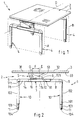
- Figure 2 is a sectional view along the plane A of Figure 1 of the office furniture 1 shows the configuration of the base 4 which is then in the form of "U reversed".
- the tray assembly 2 of the office furniture 1 is fixed to the base 4 by fastening means 5.
- the fastening obtained is then shifted with respect to the vertical axis E of symmetry of the slice of the plate 3 in section along the vertical plane A when the plate 3 is horizontal.
- FIG. 2 illustrates the office furniture when the base has the so-called "inverted U” configuration, the base 4 then being composed of a plate 6 which cooperates by fastening means 5 with the set-plate 2 in order to realize the complete fixation of the latter.
- the main part of the body of the plate 6 extends generally vertically and below the portion 32 of the plate 3.
- the plate 6 is fixed on its lower part 61 to a base 7 which is horizontal regardless of the configuration of the base 4.
- This base 7, generally rectilinear has a tubular structure of rectangular section and comprises two fictitious portions 71 and 72, the portion 72 being defined as the portion which has the axis E as vertical axis of symmetry and the portion 71 defined as the complementary portion of the portion 72 to form the base 7.
- the portion 71 of the base 7 is situated generally vertically and below the portion 31 of the plate 3.
- the end of the portion 72 of the opposite base 7 at the end in contact with the portion 71 of the base 7 and marked 721 while the end of the portion 71 of the base 7 opposite the end in contact with the portion 72 of the base 7 is located 711.
- the base 7 is extended by an extension 8, itself extended by an angular piece 9.
- a second angular piece 9 is fixed in the extension of the portion 71 of the base 7 to the end 711.
- the angular pieces 9 are constructed so that they are each adapted to receive a rising tube 10 arranged vertically and oriented downwards.
- Each riser tube 10 is provided with extension means 101 allowing the length of said riser tube 10 to be adjusted, which allows the height of the tray 3 to be adjusted at the discretion of the user of the office furniture 1 or according to the functions of the user. it is intended for said office furniture 1.
- the adjustment means 101 of a rising tube 10 consist in fact of a unlockable pawl mounted on a first tube 102 forming part of a rising tube 10, said pawl being able to cooperate with a series of lugs arranged on a second tube 103 forming a second portion of a riser tube 10, the second tube 103 slidable in the tube 102. Nevertheless, the skilled person could consider any equivalent and known solution to achieve this type of adjustment.
- each rising tube 10 is designed to so as to be able to receive at its lower end 104 a cylinder 11 which advantageously makes it possible to ensure by a fine adjustment, that the contact is actually continuous and simultaneously at the level of each support on the floor of the office furniture 1, so that the latter is not wobbly.
- the base 4 has the configuration called "I"
- the base 4 is composed of all the elements described in the previous configuration but their relative nesting is different.
- the elements can be fixed relatively to each other.
- the plate 6 on which is fixed the set-plate 2 is supported by the two upright tubes 10 in its lower part 61, arranged vertically and fixed on the plate 6 which extends generally vertically and below the portion 32 of the slice of the plate 3.
- the upright tubes 10 are fixed at their lower end 104 on the base 7 and more precisely on the portion 72 of the base 7.
- the portion 71 of the base 7 is situated generally vertically and below the portion 31 of the edge of the plate 3.
- the base 7 is extended by the extension 8 to the end 721.
- the extension 8 is itself extended by an angular piece 9, the second angular piece 9 is fixed in the extension of the portion 71 of the base 7 at the end 711.
- the angular pieces 9 are constructed so that they are each able to receive a jack 11 which are identical and which then have the same purpose as in the description of the configuration in "U reversed".
- the last possible configuration of base shown in Figure 4 is the so-called "C” configuration where the tray assembly 2 of the office furniture 1 is fixed on the plate 6 which then extends generally vertically and below the portion 31 of the slice of the plate 3.
- the plate 6 is supported by the two tubes 10 in its lower part 61, arranged vertically and fixed on the plate 6.
- the upright tubes 10 are fixed at their lower end 104 on the base 7 and more precisely on the portion 72.
- the portion 71 extends generally vertically and below the portion 32 of the plate 3.
- the base 7 is extended by the extension 8 at the end 711, the extension 8 is itself extended by an angular piece 9, the second angular piece 9 is fixed in the extension of the portion 72 of the base 7 at the end 721.
- the angular pieces 9 each receive a jack 11.
- the set-plate 2 comprises two support consoles 12 whose number is equal to the number of legs 4, fixed on the plate 3 on its lower face 33 and arranged nearby. legs 4 so as to cooperate with the plates 6 of each of the legs 4 in order to achieve the attachment of the plate assembly 2 on the plates 6.
- the attachment of each support bracket 12 on the plate 3 is obtained by any means known to those skilled in the art that ensures that the attachment is easily removable and that these assembly / disassembly operations can be repeated without the quality of the attachment is impaired.
- each support bracket 12 extends generally in a plane parallel to the plane (A, B) of the base 4 with which said support bracket 12 cooperates to achieve the attachment of the tray assembly 2 by means of minus two screws 13 screwed each into a thread 62 made in the plate 6 and each passing through a light 121 made in the support bracket 12 ( Figure 5).
- This type of attachment has the advantage of being particularly simple and fast implementation for both mounting and disassembly and not to be expensive.
- the legs 4 are arranged perpendicularly to the axis D ( Figure 1) and at least one of the lights 121 is an elongated shape of an arcuate shape which allows to adjust the inclination of the 2-tray assembly relative to the horizontal and to achieve the fixing on the plate 6 to the desired inclination by tightening screws 13.
- each plate 6 of each base 4 is inclined relative to the horizontal.
- the two portions 71 and 72 of the base 7 each form an independent part, respectively 14 and 15, nested one inside the other and fixed relative to each other.
- the part 14 is identical to the extender 8, which allows to significantly reduce manufacturing costs by having as much identity as possible in the manufactured parts.
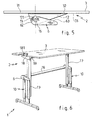
- elevation means 17 are added to the legs 4.
- the set of plateau 2 is then attached to the elevation means 17 which may be of the mechanical type, hydraulic, electrical, a combination of these means or any other type since they have a large amplitude of travel.
- the plate 3 is fixed to the elevating means 17 by means of a plate 18 at each base, identical to a plate 6, said plate being then arranged so that its 181 part equivalent to the lower part 61 of a plate 6 is in contact with the lower face 33 of the plate 3.
- a second stiffening bar 19, in the form of bar or tubular section, identical or not to the bar 16 can connect each plate 18 at the level each base to increase the overall rigidity.
- the range of movement of the means 17 must be between 0 and 600 mm, which allows the user to be standing or sitting according to his wishes and / or obligations.
- a zero elongation corresponds to a standard office height
- an elongation of 400 mm corresponds to a semi-sitting height from the user
- an elongation of 600 mm allows a setting where the operator is standing.
- this effect can be obtained by the actuation of the elevation means 17 conjugated or not to the actuation of the extension means 101.
Landscapes
- Tables And Desks Characterized By Structural Shape (AREA)
- Legs For Furniture In General (AREA)
- Baking, Grill, Roasting (AREA)
- Pyridine Compounds (AREA)
- Table Devices Or Equipment (AREA)
- Furniture Connections (AREA)
- Laminated Bodies (AREA)
- Combinations Of Kitchen Furniture (AREA)
Applications Claiming Priority (1)
| Application Number | Priority Date | Filing Date | Title |
|---|---|---|---|
| FR0407824A FR2873003B1 (fr) | 2004-07-13 | 2004-07-13 | Mobilier de bureau comprenant des pietements a configuration multiple |
Publications (3)
| Publication Number | Publication Date |
|---|---|
| EP1616501A2 true EP1616501A2 (de) | 2006-01-18 |
| EP1616501A3 EP1616501A3 (de) | 2006-07-26 |
| EP1616501B1 EP1616501B1 (de) | 2010-02-17 |
Family
ID=34942468
Family Applications (1)
| Application Number | Title | Priority Date | Filing Date |
|---|---|---|---|
| EP05291463A Expired - Lifetime EP1616501B1 (de) | 2004-07-13 | 2005-07-06 | Büromöbel mit konfigurierbarem Untergestell |
Country Status (4)
| Country | Link |
|---|---|
| EP (1) | EP1616501B1 (de) |
| AT (1) | ATE457665T1 (de) |
| DE (1) | DE602005019349D1 (de) |
| FR (1) | FR2873003B1 (de) |
Cited By (1)
| Publication number | Priority date | Publication date | Assignee | Title |
|---|---|---|---|---|
| DE102018203414B3 (de) | 2018-03-07 | 2019-07-11 | Tobias Benkert | Einstellbarer Tisch |
Family Cites Families (4)
| Publication number | Priority date | Publication date | Assignee | Title |
|---|---|---|---|---|
| DE19920935A1 (de) * | 1999-05-07 | 2000-11-16 | Merkt Konrad Gmbh | Vorrichtung zur Höhenverstellung von Möbelstücken |
| ES2226754T3 (es) * | 1999-12-22 | 2005-04-01 | Ziur I, S.L. | Union perfeccionada para estructuras de muebles, particularmente mesas. |
| US6814946B1 (en) * | 2000-03-03 | 2004-11-09 | Donald B. Peddicord | Salt platform with hub having locking element |
| US20020096609A1 (en) * | 2000-11-13 | 2002-07-25 | Frank Venegas | Modular, collapsible base for furniture, particularly conference tables , and the like |
-
2004
- 2004-07-13 FR FR0407824A patent/FR2873003B1/fr not_active Expired - Fee Related
-
2005
- 2005-07-06 DE DE602005019349T patent/DE602005019349D1/de not_active Expired - Fee Related
- 2005-07-06 EP EP05291463A patent/EP1616501B1/de not_active Expired - Lifetime
- 2005-07-06 AT AT05291463T patent/ATE457665T1/de not_active IP Right Cessation
Cited By (2)
| Publication number | Priority date | Publication date | Assignee | Title |
|---|---|---|---|---|
| DE102018203414B3 (de) | 2018-03-07 | 2019-07-11 | Tobias Benkert | Einstellbarer Tisch |
| EP3536191A1 (de) * | 2018-03-07 | 2019-09-11 | Tobias Benkert | Einstellbarer tisch |
Also Published As
| Publication number | Publication date |
|---|---|
| ATE457665T1 (de) | 2010-03-15 |
| FR2873003A1 (fr) | 2006-01-20 |
| FR2873003B1 (fr) | 2006-09-22 |
| EP1616501A3 (de) | 2006-07-26 |
| EP1616501B1 (de) | 2010-02-17 |
| DE602005019349D1 (de) | 2010-04-01 |
Similar Documents
| Publication | Publication Date | Title |
|---|---|---|
| EP4056070B1 (de) | Tisch mit mittelauszug | |
| EP2422648A1 (de) | Bürovorrichtung mit mehreren räumlichen Konfigurationsmöglichkeiten | |
| EP0517617A1 (de) | Modulare Regale | |
| EP0307336B1 (de) | Element zum Ordnen von Dokumenten oder dergleichen und Zusammensetzung von geneigten Speichereinheiten, bestehend aus mehreren solchen Elementen | |
| FR3115969A1 (fr) | Table à rallonge centrale | |
| EP1616501B1 (de) | Büromöbel mit konfigurierbarem Untergestell | |
| EP1488770A1 (de) | Hebestuhl mit automatisch veränderlicher Neigung der Rückenlehne | |
| FR2586916A3 (fr) | Siege empilable | |
| FR2979526A1 (fr) | Siege ergonomique pourvu d'un profil aluminium vertical incline sur lequel sont fixes ou peuvent coulisser un support d'assise, un support dossier, un repose-pieds et autres accessoires | |
| FR3066897B1 (fr) | Chaise possedant des moyens anti-basculement | |
| FR3131519A1 (fr) | Chaise de bureau pliante | |
| EP0572345B1 (de) | Armlehne für einen Vordersitz eines Fahrzeuges | |
| FR3023461A1 (fr) | Dispositif de suspension pour sommier ou siege du type a lattes | |
| EP1988801B1 (de) | Gondel mit verstellbaren pfosten | |
| FR2931346A1 (fr) | Meuble de bureau convivial | |
| EP0693264A1 (de) | Fusstützenvorrichtung für Arbeitstisch | |
| FR2668909A1 (fr) | Gradin modulaire pourvu de sieges escamotables. | |
| FR3125212A1 (fr) | Dispositif d’appui fessier | |
| FR2854043A1 (fr) | Installation de stockage a elements de rangement coulissants superposes, de type plateaux, tiroirs ou similaires | |
| EP1365671A1 (de) | Einstellbare einstückige schulbank | |
| FR3162601A1 (fr) | Table pour balcon rabattable | |
| FR2984704A1 (fr) | Siege a dossier double face. | |
| EP1304945A1 (de) | Satz von ineinander verschiebaren tischen | |
| FR2717058A1 (fr) | Table modulable. | |
| EP1228790A1 (de) | Zusammenlegbare Werkbank für Skier |
Legal Events
| Date | Code | Title | Description |
|---|---|---|---|
| PUAI | Public reference made under article 153(3) epc to a published international application that has entered the european phase |
Free format text: ORIGINAL CODE: 0009012 |
|
| AK | Designated contracting states |
Kind code of ref document: A2 Designated state(s): AT BE BG CH CY CZ DE DK EE ES FI FR GB GR HU IE IS IT LI LT LU LV MC NL PL PT RO SE SI SK TR |
|
| AX | Request for extension of the european patent |
Extension state: AL BA HR MK YU |
|
| PUAL | Search report despatched |
Free format text: ORIGINAL CODE: 0009013 |
|
| AK | Designated contracting states |
Kind code of ref document: A3 Designated state(s): AT BE BG CH CY CZ DE DK EE ES FI FR GB GR HU IE IS IT LI LT LU LV MC NL PL PT RO SE SI SK TR |
|
| AX | Request for extension of the european patent |
Extension state: AL BA HR MK YU |
|
| 17P | Request for examination filed |
Effective date: 20061120 |
|
| 17Q | First examination report despatched |
Effective date: 20061220 |
|
| AKX | Designation fees paid |
Designated state(s): AT BE BG CH CY CZ DE DK EE ES FI FR GB GR HU IE IS IT LI LT LU LV MC NL PL PT RO SE SI SK TR |
|
| 17Q | First examination report despatched |
Effective date: 20061220 |
|
| GRAP | Despatch of communication of intention to grant a patent |
Free format text: ORIGINAL CODE: EPIDOSNIGR1 |
|
| GRAS | Grant fee paid |
Free format text: ORIGINAL CODE: EPIDOSNIGR3 |
|
| GRAA | (expected) grant |
Free format text: ORIGINAL CODE: 0009210 |
|
| AK | Designated contracting states |
Kind code of ref document: B1 Designated state(s): AT BE BG CH CY CZ DE DK EE ES FI FR GB GR HU IE IS IT LI LT LU LV MC NL PL PT RO SE SI SK TR |
|
| REG | Reference to a national code |
Ref country code: GB Ref legal event code: FG4D Free format text: NOT ENGLISH |
|
| REG | Reference to a national code |
Ref country code: CH Ref legal event code: EP |
|
| REG | Reference to a national code |
Ref country code: IE Ref legal event code: FG4D Free format text: LANGUAGE OF EP DOCUMENT: FRENCH |
|
| REF | Corresponds to: |
Ref document number: 602005019349 Country of ref document: DE Date of ref document: 20100401 Kind code of ref document: P |
|
| REG | Reference to a national code |
Ref country code: NL Ref legal event code: T3 |
|
| LTIE | Lt: invalidation of european patent or patent extension |
Effective date: 20100217 |
|
| PG25 | Lapsed in a contracting state [announced via postgrant information from national office to epo] |
Ref country code: IS Free format text: LAPSE BECAUSE OF FAILURE TO SUBMIT A TRANSLATION OF THE DESCRIPTION OR TO PAY THE FEE WITHIN THE PRESCRIBED TIME-LIMIT Effective date: 20100617 Ref country code: ES Free format text: LAPSE BECAUSE OF FAILURE TO SUBMIT A TRANSLATION OF THE DESCRIPTION OR TO PAY THE FEE WITHIN THE PRESCRIBED TIME-LIMIT Effective date: 20100528 Ref country code: PT Free format text: LAPSE BECAUSE OF FAILURE TO SUBMIT A TRANSLATION OF THE DESCRIPTION OR TO PAY THE FEE WITHIN THE PRESCRIBED TIME-LIMIT Effective date: 20100617 Ref country code: LT Free format text: LAPSE BECAUSE OF FAILURE TO SUBMIT A TRANSLATION OF THE DESCRIPTION OR TO PAY THE FEE WITHIN THE PRESCRIBED TIME-LIMIT Effective date: 20100217 |
|
| PG25 | Lapsed in a contracting state [announced via postgrant information from national office to epo] |
Ref country code: PL Free format text: LAPSE BECAUSE OF FAILURE TO SUBMIT A TRANSLATION OF THE DESCRIPTION OR TO PAY THE FEE WITHIN THE PRESCRIBED TIME-LIMIT Effective date: 20100217 Ref country code: LV Free format text: LAPSE BECAUSE OF FAILURE TO SUBMIT A TRANSLATION OF THE DESCRIPTION OR TO PAY THE FEE WITHIN THE PRESCRIBED TIME-LIMIT Effective date: 20100217 Ref country code: FI Free format text: LAPSE BECAUSE OF FAILURE TO SUBMIT A TRANSLATION OF THE DESCRIPTION OR TO PAY THE FEE WITHIN THE PRESCRIBED TIME-LIMIT Effective date: 20100217 Ref country code: AT Free format text: LAPSE BECAUSE OF FAILURE TO SUBMIT A TRANSLATION OF THE DESCRIPTION OR TO PAY THE FEE WITHIN THE PRESCRIBED TIME-LIMIT Effective date: 20100217 Ref country code: SI Free format text: LAPSE BECAUSE OF FAILURE TO SUBMIT A TRANSLATION OF THE DESCRIPTION OR TO PAY THE FEE WITHIN THE PRESCRIBED TIME-LIMIT Effective date: 20100217 |
|
| REG | Reference to a national code |
Ref country code: IE Ref legal event code: FD4D |
|
| PG25 | Lapsed in a contracting state [announced via postgrant information from national office to epo] |
Ref country code: EE Free format text: LAPSE BECAUSE OF FAILURE TO SUBMIT A TRANSLATION OF THE DESCRIPTION OR TO PAY THE FEE WITHIN THE PRESCRIBED TIME-LIMIT Effective date: 20100217 Ref country code: CY Free format text: LAPSE BECAUSE OF FAILURE TO SUBMIT A TRANSLATION OF THE DESCRIPTION OR TO PAY THE FEE WITHIN THE PRESCRIBED TIME-LIMIT Effective date: 20100217 Ref country code: SE Free format text: LAPSE BECAUSE OF FAILURE TO SUBMIT A TRANSLATION OF THE DESCRIPTION OR TO PAY THE FEE WITHIN THE PRESCRIBED TIME-LIMIT Effective date: 20100217 Ref country code: IE Free format text: LAPSE BECAUSE OF FAILURE TO SUBMIT A TRANSLATION OF THE DESCRIPTION OR TO PAY THE FEE WITHIN THE PRESCRIBED TIME-LIMIT Effective date: 20100217 Ref country code: RO Free format text: LAPSE BECAUSE OF FAILURE TO SUBMIT A TRANSLATION OF THE DESCRIPTION OR TO PAY THE FEE WITHIN THE PRESCRIBED TIME-LIMIT Effective date: 20100217 Ref country code: GR Free format text: LAPSE BECAUSE OF FAILURE TO SUBMIT A TRANSLATION OF THE DESCRIPTION OR TO PAY THE FEE WITHIN THE PRESCRIBED TIME-LIMIT Effective date: 20100518 |
|
| PGFP | Annual fee paid to national office [announced via postgrant information from national office to epo] |
Ref country code: NL Payment date: 20100714 Year of fee payment: 6 |
|
| PG25 | Lapsed in a contracting state [announced via postgrant information from national office to epo] |
Ref country code: CZ Free format text: LAPSE BECAUSE OF FAILURE TO SUBMIT A TRANSLATION OF THE DESCRIPTION OR TO PAY THE FEE WITHIN THE PRESCRIBED TIME-LIMIT Effective date: 20100217 Ref country code: BG Free format text: LAPSE BECAUSE OF FAILURE TO SUBMIT A TRANSLATION OF THE DESCRIPTION OR TO PAY THE FEE WITHIN THE PRESCRIBED TIME-LIMIT Effective date: 20100517 Ref country code: SK Free format text: LAPSE BECAUSE OF FAILURE TO SUBMIT A TRANSLATION OF THE DESCRIPTION OR TO PAY THE FEE WITHIN THE PRESCRIBED TIME-LIMIT Effective date: 20100217 |
|
| PGFP | Annual fee paid to national office [announced via postgrant information from national office to epo] |
Ref country code: FR Payment date: 20100806 Year of fee payment: 6 |
|
| PLBE | No opposition filed within time limit |
Free format text: ORIGINAL CODE: 0009261 |
|
| STAA | Information on the status of an ep patent application or granted ep patent |
Free format text: STATUS: NO OPPOSITION FILED WITHIN TIME LIMIT |
|
| 26N | No opposition filed |
Effective date: 20101118 |
|
| PG25 | Lapsed in a contracting state [announced via postgrant information from national office to epo] |
Ref country code: DK Free format text: LAPSE BECAUSE OF FAILURE TO SUBMIT A TRANSLATION OF THE DESCRIPTION OR TO PAY THE FEE WITHIN THE PRESCRIBED TIME-LIMIT Effective date: 20100217 |
|
| PG25 | Lapsed in a contracting state [announced via postgrant information from national office to epo] |
Ref country code: MC Free format text: LAPSE BECAUSE OF NON-PAYMENT OF DUE FEES Effective date: 20100731 |
|
| PGFP | Annual fee paid to national office [announced via postgrant information from national office to epo] |
Ref country code: BE Payment date: 20100715 Year of fee payment: 6 |
|
| REG | Reference to a national code |
Ref country code: CH Ref legal event code: PL |
|
| GBPC | Gb: european patent ceased through non-payment of renewal fee |
Effective date: 20100706 |
|
| PG25 | Lapsed in a contracting state [announced via postgrant information from national office to epo] |
Ref country code: IT Free format text: LAPSE BECAUSE OF FAILURE TO SUBMIT A TRANSLATION OF THE DESCRIPTION OR TO PAY THE FEE WITHIN THE PRESCRIBED TIME-LIMIT Effective date: 20100217 |
|
| PG25 | Lapsed in a contracting state [announced via postgrant information from national office to epo] |
Ref country code: DE Free format text: LAPSE BECAUSE OF NON-PAYMENT OF DUE FEES Effective date: 20110201 Ref country code: CH Free format text: LAPSE BECAUSE OF NON-PAYMENT OF DUE FEES Effective date: 20100731 Ref country code: LI Free format text: LAPSE BECAUSE OF NON-PAYMENT OF DUE FEES Effective date: 20100731 |
|
| REG | Reference to a national code |
Ref country code: DE Ref legal event code: R119 Ref document number: 602005019349 Country of ref document: DE Effective date: 20110201 |
|
| PG25 | Lapsed in a contracting state [announced via postgrant information from national office to epo] |
Ref country code: GB Free format text: LAPSE BECAUSE OF NON-PAYMENT OF DUE FEES Effective date: 20100706 |
|
| BERE | Be: lapsed |
Owner name: INTER COMPANY COMPUTER ENGINEERING DESIGN SERVICE Effective date: 20110731 |
|
| REG | Reference to a national code |
Ref country code: NL Ref legal event code: V1 Effective date: 20120201 |
|
| REG | Reference to a national code |
Ref country code: FR Ref legal event code: ST Effective date: 20120330 |
|
| PG25 | Lapsed in a contracting state [announced via postgrant information from national office to epo] |
Ref country code: FR Free format text: LAPSE BECAUSE OF NON-PAYMENT OF DUE FEES Effective date: 20110801 Ref country code: BE Free format text: LAPSE BECAUSE OF NON-PAYMENT OF DUE FEES Effective date: 20110731 |
|
| PG25 | Lapsed in a contracting state [announced via postgrant information from national office to epo] |
Ref country code: NL Free format text: LAPSE BECAUSE OF NON-PAYMENT OF DUE FEES Effective date: 20120201 |
|
| PG25 | Lapsed in a contracting state [announced via postgrant information from national office to epo] |
Ref country code: LU Free format text: LAPSE BECAUSE OF NON-PAYMENT OF DUE FEES Effective date: 20100706 Ref country code: HU Free format text: LAPSE BECAUSE OF FAILURE TO SUBMIT A TRANSLATION OF THE DESCRIPTION OR TO PAY THE FEE WITHIN THE PRESCRIBED TIME-LIMIT Effective date: 20100818 |
|
| PG25 | Lapsed in a contracting state [announced via postgrant information from national office to epo] |
Ref country code: TR Free format text: LAPSE BECAUSE OF FAILURE TO SUBMIT A TRANSLATION OF THE DESCRIPTION OR TO PAY THE FEE WITHIN THE PRESCRIBED TIME-LIMIT Effective date: 20100217 |