EP1616602B1 - Zusatzelement für die Oberseite von Schneegleitbretter - Google Patents
Zusatzelement für die Oberseite von Schneegleitbretter Download PDFInfo
- Publication number
- EP1616602B1 EP1616602B1 EP05291457A EP05291457A EP1616602B1 EP 1616602 B1 EP1616602 B1 EP 1616602B1 EP 05291457 A EP05291457 A EP 05291457A EP 05291457 A EP05291457 A EP 05291457A EP 1616602 B1 EP1616602 B1 EP 1616602B1
- Authority
- EP
- European Patent Office
- Prior art keywords
- snow
- board
- sliding
- complementary element
- towards
- Prior art date
- Legal status (The legal status is an assumption and is not a legal conclusion. Google has not performed a legal analysis and makes no representation as to the accuracy of the status listed.)
- Expired - Lifetime
Links
Images





Classifications
-
- A—HUMAN NECESSITIES
- A63—SPORTS; GAMES; AMUSEMENTS
- A63C—SKATES; SKIS; ROLLER SKATES; DESIGN OR LAYOUT OF COURTS, RINKS OR THE LIKE
- A63C5/00—Skis or snowboards
- A63C5/04—Structure of the surface thereof
-
- A—HUMAN NECESSITIES
- A63—SPORTS; GAMES; AMUSEMENTS
- A63C—SKATES; SKIS; ROLLER SKATES; DESIGN OR LAYOUT OF COURTS, RINKS OR THE LIKE
- A63C5/00—Skis or snowboards
- A63C5/003—Structure, covering or decoration of the upper ski surface
-
- A—HUMAN NECESSITIES
- A63—SPORTS; GAMES; AMUSEMENTS
- A63C—SKATES; SKIS; ROLLER SKATES; DESIGN OR LAYOUT OF COURTS, RINKS OR THE LIKE
- A63C5/00—Skis or snowboards
- A63C5/12—Making thereof; Selection of particular materials
- A63C5/128—A part for the binding being integrated within the board structure, e.g. plate, rail, insert
Definitions
- the present invention relates to a snow board on snow such as a ski, a monoski, a surf, or other. It relates more particularly to an improvement relating to a gliding board comprising a base, on which is fixed at least one complementary element.
- gliding boards and in particular skis, which are constituted by an elongated beam whose front end is raised to form the spatula, while the lower surface comprises a sliding sole bordered by metal edges.
- the present invention provides multipurpose skis consisting of a base and at least one complementary element whose cooperation of shapes, dimensions and structure, gives the whole of ski its necessary characteristics, as much of comfort as of driving of ski.
- the gliding board on snow such as a ski, a monoski or a surf, of vertical plane of general symmetry
- the gliding board on snow is of the type comprising a main part, said body or base, comprising at least in the zone of the shoe two recessed lateral housing extending longitudinally to form a longitudinal rib, each of the longitudinal housing opening at least upwards, in which said body is fixed at least in the zone of the pad a complementary element consisting of two parts longitudinal sides extending longitudinally substantially parallel, the two longitudinal side portions being fixed in said hollow recesses, characterized in that the two longitudinal side portions are interconnected by at least one transverse connecting portion, which is integral with the longitudinal side parts and in that the longitudinal lateral parts extend over a length greater than 30% of the length of the base.
- the two longitudinal lateral parts are interconnected by two transverse connection parts.
- each of the recessed lateral recesses constitutes two grooves which open upwards according to another complementary characteristic each of the recessed lateral recesses constitute two lateral recesses which open laterally towards the outside and upwards, while they do not open down to form a lower side edge.
- the thickness of the lower side edge of the base and the height of the longitudinal side portions of the complementary element progressively decrease from the ski center, towards the front and / or towards the rear.
- the thickness of the lower side edge of the base is constant, while the height of the longitudinal side portions of the complementary element, is variable.
- the height of the longitudinal side portions of the complementary element decreases from the center of the ski forward and / or backward.
- the thickness of the lower side edge of the base is variable, while the height of the longitudinal side portions of the complementary element, is constant.
- the thickness of the base lateral edge may be constant to decrease from the center of the ski forward and / or backward.
- the height of each one or / and the other of the longitudinal side portions of the complementary element is equal to or greater than the height of the corresponding clearances.
- the base has its own distribution of thickness, coastline, width and stiffness.
- the width of the side clearances is variable longitudinally, to be greater in the center of the ski, and to decrease forwards and / or backwards.
- the longitudinal side part or parts of the complementary element are constituted by elongated profiles whose transverse section evolves in its dimensions and / or in its forms.
- the width of the longitudinal lateral parts of the complementary element may be variable longitudinally, to be greater in the center of the ski, and to decrease towards the front and / or towards the rear.
- the length of the longitudinal side portions of the complementary element is equal to or greater than 30% of the length of the base.
- each of the longitudinal lateral parts of the complementary element is slightly greater than the height of the corresponding clearance.
- the complementary element is a hollow profile, made of composite material, and is made by thermoforming or hot forming a composite sheet material.
- a determined base corresponds to a set of several different complementary elements.
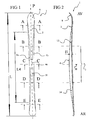
- the ski with the general reference (1) is a set of elongate shapes having a median vertical (P) plane of general symmetry whose front is raised to form the spatula (8).
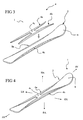
- the ski (1) is constituted by a main part that we will call body or base (2) on which at least one complementary element (4) is fixed at least in the region of the shoe (3)
- the base (2) is the element in contact with the snow and has the shape of an elongate beam having on its lower surface a sliding sole (6) laterally bordered by lateral edges (7a, 7b) of metal.
- the base (2) is an elongate beam whose front end is raised to form the spatula (8) of the ski.
- This base (2) has its own distribution of thickness, coastline, width and stiffness and can be of all types and constitutions.
- the elongate beam constituting the base (2) can be of all types of designs such as those known to date as, for example, sandwich type, box type, or shell type, or even the type combining shell and side fields, taken alone or in combination, or mixed and consisting of a set of elements and components known in themselves.
- the figure 10 ' is a schematic cross-sectional view of a ski associating a shell, and lateral fields (20a, 20b).
- the complementary element (4) is intended to participate in the flexural holding of the ski, and therefore acts as a stiffener.
- the complementary element (4) has the general shape of an "H", and comprises two longitudinal longitudinal portions (4a, 4b) extending longitudinally, and which are connected by a transverse portion of link (4c) extending transversely, substantially in the middle zone of the complementary element.
- the complementary element (4) could comprise two transverse connecting parts (4c, 4'c) connecting the two longitudinal side portions (4a, 4b) as shown in FIGS. Figures 14 and 14a .
- the complementary element (4) comprises in such a variant, a front link portion (4c) and a rear link portion (4'c).
- the two longitudinal lateral parts (4a, 4b) are advantageously constituted by elongate profiles, the section of which in a transverse section is advantageously progressive, in its dimensions and / or in its shapes.
- each of the longitudinal side portions (4a, 4b) has its own configuration and structure, its own distribution of thickness, width and stiffness and can be of all types of constructions.
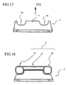
- the complementary element (4) with its two longitudinal lateral parts (4a, 4b) can be formed by a monobloc element made of one and the same material. But it can be of a completely different design as, for example, formed by a profile having substantially the shape of a tube comprising an outer wall made, for example, composite material, whose central portion would be empty or filled with a filler, such as a synthetic foam, as shown in FIG. figure 18 .
- the complementary element is for example obtained by thermoforming or hot forming.
- each of the longitudinal lateral parts (4a, 4b) is a profile whose section advantageously decreases progressively from the central zone (30) towards the front (AV) and towards the rear ( AR), in width and thickness.
- the base (2) comprises lateral recesses (8a, 8b) in each of which is fixed one of the longitudinal side parts (4a, 4b).
- the base (2) comprises a left lateral clearance (8a) in which is fixed the left longitudinal side portion (4a), and a right lateral clearance (8b) in which is fixed the left longitudinal side portion (4b).
- each of the side clearances is partially complementary shape to receive the corresponding longitudinal side portion (4a, 4b).
- each of the side clearances (8a, 8b) opens laterally outward (EX) and upward (HA), while it does not open downwards (BA), to form two lateral housings (8a, 8b), intended to receive the longitudinal lateral parts (4a, 4b) of the complementary element (4).
- width (L1) of the clearances is advantageously longitudinally variable, to be wider in the center (30) of the ski (1), and advantageously decrease progressively, forward (AV) or rearward (AR), and advantageously forward (AV) and backward (AR).
- the height (H1) of the clearances (8a, 8b) is advantageously longitudinally variable, to be greater in the center of the ski, and advantageously decrease progressively, forward (AV) or rearward (AR), and advantageously forward (AV) and backward (AR).
- the height (H2) of the profile of the two longitudinal lateral parts (4a, 4b) is greater than the height (H1) of the corresponding clearance (8a, 8b), and this, over all or part of the length of the longitudinal side portion of the complementary element. But, according to the preferred mode, it is the height (H2) of the profile of the two longitudinal side portions (4a, 4b) which is greater than the height (H1) of the corresponding recess (8a, 8b),
- the general plane (P3) of the upper surface (40) of the longitudinal side portions (4a, 4b) is located above the plane (P1) of the upper surface (110) of the longitudinal rib (11).
- the height (H2) of the profile of each of the longitudinal lateral parts (4a, 4b) of the complementary element (4) could be equal to the height (H1) of the clearance or corresponding housing (8a, 8b ), and this, along the entire length of the complementary element.
- the general plane (P3) of the upper surface (40) of the longitudinal side portions (4a, 4b) would be located in the same general plane (P1) of the upper surface (110) of the longitudinal rib (11).
- the height (H2) of the profile of at least one of the longitudinal lateral parts (4a, 4b) of the complementary element (4) may be equal to or greater than the height (H1) of the openings or corresponding housing (8a, 8b).
- the width (L2) of the longitudinal lateral portions (4a, 4b) of the complementary element (4) is advantageously variable longitudinally, to be wider at the center of the ski, and advantageously to decrease progressively from the center (30) of the ski (1), forward (AV) or rearward (AR), while their height (H2) is also advantageously progressively variable forward (AV) and rearward (AR) longitudinally for be greater in the center (30) of the ski (1), and decrease in the forward (AV) or rearward (AR),
- the height (H), namely, the thickness of the ski (1), that is to say the height of the base (2) plus the height of the lateral parts longitudinal (4a, 4b) is equal to the distance between the upper surface (40) of the longitudinal side portions (4a, 4b) and the lower sliding surface (6).
- the height (H) corresponding to the thickness of the ski (1) at the longitudinal side portions (4a, 4b) is equal to the height (H2) of said lateral portions plus the thickness (H3) of the lateral edge (20) of the base (2).
- height (H) is variable to advantageously decrease progressively forward (AV) or rearward (AR), and advantageously forward (AV) and rearward (AR).
- the overall length (L4) of the complementary element (4) and in particular of its longitudinal lateral parts (4a, 4b) may extend over all or part of the length of the base . It may be, for example, equal to or greater than 30% of the length (L) of the base (2), such as, for example, between 30% and 90%.
- the length (L4) of the complementary element may have, for example, a length of between 50 and 150 centimeters, for a ski having a length of 170 centimeters.
- the two longitudinal side portions (4a, 4b) of the complementary element (4) advantageously have the same length, but may have different lengths.
- the length of one of the longitudinal portions (4a or 4b) may be longer than the other longitudinal portion (4b or 4a).
- each of the elements may be as illustrated, but may be of square round, rectangular or other section. Note also that the shape of the section can be scalable and vary longitudinally.
- a base (2) may correspond to a set of several complementary elements (4, 4 ', 4 ").
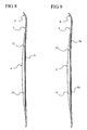
- a given base (2) may correspond several complementary elements of different lengths (L4, L'4, L "4), and, for example, three complementary elements of different lengths, as illustrated in FIG. figure 7 .
- at a determined base (2) can correspond several complementary elements of different thicknesses.
- at a specific base (2) can also correspond, several complementary elements of different mechanical characteristics, intended to confer on the ski (1) constituted by the base (2) and its complementary element (4) characteristics of different behaviors. The different characteristics can be obtained by different thicknesses of the complementary elements, or by a different structure, or even different materials, or even a different geometry.
- connection (9) can be performed over the entire surface of the complementary element (4) common with its housing, as illustrated in FIG. figure 8 , or this connection (9a, 9b) can be made only on a part of the surface as, for example, in the areas of front part (13) and rear (14), as shown in the figure 9 .
- connection of the complementary element (4) to the base (2) is carried out mechanically, for example by projecting recess (15) in corresponding holes (16), such as that is represented by the figure 10 .
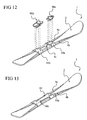
- the figures 11 and 12 illustrate how the ski bindings (90a, 90b) for retaining the skier's boot can be fixed.
- it is, for example, provided two brackets, front (10a) back (10b), on which are fixed the fasteners (90a, 90b), said stirrups being attached to the complementary side elements.
- the stirrup can be attached to the lateral complementary elements (3a, 3b) by any known means, gluing, screws, etc.
- transverse connecting part (4c) could also serve as a platform on which the fasteners (90a, 90b) would be mounted, and would then be of sufficient length.
- the fasteners (90a, 90b) could not be fixed to an intermediate stirrup, such as the stirrups previously described, but could be fixed on the longitudinal lateral parts (4a, 4b) of the complementary element (4) or, of course, on the base (2).
- the figure 13 is a view similar to the figure 12 , showing an alternative embodiment in which the two stirrups (10a, 10b) are connected to each other to form a single stirrup (10).
- the base (2) comprises a longitudinal rib (11) bordered by the two lateral recesses (8a, 8b), the width (L5) of which is smaller than the width (L6) of the lower part (12) of said base (2).
- Each of the lateral clearances is therefore limited towards the plane of symmetry (P) by the longitudinal rib (11) and downwards by the lower part (12) of the base which comprises the metal edges (7a 7b) and the sole of slip (6).
- the ski (1) may be such that the left longitudinal lateral part (4a) is different from the right longitudinal lateral part (4b) by its length, as already mentioned above, but by its section, its transverse dimensions, its constructive characteristics, even its technical characteristics.
- the upper surface (40) of one of the longitudinal lateral parts is not necessarily at the same level as the upper surface (40) of the other of the lateral parts.
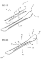
- the two recessed lateral recesses (8a, 8b) extending longitudinally open upwards and laterally to form two lateral recesses, but it could be otherwise without departing from the invention. Indeed, these two lateral housings intended to receive the longitudinal side portions of the complementary element, could only lead upwards to form two lateral grooves as illustrated in FIGS. Figures 15.16 , 17 .
- the complementary element forming the stiffener for the base (2) can, as we said earlier, be made from composite material sheet.
- cross-linking portion (4c) is according to the exemplary illustrations fixed on the surface (110) of the central rib (11), but it could be otherwise, as by example housed in a transverse groove formed in the longitudinal rib (11) of the base.
Landscapes
- Footwear And Its Accessory, Manufacturing Method And Apparatuses (AREA)
- Materials Applied To Surfaces To Minimize Adherence Of Mist Or Water (AREA)
- Road Paving Structures (AREA)
- Fittings On The Vehicle Exterior For Carrying Loads, And Devices For Holding Or Mounting Articles (AREA)
- Acyclic And Carbocyclic Compounds In Medicinal Compositions (AREA)
- Control Of Motors That Do Not Use Commutators (AREA)
Claims (23)
- Schneegleitbrett (1), beispielsweise Ski, Monoski oder Snowboard, mit einer allgemeinen vertikalen Symmetrieebene (P), umfassend einen Körper oder Sockel (2) genannten Hauptteil, mit, mindestens im Bereich des Tragsegments (3), zwei seitlichen Aufnahmevertiefungen (8a, 8b), die sich in Längsrichtung erstrecken und dabei eine Längsrippe (11) bilden, wobei jede der längslaufenden Aufnahmen (8a, 8b) mindestens nach oben (HA) mündet, in dem an dem Körper (2) mindestens im Bereich des Tragsegments (3) ein Gegenstück (4), bestehend aus zwei sich im Wesentlichen parallel zueinander in Längsrichtung erstreckenden, längslaufenden seitlichen Teilen (4a, 4b), befestigt ist, wobei die beiden längslaufenden seitlichen Teile (4a, 4b) in den Aufnahmevertiefungen (8a, 8b) befestigt sind, während die beiden längslaufenden seitlichen Teile (4a, 4b) durch mindestens ein der Verbindung dienendes Querteil (4c) miteinander verbunden sind, dadurch gekennzeichnet, dass das durch die beiden längslaufenden seitlichen Teile (4a, 4b) und durch das der Verbindung dienende Querteil (4c) gebildete Gegenstück (4) ein aus demselben Material bestehendes einstückiges Teil ist und dass die längslaufenden seitlichen Teile (4a, 4b) sich über eine Länge erstrecken, die mehr als 30 % der Länge (L) des Sockels (2) beträgt.
- Schneegleitbrett (1) nach Anspruch 1, dadurch gekennzeichnet, dass die beiden längslaufenden seitlichen Teile (4a, 4b) durch zwei der Verbindung dienende Querteile (4c, 4d) miteinander verbunden sind.
- Schneegleitbrett (1) nach Anspruch 1 oder 2, dadurch gekennzeichnet, dass jede der seitlichen Aufnahmevertiefungen (8a, 8b) zwei nach oben (HA) mündende Nuten ausbilden.
- Schneegleitbrett (1) nach Anspruch 1 oder 2, dadurch gekennzeichnet, dass jede der seitlichen Aufnahmevertiefungen (8a, 8b) zwei seitliche Aussparungen ausbilden, die zur Bildung eines unteren seitlichen Randes (20) seitlich nach außen (EX) und nach oben (HA) aber nicht nach unten (BA) münden.
- Schneegleitbrett (1) nach einem der Ansprüche 1 bis 4, dadurch gekennzeichnet, dass die Stärke (H3) des unteren seitlichen Randes (20) des Sockels (2) sowie die Höhe (H2) der längslaufenden seitlichen Teile (4a, 4b) des Gegenstücks (4) veränderlich sind.
- Schneegleitbrett (1) nach Anspruch 5, dadurch gekennzeichnet, dass die Stärke (H3) des unteren seitlichen Randes (20) des Sockels (2) sowie die Höhe (H2) der längslaufenden seitlichen Teile (4a, 4b) des Gegenstücks (4) von der Mitte (30) des Skis (1) nach vorn und/oder nach hinten abnehmen.
- Schneegleitbrett (1) nach Anspruch 5, dadurch gekennzeichnet, dass die Stärke (H3) des unteren seitlichen Randes (20) des Sockels (2) sowie die Höhe (H2) der längslaufenden seitlichen Teile (4a, 4b) des Gegenstücks (4) von der Mitte (30) des Skis (1) nach vorn und/oder nach hinten kontinuierlich abnehmen.
- Schneegleitbrett (1) nach einem der Ansprüche 1 bis 4, dadurch gekennzeichnet, dass die Stärke (H3) des unteren seitlichen Randes (20) des Sockels (2) konstant bleibt, während die Höhe (H2) der längslaufenden seitlichen Teile (4a, 4b) des Gegenstücks (4) veränderlich ist.
- Schneegleitbrett (1) nach Anspruch 8, dadurch gekennzeichnet, dass die Höhe (H2) der längslaufenden seitlichen Teile (4a, 4b) des Gegenstücks (4) von der Mitte des Skis nach vorn und/oder nach hinten abnimmt.
- Schneegleitbrett (1) nach Anspruch 9, dadurch gekennzeichnet, dass die Höhe (H2) der längslaufenden seitlichen Teile (4a, 4b) des Gegenstücks (4) von der Mitte des Skis nach vorn und nach hinten kontinuierlich abnimmt.
- Schneegleitbrett (1) nach einem der Ansprüche 1 bis 4, dadurch gekennzeichnet, dass die Stärke (H3) des unteren seitlichen Randes (20) des Sockels (2) veränderlich ist, während die Höhe (H2) der längslaufenden seitlichen Teile (4a, 4b) des Gegenstücks (4) konstant bleibt.
- Schneegleitbrett (1) nach Anspruch 11, dadurch gekennzeichnet, dass die Stärke (H3) des seitlichen Randes (20) des Sockels (2) veränderlich ist, wobei sie von der Mitte des Skis nach vorn und/oder nach hinten abnimmt.
- Schneegleitbrett (1) nach Anspruch 12, dadurch gekennzeichnet, dass die Stärke (H3) des seitlichen Randes (20) des Sockels (2) veränderlich ist, wobei sie von der Mitte des Skis nach vorn und/oder nach hinten kontinuierlich abnimmt.
- Schneegleitbrett (1) nach einem der vorstehenden Ansprüche, dadurch gekennzeichnet, dass die Höhe (H2) eines jeden oder beider der längslaufenden seitlichen Teile (4a, 4b) des Gegenstücks (4) größer oder gleich der Höhe (H1) der entsprechenden Aussparungen (8a, 8b) ist.
- Schneegleitbrett (1) nach einem der vorstehenden Ansprüche, dadurch gekennzeichnet, dass der Sockel (2) seine eigene Verteilung hinsichtlich der Stärke, der Maßlinie, der Breite und der Steifheit hat.
- Schneegleitbrett (1) nach Anspruch 15, dadurch gekennzeichnet, dass die Breite (L1) der seitlichen Aussparungen (8a, 8b) in Längsrichtung veränderlich ist, wobei sie in der Mitte des Skis größer ist und nach vorn (AV) und/oder nach hinten (AR) abnimmt.
- Schneegleitbrett (1) nach einem der vorstehenden Ansprüche, dadurch gekennzeichnet, dass eines oder beide der längslaufenden seitlichen Teile (4a, 4b) des Gegenstücks (4) durch längliche Profile gebildet sind.
- Schneegleitbrett (1) nach Anspruch 17, dadurch gekennzeichnet, dass eines oder beide der längslaufenden seitlichen Teile (4a, 4b) des Gegenstücks (4) einen in seinen Abmessungen und/oder seiner Form sich entwickelnden Querschnitt aufweisen.
- Schneegleitbrett (1) nach Anspruch 17 oder 18, dadurch gekennzeichnet, dass die Breite (L2) der längslaufenden seitlichen Teile (4a, 4b) des Gegenstücks (4) in Längsrichtung veränderlich ist, wobei sie in der Mitte des Skis größer ist und nach vorn (AV) und/oder nach hinten (AR) abnimmt.
- Schneegleitbrett (1) nach einem der Ansprüche 14 bis 20, dadurch gekennzeichnet, dass die Höhe (H2) des Profils jedes der längslaufenden seitlichen Teile (4a, 4b) des Gegenstücks (4) leicht größer ist als die Höhe (H1) der entsprechenden Aussparung (8a, 8b).
- Schneegleitbrett (1) nach einem der vorstehenden Ansprüche, dadurch gekennzeichnet, dass das Gegenstück ein aus einem Verbundwerkstoff hergestelltes Hohlprofil ist.
- Schneegleitbrett (1) nach einem der vorstehenden Ansprüche, dadurch gekennzeichnet, dass einem bestimmten Sockel (2) ein Satz mehrerer unterschiedlicher Gegenstücke (4, 4', 4") entspricht.
- Verfahren zur Herstellung des Gegenstücks (4) nach einem der vorstehenden Ansprüche, dadurch gekennzeichnet, dass es durch Thermoformung oder durch Warmumformung einer Folie aus Verbundwerkstoff hergestellt wird.
Applications Claiming Priority (1)
| Application Number | Priority Date | Filing Date | Title |
|---|---|---|---|
| FR0407955A FR2873043B1 (fr) | 2004-07-15 | 2004-07-15 | Perfectionnement pour planche de glisse sur neige |
Publications (2)
| Publication Number | Publication Date |
|---|---|
| EP1616602A1 EP1616602A1 (de) | 2006-01-18 |
| EP1616602B1 true EP1616602B1 (de) | 2008-04-09 |
Family
ID=34949585
Family Applications (1)
| Application Number | Title | Priority Date | Filing Date |
|---|---|---|---|
| EP05291457A Expired - Lifetime EP1616602B1 (de) | 2004-07-15 | 2005-07-05 | Zusatzelement für die Oberseite von Schneegleitbretter |
Country Status (5)
| Country | Link |
|---|---|
| US (1) | US7419179B2 (de) |
| EP (1) | EP1616602B1 (de) |
| AT (1) | ATE391536T1 (de) |
| DE (1) | DE602005005901T2 (de) |
| FR (1) | FR2873043B1 (de) |
Families Citing this family (11)
| Publication number | Priority date | Publication date | Assignee | Title |
|---|---|---|---|---|
| FR2895914B1 (fr) * | 2006-01-09 | 2008-07-04 | Skis Rossignol Sas Soc Par Act | Perfectionnement pour planche de glisse sur neige |
| FR2897275A1 (fr) * | 2006-01-26 | 2007-08-17 | Skis Rossignol Sas Soc Par Act | Planche de glisse sur neige comprenant deux elements complementaires associes a un organe de liaison |
| US7690674B2 (en) * | 2006-08-10 | 2010-04-06 | Armada Skis, Inc. | Snow riding implement |
| AT504800B1 (de) * | 2007-02-02 | 2010-05-15 | Atomic Austria Gmbh | Schi oder snowboard mit einem plattenartigen kraftübertragungselement |
| FR2926735B1 (fr) * | 2008-01-25 | 2010-03-26 | Salomon Sa | Ski alpin avec moyens de reglage |
| AT507579B1 (de) | 2008-12-11 | 2011-01-15 | Atomic Austria Gmbh | Schi oder snowboard mit einem plattenartigen kraftübertragungselement |
| US9305120B2 (en) | 2011-04-29 | 2016-04-05 | Bryan Marc Failing | Sports board configuration |
| FR3003179B1 (fr) * | 2013-03-18 | 2016-08-26 | Salomon Sas | Plaque d'interface pour ski |
| US9950242B2 (en) * | 2015-06-19 | 2018-04-24 | Anton F. Wilson | Automatically adaptive ski |
| FR3084596B1 (fr) * | 2018-08-01 | 2020-07-10 | Skis Rossignol | Ski alpin |
| US10265605B1 (en) | 2018-09-05 | 2019-04-23 | Kyle Mozlin | Apparatus for gliding over snow |
Family Cites Families (15)
| Publication number | Priority date | Publication date | Assignee | Title |
|---|---|---|---|---|
| FR2674443B1 (fr) * | 1991-03-27 | 1993-05-21 | Salomon Sa | Ski a face superieure nervuree. |
| DE69101280T2 (de) * | 1990-07-09 | 1994-06-09 | Salomon Sa | Ski mit gerippter Oberfläche. |
| EP0490044A1 (de) * | 1990-12-14 | 1992-06-17 | Salomon S.A. | Wintersportski bestehend aus einer Versteifung und einer Basis |
| DE69101217T2 (de) * | 1990-12-14 | 1994-06-09 | Salomon Sa | Ski mit laufflächenteil, ober Körper und Support für Bindungen. |
| FR2689411B1 (fr) * | 1992-04-01 | 1994-06-03 | Salomon Sa | Ski comprenant une embase et un raidisseur en deux parties relie a l'embase. |
| FR2693379B1 (fr) * | 1992-07-09 | 1994-09-23 | Salomon Sa | Ski nervure muni d'un support. |
| FR2703916B1 (fr) * | 1993-04-16 | 1995-05-19 | Rossignol Sa | Ski comportant des chants et une coque supérieure. |
| FR2734489B1 (fr) * | 1995-05-22 | 1997-07-04 | Rossignol Sa | Planche de glisse sur neige "a demi-coque", pourvue de chants de support de la coque |
| FR2734492B1 (fr) * | 1995-05-22 | 1997-06-27 | Rossignol Sa | Planche de glisse sur neige comportant un dispositif pour le montage d'une fixation d'une chaussure |
| USD404079S (en) * | 1997-02-06 | 1999-01-12 | Salomon S.A. | Ski |
| FR2773998B1 (fr) * | 1998-01-29 | 2000-02-25 | Rossignol Sa | Planche de glisse comportant une plateforme rigide de surelevation |
| FR2812211B1 (fr) * | 2000-07-28 | 2003-02-07 | Salomon Sa | Planche de glisse |
| AT411152B9 (de) * | 2000-12-18 | 2004-01-26 | Fischer Gmbh | Verbindungseinrichtung zum anschluss einer skibindung an den ski |
| FR2820984B1 (fr) * | 2001-02-20 | 2003-06-06 | Rossignol Sa | Plateforme de rehaussement de la fixation d'une planche de glisse, et planche de glisse equipee d'une telle plateforme |
| FR2834906B1 (fr) * | 2002-01-24 | 2004-04-02 | Rossignol Sa | Perfectionnement pour planche de glisse sur neige |
-
2004
- 2004-07-15 FR FR0407955A patent/FR2873043B1/fr not_active Expired - Fee Related
-
2005
- 2005-07-05 EP EP05291457A patent/EP1616602B1/de not_active Expired - Lifetime
- 2005-07-05 AT AT05291457T patent/ATE391536T1/de not_active IP Right Cessation
- 2005-07-05 DE DE602005005901T patent/DE602005005901T2/de not_active Expired - Fee Related
- 2005-07-15 US US11/182,924 patent/US7419179B2/en not_active Expired - Fee Related
Also Published As
| Publication number | Publication date |
|---|---|
| US20060012150A1 (en) | 2006-01-19 |
| EP1616602A1 (de) | 2006-01-18 |
| US7419179B2 (en) | 2008-09-02 |
| ATE391536T1 (de) | 2008-04-15 |
| DE602005005901T2 (de) | 2009-05-28 |
| DE602005005901D1 (de) | 2008-05-21 |
| FR2873043A1 (fr) | 2006-01-20 |
| FR2873043B1 (fr) | 2008-10-03 |
Similar Documents
| Publication | Publication Date | Title |
|---|---|---|
| EP0577947B1 (de) | Ski mit einer Rippe und einer Stützvorrichtung | |
| EP0543743B2 (de) | Ski mit nicht rechteckigem Schnitt | |
| EP0787440B1 (de) | Sohle für Sportschuh | |
| EP1331026B1 (de) | Verbesserung von Gleittbrettern | |
| EP0465794B1 (de) | Ski mit gerippter Oberfläche | |
| EP1616602B1 (de) | Zusatzelement für die Oberseite von Schneegleitbretter | |
| EP0543744B1 (de) | Ski mit einem nicht-rechteckigen Durchschnitt | |
| EP1314459B1 (de) | Verbesserung für ein Snowboard | |
| EP1484090A1 (de) | Verbesserung für Gleittbretter | |
| FR2746265A1 (fr) | Chaussure de surf | |
| EP1813320B1 (de) | Schneegleitbrett, das zwei Zusatzelemente umfasst, die mit einem Verbindungsorgan verbunden sind | |
| EP1424108B1 (de) | Schneegleitbrett mit seitliche Abstützungplatte | |
| EP2305055A1 (de) | Skischuhserie mit mindestens ein Skischuh der eine Doppelung beinhaltet | |
| EP1813319A1 (de) | Verbesserung für Schneegleitbrett | |
| EP2353672B1 (de) | Gleitbrett für Schnee mit Seitenwange variabler Breite | |
| FR2986436A1 (fr) | Planche de glisse sur neige | |
| EP3632513B1 (de) | Gleitbrett mit eingespritzem kern, das mit längsverstärkungselementen ausgestattet ist | |
| EP1808202B1 (de) | Verbesserung für ein Snowboard | |
| FR2731596A1 (fr) | Ensemble chaussure-fixation-ski pour la pratique du ski de fond | |
| FR2819690A1 (fr) | Chaussure pour raquette a neige avec son insert | |
| FR2674443A1 (fr) | Ski a face superieure nervuree. | |
| FR3016528A1 (fr) | Planche de glisse sur neige, et ensemble comportant une telle planche de glisse et une bande de materiau anti-recul | |
| FR2675390A1 (fr) | Ski pour sport d'hiver comprenant une embase, un raidisseur et un support pour fixations. | |
| FR2834905A1 (fr) | Perfectionnement pour planche de glisse sur neige | |
| FR2778340A1 (fr) | Fixation d'une toile de raquette a neige et son procede de fabrication |
Legal Events
| Date | Code | Title | Description |
|---|---|---|---|
| PUAI | Public reference made under article 153(3) epc to a published international application that has entered the european phase |
Free format text: ORIGINAL CODE: 0009012 |
|
| AK | Designated contracting states |
Kind code of ref document: A1 Designated state(s): AT BE BG CH CY CZ DE DK EE ES FI FR GB GR HU IE IS IT LI LT LU LV MC NL PL PT RO SE SI SK TR |
|
| AX | Request for extension of the european patent |
Extension state: AL BA HR MK YU |
|
| AKX | Designation fees paid | ||
| REG | Reference to a national code |
Ref country code: DE Ref legal event code: 8566 |
|
| 17P | Request for examination filed |
Effective date: 20060927 |
|
| RBV | Designated contracting states (corrected) |
Designated state(s): AT BE BG |
|
| RBV | Designated contracting states (corrected) |
Designated state(s): AT DE IT |
|
| 17Q | First examination report despatched |
Effective date: 20061102 |
|
| 17Q | First examination report despatched |
Effective date: 20061102 |
|
| GRAP | Despatch of communication of intention to grant a patent |
Free format text: ORIGINAL CODE: EPIDOSNIGR1 |
|
| RIN1 | Information on inventor provided before grant (corrected) |
Inventor name: DREVET, GILLES Inventor name: CHRISTOUD, JACKY Inventor name: ZANCO, ALAIN |
|
| GRAS | Grant fee paid |
Free format text: ORIGINAL CODE: EPIDOSNIGR3 |
|
| GRAA | (expected) grant |
Free format text: ORIGINAL CODE: 0009210 |
|
| AK | Designated contracting states |
Kind code of ref document: B1 Designated state(s): AT DE IT |
|
| REF | Corresponds to: |
Ref document number: 602005005901 Country of ref document: DE Date of ref document: 20080521 Kind code of ref document: P |
|
| PGFP | Annual fee paid to national office [announced via postgrant information from national office to epo] |
Ref country code: AT Payment date: 20080724 Year of fee payment: 4 |
|
| PLBE | No opposition filed within time limit |
Free format text: ORIGINAL CODE: 0009261 |
|
| STAA | Information on the status of an ep patent application or granted ep patent |
Free format text: STATUS: NO OPPOSITION FILED WITHIN TIME LIMIT |
|
| 26N | No opposition filed |
Effective date: 20090112 |
|
| PGFP | Annual fee paid to national office [announced via postgrant information from national office to epo] |
Ref country code: DE Payment date: 20090722 Year of fee payment: 5 |
|
| PG25 | Lapsed in a contracting state [announced via postgrant information from national office to epo] |
Ref country code: AT Free format text: LAPSE BECAUSE OF NON-PAYMENT OF DUE FEES Effective date: 20090705 |
|
| PG25 | Lapsed in a contracting state [announced via postgrant information from national office to epo] |
Ref country code: DE Free format text: LAPSE BECAUSE OF NON-PAYMENT OF DUE FEES Effective date: 20110201 |
|
| REG | Reference to a national code |
Ref country code: DE Ref legal event code: R119 Ref document number: 602005005901 Country of ref document: DE Effective date: 20110201 |
|
| PGFP | Annual fee paid to national office [announced via postgrant information from national office to epo] |
Ref country code: IT Payment date: 20080731 Year of fee payment: 4 |