EP1616604A1 - Bindungsanlage für einen Schuh an einem Sportgerät mit getrennten elastischen Rückstellmitteln - Google Patents
Bindungsanlage für einen Schuh an einem Sportgerät mit getrennten elastischen Rückstellmitteln Download PDFInfo
- Publication number
- EP1616604A1 EP1616604A1 EP05012827A EP05012827A EP1616604A1 EP 1616604 A1 EP1616604 A1 EP 1616604A1 EP 05012827 A EP05012827 A EP 05012827A EP 05012827 A EP05012827 A EP 05012827A EP 1616604 A1 EP1616604 A1 EP 1616604A1
- Authority
- EP
- European Patent Office
- Prior art keywords
- shoe
- elastic return
- hook
- return
- module
- Prior art date
- Legal status (The legal status is an assumption and is not a legal conclusion. Google has not performed a legal analysis and makes no representation as to the accuracy of the status listed.)
- Withdrawn
Links
- 230000000694 effects Effects 0.000 claims description 11
- 230000000295 complement effect Effects 0.000 claims description 6
- 238000006073 displacement reaction Methods 0.000 claims description 3
- 238000004873 anchoring Methods 0.000 claims 1
- 230000027455 binding Effects 0.000 description 11
- 238000009739 binding Methods 0.000 description 11
- 238000005452 bending Methods 0.000 description 3
- 238000010276 construction Methods 0.000 description 3
- 238000000429 assembly Methods 0.000 description 2
- 239000000835 fiber Substances 0.000 description 2
- 230000014759 maintenance of location Effects 0.000 description 2
- 239000002184 metal Substances 0.000 description 2
- 210000000878 metatarsophalangeal joint Anatomy 0.000 description 2
- 240000008042 Zea mays Species 0.000 description 1
- 229920006231 aramid fiber Polymers 0.000 description 1
- 230000000903 blocking effect Effects 0.000 description 1
- 230000003247 decreasing effect Effects 0.000 description 1
- 229940082150 encore Drugs 0.000 description 1
- 238000009434 installation Methods 0.000 description 1
- 239000003550 marker Substances 0.000 description 1
- 239000000463 material Substances 0.000 description 1
- 239000004033 plastic Substances 0.000 description 1
- 230000036316 preload Effects 0.000 description 1
- 230000000284 resting effect Effects 0.000 description 1
- 230000000717 retained effect Effects 0.000 description 1
Images


Classifications
-
- A—HUMAN NECESSITIES
- A63—SPORTS; GAMES; AMUSEMENTS
- A63C—SKATES; SKIS; ROLLER SKATES; DESIGN OR LAYOUT OF COURTS, RINKS OR THE LIKE
- A63C9/00—Ski bindings
- A63C9/20—Non-self-releasing bindings with special sole edge holders instead of toe-straps
-
- A—HUMAN NECESSITIES
- A63—SPORTS; GAMES; AMUSEMENTS
- A63C—SKATES; SKIS; ROLLER SKATES; DESIGN OR LAYOUT OF COURTS, RINKS OR THE LIKE
- A63C1/00—Skates
- A63C1/22—Skates with special foot-plates of the boot
- A63C1/28—Pivotally-mounted plates
-
- A—HUMAN NECESSITIES
- A63—SPORTS; GAMES; AMUSEMENTS
- A63C—SKATES; SKIS; ROLLER SKATES; DESIGN OR LAYOUT OF COURTS, RINKS OR THE LIKE
- A63C9/00—Ski bindings
- A63C9/08—Ski bindings yieldable or self-releasing in the event of an accident, i.e. safety bindings
- A63C9/0807—Ski bindings yieldable or self-releasing in the event of an accident, i.e. safety bindings for both towing and downhill skiing
-
- A—HUMAN NECESSITIES
- A63—SPORTS; GAMES; AMUSEMENTS
- A63C—SKATES; SKIS; ROLLER SKATES; DESIGN OR LAYOUT OF COURTS, RINKS OR THE LIKE
- A63C2201/00—Use of skates, skis, roller-skates, snowboards and courts
- A63C2201/06—Telemark
Definitions
- the invention relates to a device for attaching a shoe to a sports article.
- the invention can be applied in particular to devices for attaching a boot to a ski. It can be used in particular for the design of cross-country ski bindings, alpine ski mountaineering, Nordic ski touring or Telemark skiing.
- the invention may also be applied in the context of a device as described in WO 00/13755, EP-A1-890 379, WO 96/37269, EP-0.914.844 and WO / 01.93963.
- the shoe is retained on a connecting member linked to the rest of the device by a mechanism that gives it a particular trajectory in its movements between high and low position of the shoe.
- the fasteners to which the invention applies must be distinguished from the cable fasteners of the type described for example in the documents US-3,863,942, WO-99/02226, FR-2,363,341 or US-3,844,575.
- These cable bindings are generally intended for alpine skiing or Telemark. In all cases, they comprise a stirrup arranged at the front and a cable which is intended to wrap around the rear part of the shoe and to be put in tension to push the shoe forward in support against the 'stirrup.
- the cable may possibly cause an elastic return effect, this effect is not the main effect sought, and it usually occurs at the end of bending stroke of the shoe.
- the cable is primarily a shoe retaining member within the retaining system consisting of the abutment and the cable.
- the return is generally arranged near the point of flexion of the shoe, which is about the center of rotation of the movement of the heel of the boot relative to the ski. It follows that, the return being arranged substantially at this center of rotation, the cable transmits little movement to the spring, and the variation of this displacement with respect to the angular position of the heel varies only slightly, and that moreover this variation is not really mastered. In this way, the variation of the return force can not be perfectly controlled. For certain positions of the shoe, the return force can even be almost zero or even negative. It has been found that it is not possible to have this control when the restraint system and the elastic return system are not independent, as in prior art cable bindings in which, without the cable, the shoe is no longer held on the ski.
- the invention aims to provide an improvement to the bindings which have a shoe retaining system which ensures its function independently of an elastic return system.
- the binding comprises an elastic return system which brings the shoe to its lower position corresponding to its position when it bears in front and to the back on the ski.
- This elastic return system must be powerful enough to quickly return the shoe to this low position.
- this elastic return system must also have a good progressivity in increasing the effort depending on the lifting angle of the shoe, and its action must not be too much resistance to the movement of unwinding of foot.
- the elastic return system must perfectly integrate into the rest of the fixing device, while allowing a simple, accurate and reliable mounting of the device.
- the invention proposes a device for attaching a shoe to a sports article, of the type comprising a restraint system by which the shoe is attached to the sports article with a possibility of moving relative to the sport article between a low position and a high position, of the type comprising an elastic return system of the shoe to its lower position, and of the type in which the restraint system operates independently of the elastic return system , characterized in that the elastic return system is integral with a pre-assembled autonomous module.
- the invention will here be described in the case of a fastening device more particularly intended for cross-country skiing.
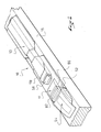
- the figures thus show a device 10 intended to ensure the attachment of a shoe 46 on a ski 15.
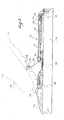
- the shoe (symbolized in phantom in FIG. 3) has the classic appearance of a cross-country ski boot 46 with a flexible sole provided on the underside of its sole with a continuous longitudinal groove and intended to to cooperate with a guide edge 18 of the fastening device 10.
- this shoe 46 has, at its front end, a transverse latching bar before 48 disposed across the groove, and behind the front bar 48, a second transverse bar 50 also disposed across the groove and located for example substantially at the region of the metatarsophalangeal joint of the foot.
- the rear bar 50 is arranged forward of the first third in length of the shoe which is substantially the rear edge of the metatarsophalangeal joint area.
- the front bar 48 is preferably made in the form of a cylindrical rod of revolution.
- the fastening device comprises at least two sub-assemblies that can be distinguished: a module 11 that incorporates a shoe retaining system, and a module 13 which incorporates an elastic return system.
- the two modules are intended to be assembled one behind the other, as shown in Figure 2, to form the fixing device.
- the retaining module is arranged at the front of the device and is arranged on an upper face of the ski.
- the retaining module 11 may be an independent pre-assembled subassembly simply attached to the ski, but it can also be provided that it is at least partly integrated in the ski.
- this retaining module 11 comprises in particular a base 110 which forms a main body of the retaining subassembly and which is intended to be fixed on the ski, for example by screws.
- the retaining system comprises a hook-shaped front jaw 52, which is movable longitudinally relative to the base and which is controlled by an opening / closing lever 54, which is articulated to the front end of the retaining module.
- a transverse edge 56 of the base is arranged just on the edge of the movable jaw 52 and is a fixed jaw to ensure, when the movable jaw is in a retracted locking position, the locking of the front bar 48 of the shoe 46.
- the shoe is restraint on the sports article with a possibility to move, in relation to the sports article, according to a rotational movement about the axis of the bar 48, between a low position in which the sole of the shoe is in support of the sports article, and a high position in which the heel is off the sports article.
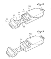
- the lever 54 is pivotally lifted as shown in Fig. 7, the movable jaw 52 is moved longitudinally (forwardly in the illustrated embodiment), causing the restraint system to open, so as to allow engaging or disengaging the front bar 48 of the shoe.
- the fixing device 10 comprises an elastic return system of the shoe to its lower position which is intended to cooperate with the rear bar 50 of the shoe.
- this elastic return system is integrated with a pre-assembled autonomous module 13 which is fixed on the sports article at least partially independently of the rest of the fixing device, and in particular compared to the restraint system.
- this pre-assembled module integrates several components that are linked to each other to provide a powerful elastic return function.
- the elastic return system and the corresponding module may take various forms, in particular derived from the system described in EP-768.103.
- the elastic return system illustrated in the figures comprises at least one elastic member 20 which is directly or indirectly linked to the sports article, and a flexible link 30 which connects the elastic member to the shoe 46 and which cooperates with at least one return member 34.
- the flexible link 30 is linked to the shoe directly, by a hook 58.
- the invention could also be applied to the case of a fixing device in which the elastic return system is indirectly connected to the shoe, via a connecting member, as seen in the preamble.
- the fixing device 10 comprises a guide edge 18 which is formed of a section of parallelepipedal or trapezoidal section and extends longitudinally rearwardly behind the retaining system.
- this guide edge 18 is provided to cooperate with a groove of complementary section arranged in the sole of the shoe to ensure lateral guidance of the shoe / fastening assembly.
- This guide edge is formed by the geometry of a main body 130 forming a base of the rear return module 13.
- the elastic member 20 is a tension spring which is arranged horizontally and longitudinally in the housing 22.
- the elastic member 20 is connected by a rear end to the base of the return module 13, and, at its front end, to the flexible link 30 which extends forwardly.
- the flexible link 30 is provided at its front end with a hook 58, for example made of metal or plastic.
- the hook may be overmolded on the front end of the flexible link so as to ensure a perfectly reliable anchorage.
- the hook 58 protrudes outside the housing 22, at the front end of the return module 13, and is intended to hook onto the rear bar 50 of the boot. , to ensure the connection of the elastic member 20 to the shoe 46, and thus allow the system to perform its elastic return function.
- the flexible link 30 passes under a reference 34 (for example made in the form of a pulley or a curved surface) which is here arranged at the front opening of the housing 22, and which is therefore carried by the module recall 13.
- a reference 34 for example made in the form of a pulley or a curved surface
- the operation of the return system when the shoe is attached to the device is as follows. If the user lifts the heel of the boot, the latter rotates about the axis of the hinge materialized by the front bar 48. At the same time, the rear bar 50 raises in a substantially arcuate trajectory of a circle and, as illustrated in Figure 3, carries with it the hook 58, which causes, through the flexible link 30 (which is supported on the return 34), the elongation of the spring 20.
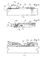
- the fixing device comprises a mechanism that moves the hook between a rest position shown in Figure 6 and an unobstructed waiting position as shown in Figure 7.
- the return module comprises a slide 74 which is mounted to move in translation in the longitudinal direction at the front end of the housing 22, thus at the front end of the module 13, as illustrated in FIGS. 8 and 9. .
- the hook 58 On its side, the hook 58 comprises a guide portion 60 which is intended to cooperate with complementary surfaces arranged at the front end of the slide 74.
- the hook 58 is guided and held in this predetermined position by the cooperation of its guide portion 60 and associated forms of the slide 74.
- These forms complementary means determine not only a precise longitudinal position of the hook with respect to the slider 74 (and thus also by relative to the main body of the module 13), but they also preferably provide a transverse lock and a locking height of the hook.
- the slider 74 is traversed longitudinally by the flexible link 30, and it can be seen that the flexible link passes beneath a curved surface carried by the slider 74, this curved surface forming the return 34 of which it has been mentioned above.
- the retention system of the fixing device comprises a slide 62, a front portion of which is connected to the movable jaw 52 to follow the longitudinal movements, which are controlled by the lever 54.
- the slide 62 advances longitudinally along with the movable jaw 52.
- the drawer 62 has a rear portion 64 which , in the retracted position of the slide 62, extends inside the opening opening of the housing 22, under the slide 74.
- This rear portion 64 of the drawer 62 has a notch 65 which, when the two subassemblies of the binding are assembled on the ski, is housed behind a rear edge 75 of the slide 74 so that when the slide 62 is controlled towards the front (when the user raises the lever 54, to open the restraint system), the drawer 62 drives with it forwards the slide 74, from its rest position to its unobstructed standby position.
- the hook 58 is more likely to cooperate with the rear bar 50 of the shoe, which can then be put in place (or otherwise removed). This is done by engaging the front bar 48 of the sole between the two jaws 52, 54 of the hinge, and then pivoting down the sole of the shoe 46 about the axis formed by the hinge.
- the rear bar 50 has reached a position in which it is likely to be hooked by the hook 58.
- the user can close the binding by lowering the lever 54, which has the effect of locking the jaws of the hinge around the front bar 48.
- the heaving operation is carried out in the opposite direction of the installation.
- the user opens the binding by raising the lever 54 which causes on the one hand the opening of the jaws 52, 56, and on the other hand the advanced drawer 62.
- the latter by its rear portion 64, drives the slide 74 and the hook 58 forward, which releases the rear bar 50 of the shoe.
- the boot can be carried out in another manner, benefiting from the ramp shape of the upper face of the hook 58.
- the hook 58 can not catch on the rear bar 50.
- the shoe is then locked so as to be able to perform a movement in an arc around the axis of the front bar 48.
- the user will bring the rear bar 50 in contact with the upper face of the hook which is then in the rest position. Under the effect of the weight of the user, the rear bar cooperates with the ramp shape of the hook 58 to advance it, against the elastic return force, to allow snapping by simple snap.
- the flexible link 30 is substantially inextensible. It may for example be a wire rope or a fiber cable with very low extensibility, for example an aramid fiber cable. It can also be envisaged that this link is made in the form of a band. This traction band may for example be made in the form of a metal strip, or a bundle of parallel fibers embedded in a polymeric material.
- the link is sufficiently flexible and flexible not to provide a noticeable elastic effect, and especially to support an angle of about 90 degrees. It thus appears that the flexibility of the link 30 is to be appreciated mainly as flexural flexibility around the axis of the return. This flexibility of the link can not be local only, because the link moves with respect to the return.
- a flexible link is a band
- said band will not be flexible in bending around an axis perpendicular to the plane of the band, but this will not prevent this band from being considered flexible within the meaning of the invention if it does not offer significant resistance to bending around the return axis.
- the reminder system may be advantageous to provide the reminder system with an adjustment mechanism, so as to allow the user the possibility of increasing or decreasing the intensity of the elastic return force for the adapt to his style of sport practice.
- the adjustment mechanism simply plays on the stiffness of the elastic member, imposing a more or less significant prestressing.
- the rear end of the spring is hooked on a ring 84 which is mounted in the housing 22 on a screw 40, while being locked in rotation about the axis of the screw.
- the rear end of the screw 40 protrudes outside the housing 22 and has the shape of a screw head 42 so as to allow the user to control the rotation of the screw 40 about its axis.
- the guide edge 18 has a window which would allow the user to view the position of the ring and that would allow him to evaluate the value of prestressing of the spring. At this window could be associated with graphical markers.
- This elastic return system is particularly interesting because it allows to accommodate the elastic member in an area of the device where it does not interfere with the kinematics and the roll of foot allowed by the fixation.
- the elastic return module is arranged behind the restraint system, but it could also be expected that it is arranged in front of it.
- the return system provides a restoring force is perfectly controlled, especially because the retention of the shoe is performed by an independent system. It can thus be expected that the beginning of the uprising is done with a low initial return effort, then "program" the evolution curve of this effort depending on the lifting angle of the shoe.
- the elastic member may consist of several springs in series and / or in parallel, and / or it may also incorporate elastomeric elements having another type of stress / strain curve.
- the elastic return system may be supplemented by other elastic systems or stop systems.
- This abutment 82 may be a rigid abutment which limits the stroke of the boot, or a resilient abutment made in the form of an elastic buffer of the type described in document FR-A-2,650,192, which will then at the same time time a soft abutment effect and an additional elastic return force.
- the abutment 82, rigid or elastic, can cooperate directly with the shoe.
- This stop 82 is intended to introduce a marker element by which the user can "recognize” or "feel” a reference position in the movement of his foot relative to the sporting article.
- the stop 82 illustrated in the figures is fixed, but it could be expected that its longitudinal position is adjustable by the user, especially so that it can adapt the reference position to the length of his stride.
- the stop will provide a restoring force complementary to that of the main return system.
- the holding module 11 comprises in particular a main body which forms a base 110, a movable body 112 which forms both the movable jaw 52 and the slide 62, the lever 54 which is articulated on the movable body, and a rod 114 which, as seen in Figure 7, is articulated by its front end on the main body 110 and its rear end on the lever 54.
- the main body 110 of the retaining module 11 has a rear extension 116 which extends behind the fixed jaw portion 56 and which has an arch 118.
- the rear extension terminates in a rear plate which is provided with a orifice for the passage of a screw 119, allowing the attachment of this main body 110 on the upper face of the ski.
- the rear extension 116 is illustrated more particularly in FIG. 4, where it can also be seen that the rear end 64 of the drawer is intended to extend behind the arch 118, but in front of the rear plate in which the hole for the fixing screw 119. is arranged.
- the main body 110 also has other fixing means arranged in its front part, but which are not shown here.
- this retaining module assembly 11 is pre-assembled to form a unitary subassembly of the fastener.
- the return module 13 comprises a main body 130 which also forms a base by which the return module 13 is at least partly fixed on the ski.
- This main body thus has an axial portion in the form of a hollow beam 132 which forms, on the outside, the guide edge 18 and, inside, the housing 22.
- this axial beam 132 is lined transversely on both sides by two horizontal flanges 134 intended to bear on the upper surface of the ski.
- Figure 1 there is shown the possibility that the axial beam 132 has, at its rear end, a passage opening 136 of a screw for participating in the fixing of the return module 13 on the ski. This orifice is advantageously masked by a cover.
- the return module 13 which comprises in particular the main body 130, the spring 20, the flexible link 30, the hook 58 and the slider 74, is pre-assembled to form a unitary subassembly of the fixing device 10, as shown in FIG. 5.
- FIG. 6 it is shown in detail how the return module 13 is mounted behind the retaining module 11. It can be seen that the nose 138 of the return module is engaged below the arch 118 which provides thus blocking upwards and in the transverse direction. However, we also see that the hook 58 protrudes ahead of the arch 118. At the same time, we see how, when engaging the nose 138 of the return module 13 under the arch 118, we will ensure proper positioning of the slider 74 in front of the notch 65 of the rear end 64 of the slide 65, in order to ensure a meshing effect between the notch 65 and the rear edge 75 of the slider 74 when the restraint system 11 and the control system resilient return 13 are arranged on the sports article.
- the arch 118 of the retaining module 11 partially ensures the fixing of the return module 13, this fixing being completed by the fact that the main body 130 of this booster module, which is resting on the upper face of the ski, is also directly attached to the ski, by its rear part, through a screw screwed through the orifice 136.
- This solution by which the unitary elastic return module is fixed in a way that is only partly independent on the sports article, makes it possible to simplify the assembly of the reminder module 13. However, it could also provide that the fixing of the return module is completely independent of that of the retaining module.
- the return module 13 covers and hides the rear plate of the extension 116, thus hiding the fixing screw 119. It can be seen that the design of the device into two autonomous sub-assemblies makes it possible to arranging a fixing means substantially in the middle of the device, in an area which, once the return module in place, is no longer accessible. In a one-part construction, such an arrangement of the fastening means would be problematic, for simple reasons of lack of accessibility to the fastening means.
- the fixing device according to the invention is therefore designed such that the elastic return module can be removed from the sports article independently of the restraint system.
- the elastic return module can be replaced with another, of the same type (for example when a part of the return module breaks), or of a different type.
- the same restraint system can be used with return modules incorporating elastic members of very different stiffness.
- the booster modules use different resilient return systems. It is indeed possible to provide an autonomous return module on the basis of the elastic return system rod as described in the prior art EP-768.103.
- a retraction module fastening device can thus make it possible to standardize the retaining system between two types of fastening, leaving a greater possibility of choice for the user and / or allowing the manufacturer to produce these systems with fasteners. advantageous costs.
Landscapes
- Footwear And Its Accessory, Manufacturing Method And Apparatuses (AREA)
- Sealing Devices (AREA)
Applications Claiming Priority (1)
| Application Number | Priority Date | Filing Date | Title |
|---|---|---|---|
| FR0407834A FR2873044B1 (fr) | 2004-07-13 | 2004-07-13 | Dispositif de fixation d'une chaussure a un article de sport avec systeme de rappel elastique separe |
Publications (1)
| Publication Number | Publication Date |
|---|---|
| EP1616604A1 true EP1616604A1 (de) | 2006-01-18 |
Family
ID=34950829
Family Applications (1)
| Application Number | Title | Priority Date | Filing Date |
|---|---|---|---|
| EP05012827A Withdrawn EP1616604A1 (de) | 2004-07-13 | 2005-06-15 | Bindungsanlage für einen Schuh an einem Sportgerät mit getrennten elastischen Rückstellmitteln |
Country Status (5)
| Country | Link |
|---|---|
| US (1) | US7644947B2 (de) |
| EP (1) | EP1616604A1 (de) |
| FR (1) | FR2873044B1 (de) |
| NO (1) | NO327572B1 (de) |
| RU (1) | RU2372126C2 (de) |
Cited By (1)
| Publication number | Priority date | Publication date | Assignee | Title |
|---|---|---|---|---|
| RU2621777C2 (ru) * | 2015-10-27 | 2017-06-07 | Роман Владимирович Шамов | Лыжное крепление р.в. шамова |
Families Citing this family (19)
| Publication number | Priority date | Publication date | Assignee | Title |
|---|---|---|---|---|
| USD538372S1 (en) * | 2004-12-03 | 2007-03-13 | Salomon S.A. | Ski binding |
| WO2007127969A2 (en) * | 2006-04-28 | 2007-11-08 | Lane Ekberg | Pivoting footwear systems and, configurable traction systems |
| USD627027S1 (en) | 2006-09-15 | 2010-11-09 | Salomon S.A.S. | Ski binding |
| US20080184599A1 (en) * | 2006-10-10 | 2008-08-07 | Lane Ekberg | Pivoting footwear systems and, configurable traction systems |
| USD617408S1 (en) | 2007-12-13 | 2010-06-08 | Salomon S.A.S. | Ski binding |
| FR2946545B1 (fr) * | 2009-06-16 | 2011-07-15 | Salomon Sas | Fixation pour ski et ski associe |
| FR2946505B1 (fr) * | 2009-06-16 | 2011-11-18 | Salomon Sas | Chaussure pour ski |
| NO20101289A1 (no) * | 2010-09-15 | 2012-03-16 | Rottefella As | Langrennsbinding, samt fremgangsmate for sammenstilling av nevnte langrennsbinding |
| FR2969004B1 (fr) * | 2010-12-17 | 2013-02-08 | Salomon Sas | Article de sport avec guide chaussure |
| RU2520540C2 (ru) * | 2012-06-26 | 2014-06-27 | Владимир Александрович Шамов | Головная часть лыжного крепления |
| RU2520539C2 (ru) * | 2012-06-26 | 2014-06-27 | Владимир Александрович Шамов | Головка лыжного крепления |
| RU2503476C1 (ru) * | 2012-06-26 | 2014-01-10 | Владимир Александрович Шамов | Головная часть лыжного крепления |
| RU2518170C2 (ru) * | 2012-07-02 | 2014-06-10 | Владимир Александрович Шамов | Головная часть лыжного крепления |
| EP2898931A1 (de) * | 2014-01-24 | 2015-07-29 | Technische Universität München | Skibindung mit vorfußfixierendem Modul |
| RU2541747C1 (ru) * | 2014-04-23 | 2015-02-20 | Роман Владимирович Шамов | Лыжное крепление |
| USD820932S1 (en) | 2016-05-04 | 2018-06-19 | Salomon S.A.S. | Ski binding |
| USD820933S1 (en) | 2016-05-04 | 2018-06-19 | Salomon S.A.S. | Ski binding |
| RU2650073C1 (ru) * | 2017-04-17 | 2018-04-06 | Роман Владимирович Шамов | Фиксирующий механизм с зацепом для скобы ботинка |
| RU2650072C1 (ru) * | 2017-04-17 | 2018-04-06 | Роман Владимирович Шамов | Фиксирующий механизм с зацепом для скобы ботинка |
Citations (11)
| Publication number | Priority date | Publication date | Assignee | Title |
|---|---|---|---|---|
| US3863942A (en) | 1972-08-16 | 1975-02-04 | Wunder Kg Heinrich | Ski binding |
| NL8602796A (nl) * | 1986-11-05 | 1988-06-01 | Peter Brinckman | Schaats. |
| FR2652754A1 (fr) * | 1989-10-11 | 1991-04-12 | Salomon Sa | Dispositif de guidage lateral d'une chaussure de ski de fond. |
| DE4143410A1 (de) * | 1991-12-20 | 1993-07-08 | Silvretta Sherpas Sportartikel | Sicherheitsbindung |
| WO1996037269A1 (en) | 1995-05-24 | 1996-11-28 | Gierveld Beheer B.V. | Sport device |
| EP0768103A1 (de) | 1995-10-16 | 1997-04-16 | Salomon S.A. | Schuh-Bindungseinheit an einem Ski |
| EP0890379A1 (de) | 1997-07-07 | 1999-01-13 | Fritschi AG - Swiss Bindings | Skibindung |
| WO1999002226A1 (en) | 1997-07-11 | 1999-01-21 | Harold Edward Ayliffe | Pre-compressed spring ski binding |
| EP0914844A1 (de) | 1997-11-06 | 1999-05-12 | Stylus S.P.A. | Schlittschuh |
| WO2000013755A1 (fr) | 1998-09-02 | 2000-03-16 | Salomon S.A. | Dispositif de fixation d'une chaussure a un article de sport |
| WO2001093963A1 (de) | 2000-06-08 | 2001-12-13 | Rottefella As | Anordnung aus einer skibindung und einem skischuh |
Family Cites Families (14)
| Publication number | Priority date | Publication date | Assignee | Title |
|---|---|---|---|---|
| US2172669A (en) * | 1939-09-12 | Ski harness | ||
| FR2170808B1 (de) | 1972-02-01 | 1974-12-13 | Salomon & Fils F | |
| FR2287929A1 (fr) * | 1974-10-14 | 1976-05-14 | Mitchell Sa | Fixation de securite pour ski |
| FR2363341A1 (fr) | 1976-09-01 | 1978-03-31 | Emery Roger | Fixation de ski |
| AT368022B (de) * | 1980-09-08 | 1982-08-25 | Naepflin Hans | Skibindung mit einer sohlenplatte |
| WO1987003211A1 (fr) * | 1985-11-22 | 1987-06-04 | Tmc Corporation | Fixation de ski pour ski de fond ou de tourisme |
| FR2634132B1 (fr) | 1988-07-13 | 1992-10-23 | Salomon Sa | Dispositif de fixation notamment pour chaussure de ski de fond |
| FR2650192B1 (fr) | 1989-07-28 | 1991-10-25 | Salomon Sa | Fixation pour ski de fond et tampon elastique destine a une telle fixation |
| DE4010929A1 (de) * | 1990-04-04 | 1991-10-10 | Walter Dekanovsky | Langlaufskibindung |
| US6374517B2 (en) | 1994-04-29 | 2002-04-23 | Salomon S.A. | Sole for a sport boot and a sport boot including such sole |
| FR2719229B1 (fr) * | 1994-04-29 | 1996-06-28 | Salomon Sa | Dispositif de fixation d'une chaussure à un ski de fond. |
| FR2850031B1 (fr) * | 2003-01-21 | 2006-08-11 | Salomon Sa | Fixation a energie deportee |
| FR2856312B1 (fr) | 2003-06-18 | 2005-08-05 | Salomon Sa | Dispositif de fixation a bras pivotant |
| JP2006211296A (ja) | 2005-01-28 | 2006-08-10 | Sony Corp | マイクロマシンの製造方法およびマイクロマシン |
-
2004
- 2004-07-13 FR FR0407834A patent/FR2873044B1/fr not_active Expired - Fee Related
-
2005
- 2005-06-15 EP EP05012827A patent/EP1616604A1/de not_active Withdrawn
- 2005-07-07 US US11/175,150 patent/US7644947B2/en not_active Expired - Fee Related
- 2005-07-12 NO NO20053379A patent/NO327572B1/no not_active IP Right Cessation
- 2005-07-12 RU RU2005122071/12A patent/RU2372126C2/ru not_active IP Right Cessation
Patent Citations (11)
| Publication number | Priority date | Publication date | Assignee | Title |
|---|---|---|---|---|
| US3863942A (en) | 1972-08-16 | 1975-02-04 | Wunder Kg Heinrich | Ski binding |
| NL8602796A (nl) * | 1986-11-05 | 1988-06-01 | Peter Brinckman | Schaats. |
| FR2652754A1 (fr) * | 1989-10-11 | 1991-04-12 | Salomon Sa | Dispositif de guidage lateral d'une chaussure de ski de fond. |
| DE4143410A1 (de) * | 1991-12-20 | 1993-07-08 | Silvretta Sherpas Sportartikel | Sicherheitsbindung |
| WO1996037269A1 (en) | 1995-05-24 | 1996-11-28 | Gierveld Beheer B.V. | Sport device |
| EP0768103A1 (de) | 1995-10-16 | 1997-04-16 | Salomon S.A. | Schuh-Bindungseinheit an einem Ski |
| EP0890379A1 (de) | 1997-07-07 | 1999-01-13 | Fritschi AG - Swiss Bindings | Skibindung |
| WO1999002226A1 (en) | 1997-07-11 | 1999-01-21 | Harold Edward Ayliffe | Pre-compressed spring ski binding |
| EP0914844A1 (de) | 1997-11-06 | 1999-05-12 | Stylus S.P.A. | Schlittschuh |
| WO2000013755A1 (fr) | 1998-09-02 | 2000-03-16 | Salomon S.A. | Dispositif de fixation d'une chaussure a un article de sport |
| WO2001093963A1 (de) | 2000-06-08 | 2001-12-13 | Rottefella As | Anordnung aus einer skibindung und einem skischuh |
Cited By (1)
| Publication number | Priority date | Publication date | Assignee | Title |
|---|---|---|---|---|
| RU2621777C2 (ru) * | 2015-10-27 | 2017-06-07 | Роман Владимирович Шамов | Лыжное крепление р.в. шамова |
Also Published As
| Publication number | Publication date |
|---|---|
| NO20053379D0 (no) | 2005-07-12 |
| FR2873044A1 (fr) | 2006-01-20 |
| FR2873044B1 (fr) | 2006-09-29 |
| NO327572B1 (no) | 2009-08-17 |
| RU2372126C2 (ru) | 2009-11-10 |
| US20060012151A1 (en) | 2006-01-19 |
| NO20053379L (no) | 2006-01-16 |
| US7644947B2 (en) | 2010-01-12 |
| RU2005122071A (ru) | 2007-01-20 |
Similar Documents
| Publication | Publication Date | Title |
|---|---|---|
| EP1440713B1 (de) | Bindung mit versetzter Energie | |
| EP1616604A1 (de) | Bindungsanlage für einen Schuh an einem Sportgerät mit getrennten elastischen Rückstellmitteln | |
| EP1839713B1 (de) | Einheit aus einem Langlaufski und einer Langlaufbindung | |
| EP1488831B1 (de) | Bindung mit einem Schwenkarm | |
| FR2739788A1 (fr) | Ensemble de fixation d'une chaussure a un organe de glisse | |
| EP2486817B1 (de) | Sportschuh mit angelenktem Schaft für eine Laufstellung | |
| FR2640516A1 (fr) | Fixation de securite pour ski destinee a maintenir, de facon declenchable, l'avant d'une chaussure montee sur le ski | |
| EP0769977A1 (de) | Sicherheitsbindung für telemarkskis, tourenskis und sprungskis | |
| EP2769755B1 (de) | Vordere Halteeinrichtung mit automatischer Auslösung bei Verdrehung | |
| EP0241360B1 (de) | Sicherheitsskibindung | |
| FR2660569A1 (fr) | Fixation pour ski de fond. | |
| FR2741543A1 (fr) | Fixations pour ski de fond | |
| FR2802108A1 (fr) | Dispositif de retenue d'une chaussure sur une planche de glisse | |
| FR2654636A1 (en) | Multipurpose device for mounting a boot on a ski | |
| EP2552559A1 (de) | Bindung zum üben von skilaufen | |
| CH673400A5 (de) | ||
| EP1027908A1 (de) | Rückhaltesystem für Schuhe auf Skier | |
| EP0544063B1 (de) | Sicherheitsbindung für Alpinski | |
| EP0820789B1 (de) | Schuh-Ski Kombination | |
| EP1721641B1 (de) | Bindungsvorrichtung mit einstellbarer Rückhubenergie | |
| EP0648439A1 (de) | Schischuh | |
| EP1608444A2 (de) | Schuhbindung mit einem zweiteiligen verbindungsorgan | |
| FR2631244A1 (fr) | Machoire anterieure equipant des fixations de securite pour skis | |
| EP1559456B1 (de) | skibindung mit integrierter auslösung | |
| EP0495737B1 (de) | Skibremse |
Legal Events
| Date | Code | Title | Description |
|---|---|---|---|
| PUAI | Public reference made under article 153(3) epc to a published international application that has entered the european phase |
Free format text: ORIGINAL CODE: 0009012 |
|
| AK | Designated contracting states |
Kind code of ref document: A1 Designated state(s): AT BE BG CH CY CZ DE DK EE ES FI FR GB GR HU IE IS IT LI LT LU MC NL PL PT RO SE SI SK TR |
|
| AX | Request for extension of the european patent |
Extension state: AL BA HR LV MK YU |
|
| 17P | Request for examination filed |
Effective date: 20060329 |
|
| AKX | Designation fees paid |
Designated state(s): AT BE BG CH CY CZ DE DK EE ES FI FR GB GR HU IE IS IT LI LT LU MC NL PL PT RO SE SI SK TR |
|
| RAP1 | Party data changed (applicant data changed or rights of an application transferred) |
Owner name: SALOMON S.A.S. |
|
| 17Q | First examination report despatched |
Effective date: 20100126 |
|
| STAA | Information on the status of an ep patent application or granted ep patent |
Free format text: STATUS: THE APPLICATION IS DEEMED TO BE WITHDRAWN |
|
| 18D | Application deemed to be withdrawn |
Effective date: 20140103 |