EP1616801A2 - Becher - Google Patents
Becher Download PDFInfo
- Publication number
- EP1616801A2 EP1616801A2 EP05291521A EP05291521A EP1616801A2 EP 1616801 A2 EP1616801 A2 EP 1616801A2 EP 05291521 A EP05291521 A EP 05291521A EP 05291521 A EP05291521 A EP 05291521A EP 1616801 A2 EP1616801 A2 EP 1616801A2
- Authority
- EP
- European Patent Office
- Prior art keywords
- skeletal member
- shaped container
- cup shaped
- ring
- columnar
- Prior art date
- Legal status (The legal status is an assumption and is not a legal conclusion. Google has not performed a legal analysis and makes no representation as to the accuracy of the status listed.)
- Granted
Links
Images




Classifications
-
- B—PERFORMING OPERATIONS; TRANSPORTING
- B65—CONVEYING; PACKING; STORING; HANDLING THIN OR FILAMENTARY MATERIAL
- B65D—CONTAINERS FOR STORAGE OR TRANSPORT OF ARTICLES OR MATERIALS, e.g. BAGS, BARRELS, BOTTLES, BOXES, CANS, CARTONS, CRATES, DRUMS, JARS, TANKS, HOPPERS, FORWARDING CONTAINERS; ACCESSORIES, CLOSURES, OR FITTINGS THEREFOR; PACKAGING ELEMENTS; PACKAGES
- B65D3/00—Rigid or semi-rigid containers having bodies or peripheral walls of curved or partially-curved cross-section made by winding or bending paper without folding along defined lines
- B65D3/02—Rigid or semi-rigid containers having bodies or peripheral walls of curved or partially-curved cross-section made by winding or bending paper without folding along defined lines characterised by shape
- B65D3/06—Rigid or semi-rigid containers having bodies or peripheral walls of curved or partially-curved cross-section made by winding or bending paper without folding along defined lines characterised by shape essentially conical or frusto-conical
-
- B—PERFORMING OPERATIONS; TRANSPORTING
- B65—CONVEYING; PACKING; STORING; HANDLING THIN OR FILAMENTARY MATERIAL
- B65D—CONTAINERS FOR STORAGE OR TRANSPORT OF ARTICLES OR MATERIALS, e.g. BAGS, BARRELS, BOTTLES, BOXES, CANS, CARTONS, CRATES, DRUMS, JARS, TANKS, HOPPERS, FORWARDING CONTAINERS; ACCESSORIES, CLOSURES, OR FITTINGS THEREFOR; PACKAGING ELEMENTS; PACKAGES
- B65D11/00—Containers having bodies formed by interconnecting or uniting two or more rigid, or substantially rigid, components made wholly or mainly of plastics material
- B65D11/02—Containers having bodies formed by interconnecting or uniting two or more rigid, or substantially rigid, components made wholly or mainly of plastics material of curved cross-section
-
- B—PERFORMING OPERATIONS; TRANSPORTING
- B65—CONVEYING; PACKING; STORING; HANDLING THIN OR FILAMENTARY MATERIAL
- B65D—CONTAINERS FOR STORAGE OR TRANSPORT OF ARTICLES OR MATERIALS, e.g. BAGS, BARRELS, BOTTLES, BOXES, CANS, CARTONS, CRATES, DRUMS, JARS, TANKS, HOPPERS, FORWARDING CONTAINERS; ACCESSORIES, CLOSURES, OR FITTINGS THEREFOR; PACKAGING ELEMENTS; PACKAGES
- B65D3/00—Rigid or semi-rigid containers having bodies or peripheral walls of curved or partially-curved cross-section made by winding or bending paper without folding along defined lines
- B65D3/28—Other details of walls
- B65D3/30—Local reinforcements, e.g. metallic rims
Definitions
- the present invention relates to a cup shaped container for storing beverage liquids such as juice, confectioneries and industrial materials.
- the cup disclosed in, for example, Japanese Laid-Open Patent Publication No. 9-207936 is known. That is, the cup shaped container in which a blank sheet is wrapped around and attached to a skeletal member made from a synthetic resin is known.
- a skeletal member used in a cup shaped container disclosed in Japanese Laid-Open Patent Publication No. 9-207936 includes a bottom part, an upper edge part, and columnar parts for connecting the bottom part and the upper edge part, and the cup shaped container is configured by wrapping the blank sheet around the skeletal member.
- the skeletal member used in the cup shaped container disclosed in Japanese Laid-Open Patent Publication No. 9-207936 includes the bottom part, the upper edge part, and the columnar parts for connecting the bottom part and the upper edge part, and the cup shaped container formed by wrapping the blank sheet around the skeletal member is disposed in its original shape after use.
- the columnar parts of the skeletal member used in the cup shaped container are formed so as to have the same thickness throughout, and thus the cup shaped container cannot be compressed in the up and down direction by hand, and must be thrown away in its full dimension state.
- the present invention has an object to provide a cup shaped container that can be squashed by hand so as to become compact when disposing after use.
- a cup shaped container characterized as follows.
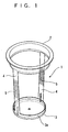
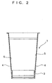
- Figs. 1 to 6 show the first embodiment of the present invention.
- reference character 1 refers to a skeletal member including a circular ring-like part 2 at the upper end, a shallow saucer-like circular bottom part 3 at the lower end, and left and right columnar parts 4 for connecting the ring-like part 2 and the bottom part 3.
- Each columnar part 4 has an indented part 5 formed on the inner surface in the vicinity of the central part thereof for the full width of the columnar part 4.
- Each indented part 5 has protrusions and depressions formed at an equally spaced pitch, more specifically at a few mm pitch, and extends in the up and down direction for a length range of about a few cm.
- the skeletal member 1 is made from a synthetic resin material such as polypropylene, polyethylene, nylon, polyester and the like, and can be molded to a desired hardness by changing the thickness depending on the material used.
- Reference character 6 refers to a flexible blank sheet that is attached to the skeletal member 1 so as to wrap a periphery of the skeletal member 1.
- the entire blank sheet 6 may be made from a synthetic resin material of the same type as the material of the skeletal member 1, or may have at least an inner surface thereof made from the synthetic resin material of the same type as the material of the skeletal member 1.
- the blank sheet 6 includes a circular sheet portion 6a that matches the shape of a back surface of the bottom part 3 of the skeletal member 1, and sheet portions 6c, 6c that are connected to both sides of the sheet portion 6a through connecting parts 6b, 6b each having a small width and that have a shape similar to a fan for covering an opening defined by the ring-like part 2, the bottom part 3 and the left and right columnar parts 4 of the skeletal member 1.
- the sheet portion 6a of the blank sheet 6 is attached to the back surface of the bottom part 3 of the skeletal member 1 by means of heat-sealing, and the periphery, more specifically the lower end of each of the sheet portions 6c, 6c is attached to an outer surface of a raised part 3a around the periphery of the bottom part 3, and the upper end is attached to the outer surface of the lower end of the ring-like part 2 around the periphery thereof. And the both sides are attached to the outer surfaces of the left and right columnar parts 4 by means of heat-sealing.
- an opening defined by the ring-like part 2, the bottom part 3 and the left and right columnar parts 4 is covered as if to wrap the periphery of the skeletal member 1.
- the cup shaped container 7 is thereby formed.
- a metal die including a core and a cavity is used in molding the cup shaped container 7, a metal die including a core and a cavity is used.
- the sheet portion 6a of the blank sheet 6 is brought into contact with the distal end of the core and sucked.
- the core is fitted into the cavity, and then a resin is poured into a space between the core and the cavity to mold the cup shaped container 7 by heat-sealing the blank sheet 6 to the skeletal member 1, as mentioned above.
- a lid body is attached to the upper end of the ring-like part 2 of the skeletal member 1 in such a fashion that the lid body can be freely separated by using fingers.
- a barrier property may be given to the cup shaped container 7, depending on the content stored in the cup shaped container 7.
- a port may be integrally formed at one part of the periphery of the ring-like part 2 to take out beverage liquid from the cup shaped container 7 without separating the lid body.
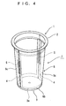
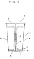
- Figs. 7 to 9 show a second embodiment of the present invention.
- the indented part 5 is formed at the central part of each of the left and right columnar parts 4 of the skeletal member 1 so as to allow the cup shaped container 7 which is unwanted after use to be squashed when disposing it.
- depressions 8 having a small width are formed in the neighborhood of the central part of each columnar part 4, more specifically at both ends of the central part and at both upper and lower ends of the central part, as viewing the columnar part 4 from the front.
- each of the columnar parts 4 is bent inward at the position of any one of the depressions 8 having a small width, by applying a force in a direction of compressing the cup shaped container 7, whereby the cup shaped container 7 is squashed to be compact.
- Other configurations are the same as those in the first embodiment. If the configuration in which the depressions 8 are formed at the columnar parts 4 as in the second embodiment is combined with the configuration in which the indented part 5 is formed at the columnar part 4 as in the first embodiment, squashing the cup shaped container 7 to be compact can be further easily carried out.
- the columnar part 4 has an indented part 5 or a depression 8 having a small width so as to squash the skeletal member 1 of the cup shaped container 7 to be compact.
- the columnar part 4 may have one or a plurality of parts reduced in thickness for the entire width thereof to exert the same function as mentioned above.
- the circular sheet portion 6a of the blank sheet 6 is attached to the back surface of the bottom part 3 of the skeletal member 1 by means of heat-sealing, but the circular sheet portion 6a may be attached to an upper surface of the bottom part 3 of the skeletal member 1.
- the blank sheet 6 may be made from a synthetic resin material of the same type as the material of the skeletal member 1, or at least the inner surface and the outer surface thereof may be made from a synthetic resin material of the same type as the material of the skeletal member 1. That is, only the joint surface of the blank sheet 6 attaching to the skeletal member 1 needs be made from the synthetic resin material of the same type as the skeletal member 1. Further, the material of the blank sheet 6 may also be paper.
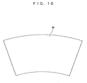
- Fig. 10 illustrates a third embodiment of the present invention showing a modification of the blank sheet 6.
- the blank sheet 6 in the first and second embodiments includes the circular sheet portion 6a that matches the shape of the back surface of the bottom part 3 of the skeletal member 1, and the sheet portions 6c, 6c having a fan like shape and connected to both sides of the sheet portion 6a through the narrow connecting parts 6b, 6b in order for covering the opening defined by the ring-like part 2, the bottom part 3 and the left and right columnar parts 4 of the skeletal member 1.
- the circular sheet portion that matches the shape of the bottom part 3 of the skeletal member 1 may be omitted, and a single blank sheet 6A may be used for wrapping the entire periphery between the ring-like part 2 and the bottom part 3 at the lower end of the skeletal member 1.
- Fig. 11 illustrates a fourth embodiment showing a modification of the skeletal member 1.
- protrusions 5a of one of the columnar parts 4 and protrusions 5a of the other columnar part 4 respectively positioned at the same level in height may be integrally connected for reinforcement with a thin connecting part 5b that forms a circular arc shape along the inner periphery of the cup shaped container as shown in Fig. 11 that illustrates the fourth embodiment.
- a thin connecting part 5b that forms a circular arc shape along the inner periphery of the cup shaped container as shown in Fig. 11 that illustrates the fourth embodiment.
- the protrusions 5a positioned at the upper and lower ends and at the middle of the indented part 5 formed at the central part in the up and down direction of one the columnar part 4 are integrally connected with the equivalent protrusions 5a of the other columnar part 4 by means of the connecting part 5b, but all the protrusions 5a may be connected likewise by means of the connecting part 5b.
- such parts of the columnar parts 4 as including no indented parts 5, that is to say the upper and lower sides of the respective indented parts 5, may be integrally connected by means of a plate shaped connecting part 5c having a circular arc shape, for reinforcement between the left and right columnar parts 4.
- the shape of the bottom surface of the cup shaped container 7 formed with the skeletal member 1 as the frame may not necessarily be planar and circular as in the embodiment shown in the drawings.
- the shape may be a polygon such as a quadrilateral or a hexagon, or an ellipse.
- the number of columnar parts 4 is not limited to two.
Landscapes
- Engineering & Computer Science (AREA)
- Mechanical Engineering (AREA)
- Details Of Rigid Or Semi-Rigid Containers (AREA)
- Containers Having Bodies Formed In One Piece (AREA)
Applications Claiming Priority (1)
| Application Number | Priority Date | Filing Date | Title |
|---|---|---|---|
| JP2004205342 | 2004-07-13 |
Publications (3)
| Publication Number | Publication Date |
|---|---|
| EP1616801A2 true EP1616801A2 (de) | 2006-01-18 |
| EP1616801A3 EP1616801A3 (de) | 2006-03-29 |
| EP1616801B1 EP1616801B1 (de) | 2008-05-07 |
Family
ID=35134696
Family Applications (1)
| Application Number | Title | Priority Date | Filing Date |
|---|---|---|---|
| EP05291521A Expired - Lifetime EP1616801B1 (de) | 2004-07-13 | 2005-07-13 | Becher |
Country Status (3)
| Country | Link |
|---|---|
| US (2) | US20060011634A1 (de) |
| EP (1) | EP1616801B1 (de) |
| DE (1) | DE602005006475D1 (de) |
Cited By (1)
| Publication number | Priority date | Publication date | Assignee | Title |
|---|---|---|---|---|
| CH715480A1 (de) * | 2018-10-30 | 2020-04-30 | Alpla Werke Alwin Lehner Gmbh & Co Kg | Kunststoffbehälter insbesondere für fliess- und rieselfähiges Füllgut, wobei der Behälterkörper wenigstens eine Stützstruktur aufweist. |
Families Citing this family (14)
| Publication number | Priority date | Publication date | Assignee | Title |
|---|---|---|---|---|
| US8556099B2 (en) | 2010-06-11 | 2013-10-15 | Diane Perlman | Collapsible cup for zero waste applications |
| EP2418065A1 (de) * | 2010-08-09 | 2012-02-15 | Nestec S.A. | Spritzgussetikettierter Behälter |
| USD721926S1 (en) * | 2013-04-09 | 2015-02-03 | Giftburg Enterprises Ltd. | Scroll cup |
| US9302832B2 (en) * | 2013-05-29 | 2016-04-05 | Greater Good, Inc. | Compostable container with elongate connector |
| US10532872B2 (en) * | 2014-12-08 | 2020-01-14 | Berry Plastics Corporation | Package |
| US10477998B2 (en) | 2016-03-01 | 2019-11-19 | Berry Plastics Corporation | Drink cup |
| USD845394S1 (en) * | 2016-08-26 | 2019-04-09 | Brad Max | Desktop game |
| USD851998S1 (en) | 2017-02-28 | 2019-06-25 | Berry Plastics Corporation | Portion of a drink cup |
| FR3091856B1 (fr) * | 2019-01-22 | 2020-12-25 | Hebert P | Emballage rigide et procédé de fabrication de cet emballage |
| CN115605403A (zh) * | 2020-03-17 | 2023-01-13 | 耐普罗有限公司(Us) | 融合包装 |
| WO2021214002A1 (en) * | 2020-04-20 | 2021-10-28 | Berry Superfos Randers A/S | Hybrid package and method associated |
| GB202005709D0 (en) * | 2020-04-20 | 2020-06-03 | Obrist Closures Switzerland | Jar |
| EP4705199A1 (de) * | 2023-05-05 | 2026-03-11 | Berry Global, Inc. | Behälter für verpackung |
| CN118270347A (zh) * | 2024-04-22 | 2024-07-02 | 台州市宁泽越泰模塑科技有限公司 | 一种新型包装盒及其生产工艺 |
Citations (1)
| Publication number | Priority date | Publication date | Assignee | Title |
|---|---|---|---|---|
| JPH09207936A (ja) | 1996-01-30 | 1997-08-12 | Dainippon Printing Co Ltd | 包装容器 |
Family Cites Families (17)
| Publication number | Priority date | Publication date | Assignee | Title |
|---|---|---|---|---|
| US639822A (en) * | 1899-03-24 | 1899-12-26 | Albert Mueller | Water-pail. |
| US1091908A (en) * | 1913-04-22 | 1914-03-31 | Allen C Benners | Carrier for paper and like receptacles. |
| US1530256A (en) * | 1922-02-25 | 1925-03-17 | Edith M Garland | Cup holder |
| US2755838A (en) * | 1953-12-31 | 1956-07-24 | Jr Merritt T Kennedy | Pail |
| US3032249A (en) * | 1960-11-18 | 1962-05-01 | Irene M Kollar | Tubular cooking container |
| US4026435A (en) * | 1975-07-24 | 1977-05-31 | Hendon Joseph S | Disposable cookware |
| US4211339A (en) * | 1976-12-13 | 1980-07-08 | Onoda Cement Co., Ltd. | Laminated paper container with sealed seams |
| US4109692A (en) * | 1977-06-30 | 1978-08-29 | Brown Roland H | Encapsulating device for gas cylinder |
| US4153196A (en) * | 1977-09-01 | 1979-05-08 | Champion International Corporation | Tub-shaped carton and blank for forming same |
| JP3012092B2 (ja) * | 1991-11-06 | 2000-02-21 | 臼井 芳雄 | 圧潰性缶 |
| CN2113648U (zh) * | 1992-03-26 | 1992-08-26 | 何晓亮 | 组合可折叠式置衣物箱 |
| CH685989A5 (de) * | 1992-05-12 | 1995-11-30 | Erfis Ag | Zusammenfaltbares Gebilde, insbesondere Beholtnis. |
| US5671858A (en) * | 1996-09-11 | 1997-09-30 | Ching Feng Blinds Co., Ltd. | Collapsible laundry container structure |
| GB0229178D0 (en) * | 2002-12-13 | 2003-01-22 | Worlds Apart Ltd | Storage device |
| US20040173611A1 (en) * | 2003-01-06 | 2004-09-09 | Azad Sabounjian | Collapsible container |
| CA2445553A1 (en) * | 2003-10-17 | 2004-03-10 | Stackteck Systems Limited | Semi-molded thin wall container configuration and method |
| US20050284866A1 (en) * | 2004-06-26 | 2005-12-29 | Oakner Stuart P | Disposable trash container |
-
2005
- 2005-07-01 US US11/173,610 patent/US20060011634A1/en not_active Abandoned
- 2005-07-13 EP EP05291521A patent/EP1616801B1/de not_active Expired - Lifetime
- 2005-07-13 DE DE602005006475T patent/DE602005006475D1/de not_active Expired - Lifetime
- 2005-07-13 US US11/180,761 patent/US7665627B2/en not_active Expired - Fee Related
Patent Citations (1)
| Publication number | Priority date | Publication date | Assignee | Title |
|---|---|---|---|---|
| JPH09207936A (ja) | 1996-01-30 | 1997-08-12 | Dainippon Printing Co Ltd | 包装容器 |
Cited By (2)
| Publication number | Priority date | Publication date | Assignee | Title |
|---|---|---|---|---|
| CH715480A1 (de) * | 2018-10-30 | 2020-04-30 | Alpla Werke Alwin Lehner Gmbh & Co Kg | Kunststoffbehälter insbesondere für fliess- und rieselfähiges Füllgut, wobei der Behälterkörper wenigstens eine Stützstruktur aufweist. |
| WO2020088944A1 (de) * | 2018-10-30 | 2020-05-07 | Alpla Werke Alwin Lehner Gmbh & Co. Kg | Kunststoffbehälter |
Also Published As
| Publication number | Publication date |
|---|---|
| US7665627B2 (en) | 2010-02-23 |
| DE602005006475D1 (de) | 2008-06-19 |
| EP1616801B1 (de) | 2008-05-07 |
| US20060011635A1 (en) | 2006-01-19 |
| US20060011634A1 (en) | 2006-01-19 |
| EP1616801A3 (de) | 2006-03-29 |
Similar Documents
| Publication | Publication Date | Title |
|---|---|---|
| US7665627B2 (en) | Cup shaped container | |
| EP2129592B1 (de) | In speisenabdeckung integriertes bzw. daran befestigtes faltbares essbesteck | |
| US7121420B2 (en) | Container with removable protective element | |
| US5012972A (en) | Paperboard container with content indicating window | |
| USD992372S1 (en) | Packaging lid | |
| JPH06239360A (ja) | 容器用蓋 | |
| JP6489851B2 (ja) | 二重容器 | |
| US20100320208A1 (en) | Portion container | |
| US4256239A (en) | Easily openable cover member | |
| US5636772A (en) | Fluid container with compression breakable interior seal | |
| JP6906855B2 (ja) | 容器 | |
| EP0446026A2 (de) | Behälter | |
| JP5347670B2 (ja) | オーバーキャップ | |
| JP5200666B2 (ja) | 包装体 | |
| US20060157485A1 (en) | Cup and lid combination | |
| EP0600647A1 (de) | Mündung für Getränkedosen | |
| US7584870B2 (en) | Connecting device | |
| JP5137298B2 (ja) | カップ状容器 | |
| USD992376S1 (en) | Packaging lid | |
| JP3401877B2 (ja) | 収納容器 | |
| US8881940B2 (en) | Can cover—disc with slots | |
| JP3179593U (ja) | 包装体 | |
| JP2017225478A (ja) | 液体容器 | |
| JPH04201862A (ja) | 包装容器 | |
| JP3779967B2 (ja) | 包装用容器の製造方法 |
Legal Events
| Date | Code | Title | Description |
|---|---|---|---|
| PUAI | Public reference made under article 153(3) epc to a published international application that has entered the european phase |
Free format text: ORIGINAL CODE: 0009012 |
|
| AK | Designated contracting states |
Kind code of ref document: A2 Designated state(s): AT BE BG CH CY CZ DE DK EE ES FI FR GB GR HU IE IS IT LI LT LU LV MC NL PL PT RO SE SI SK TR |
|
| AX | Request for extension of the european patent |
Extension state: AL BA HR MK YU |
|
| PUAL | Search report despatched |
Free format text: ORIGINAL CODE: 0009013 |
|
| AK | Designated contracting states |
Kind code of ref document: A3 Designated state(s): AT BE BG CH CY CZ DE DK EE ES FI FR GB GR HU IE IS IT LI LT LU LV MC NL PL PT RO SE SI SK TR |
|
| AX | Request for extension of the european patent |
Extension state: AL BA HR MK YU |
|
| 17P | Request for examination filed |
Effective date: 20060523 |
|
| 17Q | First examination report despatched |
Effective date: 20060817 |
|
| AKX | Designation fees paid |
Designated state(s): DE FR GB |
|
| GRAP | Despatch of communication of intention to grant a patent |
Free format text: ORIGINAL CODE: EPIDOSNIGR1 |
|
| GRAS | Grant fee paid |
Free format text: ORIGINAL CODE: EPIDOSNIGR3 |
|
| GRAA | (expected) grant |
Free format text: ORIGINAL CODE: 0009210 |
|
| AK | Designated contracting states |
Kind code of ref document: B1 Designated state(s): DE FR GB |
|
| REG | Reference to a national code |
Ref country code: GB Ref legal event code: FG4D |
|
| REF | Corresponds to: |
Ref document number: 602005006475 Country of ref document: DE Date of ref document: 20080619 Kind code of ref document: P |
|
| PLBE | No opposition filed within time limit |
Free format text: ORIGINAL CODE: 0009261 |
|
| STAA | Information on the status of an ep patent application or granted ep patent |
Free format text: STATUS: NO OPPOSITION FILED WITHIN TIME LIMIT |
|
| 26N | No opposition filed |
Effective date: 20090210 |
|
| REG | Reference to a national code |
Ref country code: FR Ref legal event code: PLFP Year of fee payment: 11 |
|
| PGFP | Annual fee paid to national office [announced via postgrant information from national office to epo] |
Ref country code: GB Payment date: 20150717 Year of fee payment: 11 Ref country code: DE Payment date: 20150713 Year of fee payment: 11 |
|
| PGFP | Annual fee paid to national office [announced via postgrant information from national office to epo] |
Ref country code: FR Payment date: 20150630 Year of fee payment: 11 |
|
| REG | Reference to a national code |
Ref country code: DE Ref legal event code: R119 Ref document number: 602005006475 Country of ref document: DE |
|
| GBPC | Gb: european patent ceased through non-payment of renewal fee |
Effective date: 20160713 |
|
| PG25 | Lapsed in a contracting state [announced via postgrant information from national office to epo] |
Ref country code: FR Free format text: LAPSE BECAUSE OF NON-PAYMENT OF DUE FEES Effective date: 20160801 Ref country code: DE Free format text: LAPSE BECAUSE OF NON-PAYMENT OF DUE FEES Effective date: 20170201 |
|
| REG | Reference to a national code |
Ref country code: FR Ref legal event code: ST Effective date: 20170331 |
|
| PG25 | Lapsed in a contracting state [announced via postgrant information from national office to epo] |
Ref country code: GB Free format text: LAPSE BECAUSE OF NON-PAYMENT OF DUE FEES Effective date: 20160713 |