EP1617182A2 - Positionsmesseinrichtung - Google Patents
Positionsmesseinrichtung Download PDFInfo
- Publication number
- EP1617182A2 EP1617182A2 EP05010388A EP05010388A EP1617182A2 EP 1617182 A2 EP1617182 A2 EP 1617182A2 EP 05010388 A EP05010388 A EP 05010388A EP 05010388 A EP05010388 A EP 05010388A EP 1617182 A2 EP1617182 A2 EP 1617182A2
- Authority
- EP
- European Patent Office
- Prior art keywords
- scanning
- graduation
- detector
- measuring device
- position measuring
- Prior art date
- Legal status (The legal status is an assumption and is not a legal conclusion. Google has not performed a legal analysis and makes no representation as to the accuracy of the status listed.)
- Granted
Links
- 230000007423 decrease Effects 0.000 claims abstract description 9
- 230000008859 change Effects 0.000 claims abstract description 8
- 230000001419 dependent effect Effects 0.000 claims description 28
- 230000005670 electromagnetic radiation Effects 0.000 claims description 21
- 238000005259 measurement Methods 0.000 claims description 17
- 230000000737 periodic effect Effects 0.000 claims description 16
- 239000000463 material Substances 0.000 claims description 8
- 238000001514 detection method Methods 0.000 claims description 7
- 230000003993 interaction Effects 0.000 claims description 6
- 230000005855 radiation Effects 0.000 description 24
- 239000011295 pitch Substances 0.000 description 23
- 238000011156 evaluation Methods 0.000 description 5
- 230000008901 benefit Effects 0.000 description 3
- 238000004364 calculation method Methods 0.000 description 2
- 238000011109 contamination Methods 0.000 description 2
- 238000012937 correction Methods 0.000 description 2
- 238000009795 derivation Methods 0.000 description 2
- 238000006073 displacement reaction Methods 0.000 description 2
- 230000000694 effects Effects 0.000 description 2
- 230000003287 optical effect Effects 0.000 description 2
- 229920000535 Tan II Polymers 0.000 description 1
- 238000013459 approach Methods 0.000 description 1
- 230000003247 decreasing effect Effects 0.000 description 1
- 238000013461 design Methods 0.000 description 1
- 230000006866 deterioration Effects 0.000 description 1
- 238000009472 formulation Methods 0.000 description 1
- 238000005286 illumination Methods 0.000 description 1
- 230000010354 integration Effects 0.000 description 1
- 238000000034 method Methods 0.000 description 1
- 239000000203 mixture Substances 0.000 description 1
- 238000005457 optimization Methods 0.000 description 1
- 230000035699 permeability Effects 0.000 description 1
- 230000010363 phase shift Effects 0.000 description 1
- 230000009467 reduction Effects 0.000 description 1
- 238000001028 reflection method Methods 0.000 description 1
- 238000002310 reflectometry Methods 0.000 description 1
- 238000005070 sampling Methods 0.000 description 1
Images
Classifications
-
- G—PHYSICS
- G01—MEASURING; TESTING
- G01D—MEASURING NOT SPECIALLY ADAPTED FOR A SPECIFIC VARIABLE; ARRANGEMENTS FOR MEASURING TWO OR MORE VARIABLES NOT COVERED IN A SINGLE OTHER SUBCLASS; TARIFF METERING APPARATUS; MEASURING OR TESTING NOT OTHERWISE PROVIDED FOR
- G01D5/00—Mechanical means for transferring the output of a sensing member; Means for converting the output of a sensing member to another variable where the form or nature of the sensing member does not constrain the means for converting; Transducers not specially adapted for a specific variable
- G01D5/26—Mechanical means for transferring the output of a sensing member; Means for converting the output of a sensing member to another variable where the form or nature of the sensing member does not constrain the means for converting; Transducers not specially adapted for a specific variable characterised by optical transfer means, i.e. using infrared, visible, or ultraviolet light
- G01D5/32—Mechanical means for transferring the output of a sensing member; Means for converting the output of a sensing member to another variable where the form or nature of the sensing member does not constrain the means for converting; Transducers not specially adapted for a specific variable characterised by optical transfer means, i.e. using infrared, visible, or ultraviolet light with attenuation or whole or partial obturation of beams of light
- G01D5/34—Mechanical means for transferring the output of a sensing member; Means for converting the output of a sensing member to another variable where the form or nature of the sensing member does not constrain the means for converting; Transducers not specially adapted for a specific variable characterised by optical transfer means, i.e. using infrared, visible, or ultraviolet light with attenuation or whole or partial obturation of beams of light the beams of light being detected by photocells
- G01D5/347—Mechanical means for transferring the output of a sensing member; Means for converting the output of a sensing member to another variable where the form or nature of the sensing member does not constrain the means for converting; Transducers not specially adapted for a specific variable characterised by optical transfer means, i.e. using infrared, visible, or ultraviolet light with attenuation or whole or partial obturation of beams of light the beams of light being detected by photocells using displacement encoding scales
- G01D5/3473—Circular or rotary encoders
-
- G—PHYSICS
- G01—MEASURING; TESTING
- G01D—MEASURING NOT SPECIALLY ADAPTED FOR A SPECIFIC VARIABLE; ARRANGEMENTS FOR MEASURING TWO OR MORE VARIABLES NOT COVERED IN A SINGLE OTHER SUBCLASS; TARIFF METERING APPARATUS; MEASURING OR TESTING NOT OTHERWISE PROVIDED FOR
- G01D5/00—Mechanical means for transferring the output of a sensing member; Means for converting the output of a sensing member to another variable where the form or nature of the sensing member does not constrain the means for converting; Transducers not specially adapted for a specific variable
- G01D5/26—Mechanical means for transferring the output of a sensing member; Means for converting the output of a sensing member to another variable where the form or nature of the sensing member does not constrain the means for converting; Transducers not specially adapted for a specific variable characterised by optical transfer means, i.e. using infrared, visible, or ultraviolet light
- G01D5/32—Mechanical means for transferring the output of a sensing member; Means for converting the output of a sensing member to another variable where the form or nature of the sensing member does not constrain the means for converting; Transducers not specially adapted for a specific variable characterised by optical transfer means, i.e. using infrared, visible, or ultraviolet light with attenuation or whole or partial obturation of beams of light
- G01D5/34—Mechanical means for transferring the output of a sensing member; Means for converting the output of a sensing member to another variable where the form or nature of the sensing member does not constrain the means for converting; Transducers not specially adapted for a specific variable characterised by optical transfer means, i.e. using infrared, visible, or ultraviolet light with attenuation or whole or partial obturation of beams of light the beams of light being detected by photocells
- G01D5/36—Forming the light into pulses
- G01D5/38—Forming the light into pulses by diffraction gratings
Definitions
- the invention relates to a position measuring device according to the preamble of patent claim 1.
- Such a position measuring device for determining the relative position of two (by a rotational movement) along a measuring direction to each other movable objects comprises an on a ring-like material measure, for. B in the form of a tape measure, trained periodic measurement division; a scanning unit for optically scanning the measuring graduation by means of electromagnetic radiation (in particular by means of light), which is generated in a lighting device (light source) of the scanning unit, wherein the measuring scale and the scanning unit are movable relative to each other along the measuring direction; a scanning plate of the scanning unit having a scanning pitch formed along one axis and formed by a scanning grating disposed in the beam path of the electromagnetic radiation used for scanning the measuring graduation so as to interact with both the scanning pitch and the measuring pitch; and a detector of the scanning unit, whose detector surface is used for detecting an intensity distribution of the electromagnetic radiation present as a fringe pattern after interaction with the scanning graduation and the measuring graduation in order to obtain from the change of the position-dependent phase the intensity distribution to be able to detect a relative
- EP 1 081 457 A2 EP 1 082 309 A1 and EP 0 754 933 B1.
- EP 1 028 309 A1 describes an optical position-measuring device for determining the relative position of two objects which are movable relative to one another along a measuring direction.
- This comprises at least one periodic measuring graduation connected to one of the two objects as well as a scanning unit connected to the other object and thus movable relative to the measuring graduation along the measuring direction.
- the scanning unit has a light source, at least one scanning graduation and a detector arrangement in a detector plane, which consists of a plurality of radiation-sensitive, in the measuring direction successively arranged detector elements.
- a measuring tape serving as a support for the measuring graduation is arranged in an annular manner, in particular by applying the measuring tape to a cylindrical body in the form of a drum, the position-measuring device can be used for angle measurement.
- the corresponding measuring graduation for this purpose can also be applied directly to the drum itself, so that then the drum surface provided with the measuring graduation directly forms the ring-like circumferential material measure.
- each of the borderline case shall be included that the thickness of the tape goes to zero:
- This limit case corresponds to a situation in which the measurement graduation directly on the (cylindrical) Body (in the form of a drum) is applied, which otherwise serves to receive the tape measure.
- the invention is based on the problem to provide a position measuring device of the type mentioned, which allows the combination of an annular measuring scale and a scanning and an associated detector with a two-dimensional radiation-sensitive surface with good quality of the scanning signals to be evaluated with a simple structure.
- the lattice constant of the scanning pitch ie the local period of the scanning pitch
- the lattice constant of the scanning pitch varies along the direction of extension of the scanning pitch such that the distances along which the phase of the intensity distribution present at the detector surface, ie the fringe pattern generated by interference (along the measuring direction along which the Detector elements of the detector are arranged one behind the other, and thus in particular also parallel to the extension axis of the scanning) a (linear) change passes through 2 ⁇ , are constant.
- the embodiment of the scanning graduation provided according to the invention has the significant advantage that the degree of modulation and thus the signal magnitudes of the scanning signal are optimally adjusted, since the local graduation period (lattice constant) of the scanning graduation along the measuring direction, that is, for any diameter of the annularly arranged material measure. H. along the extension axis of the scanning pitch, it is determined that the periodic intensity distribution of the electromagnetic radiation or the fringe pattern (Vernier period) generated in the plane of the detector surface always has the same, constant value with respect to the extent along the measuring direction. This makes it possible, for any diameter of the annular circumferential measuring scale, d. H. in particular for any diameter of a drum on which a measuring tape provided with the measuring scale is applied, always to use the same structured detector for detecting the electromagnetic radiation after interaction with the measuring graduation and the scanning graduation.
- Another important advantage of the embodiment of the scanning graduation according to the invention is the increased measuring accuracy in the event of contamination of the measuring graduation, since no phase shifts but only different amplitudes occur in the scanning signals as a result of the contamination.
- the former corresponds to an arrangement in which the scanning graduation and the graduation division correspond to one another have different division period, while the limiting case of a uniform light / dark constant phase modulation in the linear case of an identical graduation period of the measurement division on the one hand and the scanning corresponds on the other hand.
- the variation of the lattice constant or of the local period of the scanning graduation provided according to the invention can be realized structurally in particular by the lattice constant of the scanning graduation being defined in a defined manner in at least one spatial direction along the extension axis of the scanning graduation, in particular (continuously) decreasing.
- the decrease of the measurement graduation projected onto the scanning plate along the extension axis of the scanning graduation described above is taken into account.
- the arrangement is preferably such that the lattice constant of the scanning graduation decreases, starting from the said reference point, in two mutually opposite directions, each extending along the extension axis of the scanning graduation (opposite to one another), preferably symmetrically, d. H. the decrease is - starting from the reference point - along the two mutually opposite spatial directions identical.
- the location-dependent lattice constant of the scanning graduation can be determined from a location-dependent lattice phase of the scanning graduation, which results from the position-dependent lattice phase of the measuring graduation projected onto the scanning plate and a predeterminable, periodic phase of the intensity distribution present at the detector surface of the scanning unit.
- the spatially resolved frequency distribution of the scanning graduation can then be calculated from the location-dependent lattice phase of the scanning graduation, specifically by derivation of the location-dependent lattice phase according to location and division by 2 ⁇ .
- the location-dependent frequency distribution forms the inverse of the local lattice constant or local graduation period of the sample division, so that it can be calculated directly from the frequency distribution by forming the inverse.
- the detector surface of the detector of the scanning unit is preferably formed by a periodic arrangement of detector areas (along the extension axis of the scanning graduation), whose period is tuned to the period of that stripe pattern, for the scanning of which the corresponding detector for obtaining a maximum intensity of the electromagnetic radiation at the radiation sensitive Surface is formed and provided.
- a periodically structured detector this means, in particular, that the radiation-sensitive surface of the detector has a period which, except for an integral multiple, coincides with the period of the fringe pattern.
- the period of the detector does not necessarily mean the period of the geometric arrangement of the individual detector areas or detector elements. Rather, in this case also an electrical interconnection of the individual detector areas or detector elements is to be considered.
- a structured detector it is usually provided that four detector elements are arranged on a length which corresponds to the period of the fringe pattern received on the radiation-sensitive surface of the detector, each of which has a specific phase value, in particular one of the phases 0 °, 90 °, 180 ° or 270 ° is assigned.
- a plurality of groups of four detectors are then arranged one behind the other, wherein the detector regions or detector elements which are assigned to the same phase are interconnected from the individual detector groups.
- the period of such a structured detector is then defined by the width of a respective detector group which comprises a plurality of detector areas, in particular four detector areas.
- the detector When using a detector with a two-dimensional, planar radiation-sensitive surface for scanning the measurement graduation on the ring-like material measure, the detector extends in a defined (radial) distance from the provided with the measuring graduation surface of the material measure in the tangential direction (ie, parallel to a tangent on outer circumference of the ring-shaped measuring scale). Accordingly, in the case of the structured detector, the individual detector regions or detector elements are along one Direction parallel to a tangential of the annular measuring scale arranged one behind the other.
- the scanning of the scanning unit is arranged parallel to a tangent representing the measuring direction on the outer circumference of the measuring scale, preferably such that the scanning of the scanning plate extends parallel to the detector surface of the detector.
- the detector can be tilted relative to the scanning about an axis extending in the measuring direction axis; however, even then the scanning pitch and the arrangement of the detector elements both extend in the measuring direction.
- the point of the scanning graduation which has the smallest distance from the measuring graduation, which is directly opposite the scanning graduation point facing the measuring graduation, forms the reference point from which the grating constant of the scanning graduation in two mutually opposite directions parallel to the extension axis of the scanning ( symmetrical) is varied.
- the invention can be applied not only to the case where the measurement pitch is provided on an outer surface (outer ring surface) of a tape measure, but also in the case where the measurement pitch on the inner surface (inner ring surface ) of the tape measure is formed.
- Both the scanning graduation and the measuring graduation can be formed by so-called amplitude gratings which interact with electromagnetic radiation (in particular light) in such a way that a periodic sequence of brighter and darker light regions is generated in accordance with the period of the respective grating.
- markings eg lines
- the periodically successively arranged markings (lines) on the other hand differ in the permeability for the electromagnetic radiation (light) used for scanning.
- the scanning graduation can be designed in particular as a so-called MAP grating (mixed amplitude phase grating), as known, for example, from FIGS. 2a and 2b of EP 1 081 457 A2.
- MAP grating mixed amplitude phase grating
- the calculation of the grating phase of the amplitude grating to be made in this case will be described below on the basis of an exemplary embodiment.
- the scanning pitch can also be formed by a phase grating. Whether an amplitude grating, a phase grating or a mixed amplitude / phase grating (MAP grating) is used depends on the respective design of the measuring system. For example, the tolerable signal sizes, the tolerance with respect to the sampling distance and costs play a role.
- collimated (parallelized) electromagnetic radiation in the form of light is preferably used in the context of the present invention.
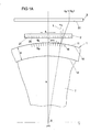
- FIG. 1 a schematically shows a position measuring device for angle measurement with a measuring tape 1 of finite thickness arranged annularly along a circular arc and a scanning unit which comprises a light source (not shown in FIG. 1 a), a scanning plate 2 and a detector 3 in the form of a photodetector.
- the measuring tape 1 and the scanning unit 2, 3 are movable relative to each other, for.
- Example characterized in that the tape measure 1 is set on the outer periphery of an axis S rotatable drum T and the scanning unit 2, 3 stationarily in front of the outer surface (outer annular surface) of the tape measure 1 (and spaced therefrom in the radial direction) ,
- the measuring tape 1 arranged annularly along a circular arc 10 of radius R has an outer annular surface 11 provided with a periodic measuring graduation 15 in the form of a graduated graduation and an inner surface 12 (inner annular surface).
- the periodic measuring graduation 15 may also be provided directly on the outer surface of the drum T rotatable about the axis S. In this case, therefore, the outer surface of the drum forms the annular surface 11 on which the measuring graduation 15 is formed.
- a measuring tape 1 associated scanning 2 of the scanning unit 2, 3 is arranged in front of the outer annular surface 11 of the tape measure and spaced therefrom in such a way that it extends parallel to a tangent t on the outer annular surface 11 of the tape measure 1. Since the tape measure 1 has a certain extent perpendicular to the plane of the ring, that is to say perpendicular to the plane of the drawing of FIG. 1a, this tangent t is not simply a straight line, but rather a tangential plane.
- the scanning 2 is provided on its outer ring surface 11 of the measuring tape 1 facing surface 21 with a scanning graduation 25.
- the outer ring surface 11th facing surface 21 of the scanning 2 and the scanning graduation 25 formed there extend in each case along an axis A parallel to the tangent t on the outer annular surface 11 of the tape measure. 1
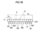
- a detector 3 with a radiation-sensitive surface 31 (detector surface) is arranged, which is a so-called structured photodetector. Its radiation-sensitive surface is formed according to FIG. 1b by a plurality of detector elements arranged one behind the other in the form of photoelements of a width b. The direction along which the detector elements are arranged one behind the other corresponds to the extension axis A of the scanning graduation 25 from FIG. 1a. D.
- the scanning graduation 25 of the scanning 2 and the successively arranged detector elements of the detector 3 extend parallel to each other, namely parallel to the extension axis A, which in turn runs parallel to the tangent t on the outer annular surface 11 of the measuring tape 1 and which the measuring direction corresponds to the scanning unit 2, 3.
- the four detector elements of the detector 3 form a detector group, and the four detector elements of a detector group are each assigned to one of the four phase values 0 °, 90 °, 180 ° and 270 °.
- the period P D of this array of detector elements is four times the width b of a single detector element of phase value 0 °, 90 °, 180 ° or 270 °.
- FIG. 1 b further schematically shows electrical connections 300 of the individual photoelements which form the radiation-sensitive surface 31 of the photodetector 3, wherein photoelements of different detector groups assigned to the same phase value 0 ° or 90 ° or 180 ° or 270 ° are interconnected, so that the output signals of which can be fed jointly to an evaluation unit for evaluation.
- the radiation-sensitive surface 31 of the photodetector 3 Three detector groups consisting of four detector elements (photo elements) of the phase 0 ° or 90 ° or 180 ° or 270 ° are shown in Figure 1 b. This is only a section of the radiation-sensitive surface 31 of the photodetector 3, the typically has ten to fourteen of such each of four photo elements existing and periodically arranged one behind the other detector groups.
- the scanning unit 2, 3 of the position measuring device (angle measuring device) shown in Figures 1 a and 1 b is used for optical scanning of the measuring graduation 15 on the outer annular surface 11 of the ring along a circular arc section 10 arranged tape measure 1.
- the provided with the measuring graduation 15 outer Ring surface 11 of the tape measure 1 irradiated in a known manner with collimated electromagnetic radiation L in the form of light, which was generated by means of a suitable illumination unit (light source) and collimated by means of a suitable condenser lens, as known for example from EP 1 081 457 A2.
- the light L used for scanning the measuring graduation 15 on the outer annular surface 11 of the measuring tape 1 interacts both with the scanning graduation 25 of the transparent scanning 2, which is in a known manner in the beam path of the light L, as well as with the measuring graduation 15 on the outer annular surface eleventh of the measuring tape 1, at which the light is reflected.
- the light beams L modified both by the scanning graduation 25 and by the measuring graduation 15 form on the radiation-sensitive surface 31 of the photodetector 3 a so-called Vernier fringe pattern with a period determined by the grating constant d A of the scanning graduation 25 and the grating constant d M of the measuring graduation 15 is fixed.
- the lattice constant d M also corresponds to the period of the corresponding division.
- the photo elements arranged on the radiation-sensitive surface 31 of the photodetector 3 generate an electrical signal corresponding to this stripe pattern, which is fed to an evaluation unit which determines the extent of a relative movement between the measuring tape 1 and the scanning unit 2, 3 by evaluating the electrical output signals of the photodetector 3.
- the measuring graduation 15 is along a ring-shaped arrangement
- Circular path has the problem that the lattice constant d (x) of the measurement pitch 15 projected along the direction of the collimated light beams L on the facing surface 21 of the scanning plate 2 varies. This will be described in more detail below with reference to a coordinate axis x which runs parallel to the tangent t of the outer annular surface 11 of the measuring tape 1 and parallel to the extension axis A of the scanning graduation 15 of the scanning plate 2.
- the problem associated with the annular arrangement of the measuring graduation 15 can also be represented by the reflection of the collimated light beams L after striking the outer annular surface 11 of the measuring tape 1:
- the light beams L of a collimated radiation beam interact with the scanning graduation 2, whereby an interference fringe pattern is generated in the curved plane of the annular measuring graduation 15.
- This radiation which is characterized by an interference fringe or intensity pattern, scans the measuring graduation 15, which is designed as an amplitude grating with equidistant lines (ie, location-independent grating constant d M ).
- the scanning graduation 25 forms a Vernier strip pattern which is detected by the detector elements of the detector 3 and evaluated in an associated evaluation unit.
- a light beam L which penetrates the scanning graduation 2 at a location with the coordinate x 0 and is subsequently reflected at the outer annular surface 11 of the measuring tape 1 provided with the measuring graduation 15, vividly leads to a signal at the radiation-sensitive surface 31 of the detector 3 at a position x 0 + v (x 0 ) which is shifted by a value v (x 0 ) from the position in the case of a linear arrangement of the measuring tape 11.
- the respective location-dependent displacement v (x) can be calculated for each location x from the geometric arrangement of the components of the described measuring device to each other.
- FIG. 1a The qualitative description made above with reference to FIG. 1a is merely intended to provide an illustrative representation of the problem associated with the projection effect discussed above (as a result of the projection of the measuring graduation 15 of the measuring tape 1 on the facing surface 21 of the scanning graduation 2).
- the wave nature of the light interacting with the two pitches 15, 25 must be taken into account in a concrete quantitative approach. This will happen below.
- a scanning graduation 25 with a location-dependent Scanning pitch d A wherein the local, location-dependent lattice constant d A (x) of the scanning 25 is calculated so that the interaction of the measuring graduation 15 with the scanning 25 in the plane of the radiation-sensitive surface 31 of the detector 3 to a stripe or intensity pattern with a constant period leads. That is, along the extension axis A of the scanning pitch 25, a change in phase of the stripe pattern (Vernier phase) by 2 ⁇ (Vernier period) corresponds to one and the same distance along the extension axis A and the x-axis of the in Figure 1a introduced coordinate system.
- d M denotes the location-independent lattice constant (constant graduation period) of the measuring graduation 15 directly on the measuring tape and R indicates the radius of the annular measuring tape arrangement, ie the distance between the outer ring surface 11 of the measuring tape 1 and the axis of rotation S of the drum and the measuring tape 1 arranged thereon , and D stands for the thickness of the measuring tape 1.
- the present mathematical derivation is based on a quadratic approximation, is quite sufficient in many cases In other cases must be calculated exactly, ie with the dependence of the projected lattice constants of the local inclination angle of the surface 21 according to a cosine function.
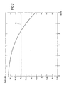
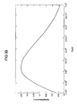
- FIG. 2 shows the location-dependent lattice constant d A (x) of a scanning pitch in the form of a MAP lattice as a function of the distance x from the reference point of the scanning pitch, ie the point at which the scanning pitch has the smallest distance from the measuring graduation.
- the measuring graduation is applied, according to the illustrated example, on a measuring tape which is placed around a drum with a drum diameter of 40 mm, and has a lattice period of 40 ⁇ m.
- the Vernier wavelength A is presently 800 microns.
- the grating constant d A (x) of the MAP grating assumes its maximum value in the form of a scanning grating at the reference point and then becomes smaller with increasing distance from the reference point.
- the lattice constant of the scanning would be between the maximum and the minimum value, as schematically indicated in Figure 2 by the dashed line d c .
- the change of the lattice constant d A (x) along the extension axis A of the scan pitch is significantly less than 1% (even less than 0.5%) and thus represents only a small correction to the basically periodic structure of the scan pitch, so that the small (continuous) variation of the lattice constant d A (x) in the vicinity of each point x at least one local period of the sample division can be defined.
- the decay of the lattice constant from the reference point (zero point) shown in FIG. 2 applies to both directions along the extension axis A of the scanning graduation in the same way, ie both along the positive direction + x and along the opposite direction -x.
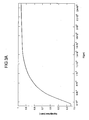
- FIG. 3a shows the normalized magnitude of the signals generated at the detector as a function of the drum radius R in the case of an equidistant scanning pitch, which results from the use of a planar measuring graduation. H. without the inventively provided correction (location dependence) of the lattice constant. It becomes clear that with drum radii of less than 100 mm the signal losses are considerable.
- the signal size has a maximum at exactly this drum radius R and is more than 85% of the maximum possible signal size.
Landscapes
- Physics & Mathematics (AREA)
- General Physics & Mathematics (AREA)
- Optical Transform (AREA)
- Vehicle Body Suspensions (AREA)
- Body Structure For Vehicles (AREA)
- Analysing Materials By The Use Of Radiation (AREA)
- Length Measuring Devices By Optical Means (AREA)
- Transmission And Conversion Of Sensor Element Output (AREA)
Abstract
Description
- Die Erfindung betrifft eine Positionsmesseinrichtung nach dem Oberbegriff des Patentanspruchs 1.
- Eine derartige Positionsmesseinrichtung zur Bestimmung der Relativlage zweier (durch eine Drehbewegung) entlang einer Messrichtung zueinander beweglicher Objekte (Winkelmesseinrichtung) umfasst eine auf einer ringartigen Maßverkörperung, z. B in Form eines Maßbandes, ausgebildete periodische Messteilung; eine Abtasteinheit zum optischen Abtasten der Messteilung mittels elektromagnetischer Strahlung (insbesondere mittels Licht), die in einer Beleuchtungseinrichtung (Lichtquelle) der Abtasteinheit erzeugt wird, wobei die Maßverkörperung und die Abtasteinheit entlang der Messrichtung relativ zueinander bewegbar sind; eine Abtastplatte der Abtasteinheit mit einer entlang einer Achse erstreckten, durch ein Abtastgitter gebildeten Abtastteilung, die im Strahlengang der zum Abtasten der Messteilung verwendeten elektromagnetischen Strahlung angeordnet ist, so dass diese elektromagnetische Strahlung sowohl mit der Abtastteilung als auch mit der Messteilung wechselwirkt; sowie einen Detektor der Abtasteinheit, dessen Detektorfläche zur Detektion einer nach Wechselwirkung mit der Abtastteilung und der Messteilung als Streifenmuster vorliegenden Intensitätsverteilung der elektromagnetischen Strahlung dient, um aus der Änderung der ortsabhängigen Phase der Intensitätsverteilung eine Relativbewegung der Messteilung bezüglich der Abtasteinrichtung erfassen zu können.
- Indem eines der beiden Objekte, deren Relativbewegung mittels der Positionsmesseinrichtung bestimmt werden soll, mit der Messteilung und das andere Objekt mit der Abtasteinrichtung versehen wird, lässt sich aus der Erfassung der Relativbewegung der Abtasteinrichtung bezüglich der Messteilung unmittelbar auf die Relativbewegung der beiden Objekte zueinander schließen.
- Das Messprinzip, das der vorgenannten Positionsmesseinrichtung zugrunde liegt, ist beispielsweise aus der EP 1 081 457 A2, der EP 1 082 309 A1 und der EP 0 754 933 B1 bekannt. So ist in der EP 1 028 309 A1 eine optische Positionsmesseinrichtung zur Bestimmung der Relativlage zweier entlang einer Messrichtung zueinander beweglicher Objekte beschrieben. Diese umfasst mindestens eine mit einem der beiden Objekte verbundene periodische Messteilung sowie eine mit dem anderen Objekt verbundene und somit relativ zu der Messteilung entlang der Messrichtung bewegbare Abtasteinheit. Die Abtasteinheit weist eine Lichtquelle, mindestens eine Abtastteilung sowie eine Detektoranordnung in einer Detektorebene auf, die aus mehreren strahlungsempfindlichen, in Messrichtung hintereinander angeordneten Detektorelementen besteht.
- Wird bei einer Positionsmesseinrichtung der eingangs genannten Art ein als Träger der Messteilung dienendes Maßband ringartig angeordnet, insbesondere durch Aufbringen des Maßbandes auf einen zylindrischen Körper in Form einer Trommel, so kann die Positionsmesseinrichtung zur Winkelmessung verwendet werden. Alternativ kann die entsprechende Messteilung hierzu auch unmittelbar auf der Trommel selbst aufgebracht sein, so dass dann die mit der Messteilung versehene Trommeloberfläche unmittelbar die ringartig umlaufende Maßverkörperung bildet.
- Im Folgenden soll bei der Verwendung des Begriffes "Maßband", sofern nicht ausdrücklich auf ein Maßband endlicher Dicke abgestellt wird, jeweils auch der Grenzfall umfasst sein, dass die Dicke des Maßbandes gegen Null geht: Dieser Grenzfall entspricht einer Situation, in der die Messteilung unmittelbar auf dem (zylindrischen) Körper (in Form einer Trommel) aufgebracht ist, der ansonsten zur Aufnahme des Maßbandes dient.
- Bei einer solchen Anordnung besteht das Problem, dass die auf die Ebene der Abtastplatte projizierte lokale Teilungsperiode der auf der ringartig umlaufenden Maßverkörperung vorgesehenen periodischen Messteilung mit wachsendem Abstand vom Trommelscheitel nach außen hin abnimmt. Daraus ergibt sich eine nach außen hin anwachsende gegenseitige Verschiebung der Teilungsstriche der Abtastteilung einerseits und der Messteilung andererseits bezüglich deren Optimallage, die bei einer linearen periodischen Anordnung sowohl der Messteilung als auch der Abtastteilung vorläge. Die beschriebenen Abweichungen, die aus der ringartigen Anordnung der periodischen Messteilung folgen, führen zu einer Verschlechterung des Modulationsgrades der am Detektor erzeugten Abtastsignale.
- Der Erfindung liegt das Problem zugrunde, eine Positionsmesseinrichtung der eingangs genannten Art zu schaffen, die bei einfachem Aufbau die Kombination einer ringförmigen Maßverkörperung und einer Abtastplatte sowie eines zugehörigen Detektors mit einer zweidimensionalen strahlungsempfindlichen Oberfläche bei guter Qualität der auszuwertenden Abtastsignale gestattet.
- Dieses Problem wird erfindungsgemäß durch eine Positionsmesseinrichtung mit den Merkmalen des Patentanspruchs 1 gelöst.
- Danach variiert die Gitterkonstante der Abtastteilung, also die lokale Periode der Abtastteilung, entlang der Erstreckungsrichtung der Abtastteilung derart, dass die Wegstrecken, auf denen die Phase der an der Detektorfläche vorliegenden Intensitätsverteilung, also des durch Interferenz erzeugten Streifenmusters (entlang der Messrichtung, entlang der die Detektorelemente des Detektors hintereinander angeordnet sind, und somit insbesondere auch parallel zur Erstreckungsachse der Abtastteilung) eine (lineare) Änderung um 2π durchläuft, konstant sind.
- Mit anderen Worten ausgedrückt, nimmt die Phase (Vernierphase) in der durch die Detektionsfläche des Detektors definierten Detektionsebene - unabhängig davon, an welcher Stelle der Ebene die Änderung der Phase betrachtet wird - stets innerhalb einer vorgegebenen Länge bzw. Wegstrecke entlang (insbesondere der so genannten Vernierperiode) linear um 2π zu.
- Die erfindungsgemäß vorgesehene Ausgestaltung der Abtastteilung hat den wesentlichen Vorteil, dass der Modulationsgrad und damit die Signalgrößen des Abtastsignals optimal eingestellt werden, da für beliebige Durchmesser der ringartig angeordneten Maßverkörperung die lokale Teilungsperiode (Gitterkonstante) der Abtastteilung entlang der Messrichtung, d. h. entlang der Erstreckungsachse der Abtastteilung, so bestimmt wird, dass die in der Ebene der Detektoroberfläche erzeugte Periode Intensitätsverteilung der elektromagnetischen Strahlung bzw. des Streifenmusters (Vernierperiode) hinsichtlich der Ausdehnung entlang der Messrichtung stets den gleichen, konstanten Wert aufweist. Hierdurch ist es möglich, für beliebige Durchmesser der ringartig umlaufenden Maßverkörperung, d. h. insbesondere für beliebige Durchmesser einer Trommel, auf der ein mit der Maßverkörperung versehenes Maßband aufgebracht ist, stets den gleichen strukturierten Detektor zur Detektion der elektromagnetischen Strahlung nach Wechselwirkung mit der Messteilung und der Abtastteilung zu verwenden.
- Ein weiterer wichtiger Vorteil der erfindungsgemäßen Ausgestaltung der Abtastteilung besteht in der erhöhten Messgenauigkeit im Fall einer Verschmutzung der Messteilung, da in den Abtastsignalen als Folge der Verschmutzung keine Phasenverschiebungen sondern lediglich unterschiedliche Amplituden auftreten.
- Die vorstehend am Beispiel solcher Positionsmesseinrichtungen erläuterte Erfindung, mit denen an der Detektorfläche ein periodisches, so genanntes Vernier-Streifenmuster erzeugt wird, lässt sich insbesondere auch in dem Fall anwenden, in dem die Periode des Streifenmusters gegen unendlich strebt. In diesem Fall wird eine einheitliche Hell-/Dunkel-Modulation mit konstanter Phase auf einem Abtastfeld erzeugt.
- Bei linearen Positionsmesseinrichtungen, bei denen die Messteilung und die Abtastteilung parallel zueinander entlang einer Messrichtung verlaufen, entspricht ersteres einer Anordnung, bei der die Abtastteilung und die Messteilung eine unterschiedliche Teilungsperiode aufweisen, während der Grenzfall einer einheitlichen Hell-/Dunkel-Modulation konstanter Phase im linearen Fall einer identischen Teilungsperiode der Messteilung einerseits und der Abtastteilung andererseits entspricht.
- Die erfindungsgemäß vorgesehene Variation der Gitterkonstante bzw. der lokalen Periode der Abtastteilung kann konstruktiv insbesondere dadurch realisiert werden, dass die Gitterkonstante der Abtastteilung von einem Referenzpunkt ausgehend in mindestens einer Raumrichtung entlang der Erstreckungsachse der Abtastteilung definiert variiert, insbesondere (kontinuierlich) abnimmt. Hierdurch wird der eingangs beschriebenen Abnahme der auf die Abtastplatte projizierten Messteilung entlang der Erstreckungsachse der Abtastteilung Rechnung getragen.
- Die Anordnung ist dabei bevorzugt derart, dass die Gitterkonstante der Abtastteilung ausgehend von dem besagten Referenzpunkt in zwei zueinander entgegengesetzten, jeweils entlang der Erstreckungsachse der Abtastteilung (entgegengesetzt zueinander) verlaufenden Richtungen abnimmt, und zwar bevorzugt symmetrisch, d. h. die Abnahme ist - von dem Referenzpunkt ausgehend - entlang der beiden zueinander entgegengesetzten Raumrichtungen identisch.
- Die ortsabhängige Gitterkonstante der Abtastteilung kann dabei aus einer ortsabhängigen Gitterphase der Abtastteilung bestimmt werden, die sich aus der auf die Abtastplatte projizierten, ortsabhängigen Gitterphase der Messteilung und einer vorgebbaren, periodischen Phase der an der Detektorfläche der Abtasteinheit vorliegenden Intensitätsverteilung ergibt.
- Aus der ortsabhängigen Gitterphase der Abtastteilung lässt sich dann die ortsaufgelöste Frequenzverteilung der Abtastteilung berechnen, und zwar durch Ableitung der ortsabhängigen Gitterphase nach dem Ort sowie Division durch 2π. Die ortsabhängige Frequenzverteilung bildet das Inverse der lokalen Gitterkonstante bzw. lokalen Teilungsperiode der Abtastteilung, so dass sich diese aus der Frequenzverteilung unmittelbar durch Bildung des Inversen berechnen lässt.
- Die Detektorfläche des Detektors der Abtasteinheit wird bevorzugt durch eine periodische Anordnung von Detektorbereichen (entlang der Erstreckungsachse der Abtastteilung) gebildet, deren Periode auf die Periode desjenigen Streifenmusters abgestimmt ist, für deren Abtastung der entsprechende Detektor zur Erzielung einer maximalen Intensität der elektromagnetischen Strahlung an der strahlungsempfindlichen Oberfläche ausgebildet und vorgesehen ist. Im Falle eines periodisch strukturierten Detektors bedeutet dies insbesondere, dass die strahlungsempfindliche Oberfläche des Detektors eine Periode aufweist, die bis auf ein ganzzahliges Vielfaches mit der Periode des Streifenmusters übereinstimmt.
- Unter der Periode des Detektors wird dabei nicht zwingend die Periode der geometrischen Anordnung der einzelnen Detektorbereiche bzw. Detektorelemente verstanden. Vielmehr ist hierbei auch eine elektrische Verschaltung der einzelnen Detektorbereiche bzw. Detektorelemente zu berücksichtigen. So ist bei einem strukturierten Detektor üblicherweise vorgesehen, dass auf einer Länge, die der Periode des an der strahlungsempfindlichen Oberfläche des Detektors empfangenen Streifenmusters entspricht, vier Detektorelemente angeordnet sind, von denen jedes einem bestimmten Phasenwert, insbesondere einer der Phasen 0°, 90°, 180° oder 270° zugeordnet ist. Hierbei werden dann mehrere Gruppen von jeweils vier Detektoren (entlang der Erstreckungsachse der Abtastteilung) hintereinander angeordnet, wobei aus den einzelnen Detektorgruppen jeweils die Detektorbereiche bzw. Detektorelemente miteinander verschaltet werden, die der gleichen Phase zugeordnet sind. Die Periode eines solchen strukturierten Detektors wird dann definiert durch die Breite jeweils einer Detektorgruppe, die mehrere Detektorbereiche, insbesondere vier Detektorbereiche, umfasst.
- Bei Verwendung eines Detektors mit einer zweidimensionalen, ebenen strahlungsempfindlichen Oberfläche zur Abtastung der Messteilung auf der ringartigen Maßverkörperung erstreckt sich der Detektor in einem definierten (radialen) Abstand von der mit der Messteilung versehenen Oberfläche der Maßverkörperung in tangentialer Richtung (d. h., parallel zu einer Tangente am äußeren Umfang der ringartig ausgebildeten Maßverkörperung). Bei dem strukturierten Detektor sind dementsprechend die einzelnen Detektorbereiche bzw. Detektorelemente entlang einer Richtung parallel zu einer Tangentialen der ringförmigen Maßverkörperung hintereinander angeordnet.
- In entsprechender Weise ist auch die Abtastplatte der Abtasteinheit parallel zu einer die Messrichtung repräsentierenden Tangente am äußeren Umfang der Maßverkörperung angeordnet, und zwar bevorzugt derart, dass die Abtastteilung der Abtastplatte sich parallel zu der Detektorfläche des Detektors erstreckt. Zwar kann der Detektor relativ zur Abtastplatte um eine in Messrichtung verlaufende Achse verkippt sein; jedoch erstrecken sich auch dann die Abtastteilung und die Anordnung der Detektorelemente beide in Messrichtung.
- Diejenige Stelle der Abtastteilung, die den geringsten Abstand von der Messteilung aufweist, die also dem der Abtastteilung zugewandten Scheitelpunkt der Messteilung unmittelbar gegenüber liegt, bildet dabei den Referenzpunkt, von dem ausgehend die Gitterkonstante der Abtastteilung in zwei zueinander entgegengesetzten Richtungen parallel zur Erstreckungsachse der Abtastteilung (symmetrisch) variiert wird.
- Zu beachten ist, dass sich die Erfindung nicht nur auf den Fall anwenden lässt, in dem die Messteilung auf einer äußeren Oberfläche (äußeren Ringfläche) eines Maßbandes vorgesehen ist, sondern auch in dem Fall, in dem die Messteilung auf der inneren Oberfläche (inneren Ringfläche) des Maßbandes ausgebildet ist.
- Sowohl die Abtastteilung als auch die Messteilung können durch so genannte Amplitudengitter gebildet werden, die mit elektromagnetischer Strahlung (insbesondere Licht) derart wechselwirken, dass - entsprechend der Periode des jeweiligen Gitters - eine periodische Abfolge hellerer und dunklerer Lichtbereiche erzeugt wird. Wird die Positionsmesseinrichtung im so genannten Reflektionsverfahren betrieben, so sind in dem entsprechenden Gitter jeweils Markierungen (z.B. Striche) von größerer und kleinerer Reflektivität im Hinblick auf die zum Abtasten verwendete elektromagnetische Strahlung (Licht) vorgesehen. Bei Anwendung des so genannten Durchlichtverfahrens unterscheiden sich die periodisch hintereinander angeordneten Markierungen (Striche) demgegenüber in der Durchlässigkeit für die zum Abtasten verwendete elektromagnetische Strahlung (Licht).
- Die Abtastteilung kann zudem insbesondere als so genanntes MAP-Gitter ("Mixed Amplitude Phase"-Gitter) ausgebildet sein, wie zum Beispiel aus den Figuren 2a und 2b der EP 1 081 457 A2 bekannt. Die in diesem Fall vorzunehmende Berechnung der Gitterphase des Amplitudengitters wird weiter unten anhand eines Ausführungsbeispieles beschrieben werden. Alternativ kann die Abtastteilung auch durch ein Phasengitter gebildet werden. Ob ein Amplitudengitter, ein Phasengitter oder ein gemischtes Amplituden-/Phasengitter (MAP-Gitter) zum Einsatz kommt, hängt vom jeweiligen Design des Messsystems ab. Dabei spielen etwa die tolerierbaren Signalgrößen, die Toleranz bezüglich des Abtastabstandes und Kosten eine Rolle.
- Zur Abtastung des Maßbandes wird im Rahmen der vorliegenden Erfindung bevorzugt kollimierte (parallelisierte) elektromagnetische Strahlung in Form von Licht verwendet.
- Weitere Merkmale und Vorteile der Erfindung werden bei der nachfolgenden Beschreibung eines Ausführungsbeispieles anhand der Figuren deutlich werden.
- Es zeigen:
- Fig. 1 a
- eine schematische Darstellung eines Ausschnittes eines ringförmig angeordneten Maßbandes mit einer periodischen Messteilung sowie einer zugeordneten Abtasteinheit mit einer Abtastplatte und einem Detektor;
- Fig. 1 b
- die strahlungsempfindliche Oberfläche des strukturierten Detektors der Abtasteinheit gemäß Figur 1 a;
- Fig. 2
- eine grafische Darstellung der Ortsabhängigkeit der Gitterkonstante der auf der Abtastplatte vorgesehenen Abtastteilung;
- Fig. 3a
- die auf ein ebenes Maßband normierte Signalgröße des Abtastsignales des strukturierten Detektors in Abhängigkeit vom Radius des ringförmig angeordneten Maßbandes bei Verwendung einer äquidistanten Abtastteilung;
- Fig. 3b
- die Signalgröße des Abtastsignales des strukturierten Detektors in Abhängigkeit vom Radius des ringförmig angeordneten Maßbandes bei Verwendung einer Abtastteilung mit einer ortsabhängigen Gitterkonstante.
- Figur 1 a zeigt schematisch eine Positionsmesseinrichtung zur Winkelmessung mit einem ringförmig entlang eines Kreisbogens angeordneten Maßbands 1 endlicher Dicke und eine Abtasteinheit, die eine in Figur 1 a nicht dargestellte Lichtquelle, eine Abtastplatte 2 und einen Detektor 3 in Form eines Fotodetektors umfasst.
- Das Maßband 1 und die Abtasteinheit 2, 3 sind relativ zueinander beweglich, z. B. dadurch, dass das Maßband 1 am äußeren Umfang einer um eine Achse S drehbaren Trommel T festgelegt ist und die Abtasteinheit 2, 3 stationär vor der äußeren Oberfläche (äußeren Ringfläche) des Maßbandes 1 (und von dieser in radialer Richtung beabstandet) angeordnet ist.
- Das ringförmig entlang eines Kreisbogens 10 mit dem Radius R angeordnete Maßband 1 weist eine mit einer periodischen Messteilung 15 in Form einer Strichteilung versehene äußere Ringfläche 11 sowie eine innere Oberfläche 12 (innere Ringfläche) auf. Alternativ kann die periodische Messteilung 15 auch unmittelbar auf der äußeren Oberfläche der um die Achse S drehbaren Trommel T vorgesehen sein. In diesem Fall bildet also die äußere Oberfläche der Trommel die Ringfläche 11, auf der die Messteilung 15 ausgebildet ist.
- Eine dem Maßband 1 zugeordnete Abtastplatte 2 der Abtasteinheit 2, 3 ist vor der äußeren Ringfläche 11 des Maßbandes und von dieser beabstandet angeordnet und zwar in der Weise, dass sie sich parallel zu einer Tangente t an der äußeren Ringfläche 11 des Maßbandes 1 erstreckt. Da das Maßband 1 eine gewisse Ausdehnung senkrecht zur Ringebene, also senkrecht zu der Zeichenebene der Figur 1 a, aufweist, handelt es sich bei dieser Tangente t nicht einfach um eine Gerade, sondern vielmehr um eine Tangentialebene.
- Die Abtastplatte 2 ist an ihrer der äußeren Ringfläche 11 des Maßbandes 1 zugewandten Oberfläche 21 mit einer Abtastteilung 25 versehen. Die der äußeren Ringfläche 11 zugewandte Oberfläche 21 der Abtastplatte 2 sowie die dort ausgebildete Abtastteilung 25 erstrecken sich dabei jeweils entlang einer Achse A parallel zu der Tangente t an der äußeren Ringfläche 11 des Maßbandes 1.
- Von dem Maßband 1 her gesehen ist hinter der Abtastplatte 2 ein Detektor 3 mit einer strahlungsempfindlichen Oberfläche 31 (Detektorfläche) angeordnet, bei dem es sich um einen sogenannten strukturierten Fotodetektor handelt. Dessen strahlungsempfindliche Oberfläche wird gemäß Figur 1b gebildet durch eine Mehrzahl hintereinander angeordneter Detektorelemente in Form von Fotoelementen einer Breite b. Die Richtung, entlang der die Detektorelemente hintereinander angeordnet sind, entspricht dabei der Erstreckungsachse A der Abtastteilung 25 aus Figur 1a. D. h., die Abtastteilung 25 der Abtastplatte 2 sowie die hintereinander angeordneten Detektorelemente des Detektors 3 erstrecken sich parallel zueinander, nämlich parallel zur Erstreckungsachse A, welche wiederum parallel zu der Tangente t an der äußeren Ringfläche 11 des Maßbandes 1 verläuft und welche der Messrichtung an der Abtasteinheit 2, 3 entspricht.
- Dabei bilden jeweils vier Detektorelemente des Detektors 3 eine Detektorgruppe, und es sind die vier Detektorelemente einer Detektorgruppe jeweils einem der vier Phasenwerte 0°, 90°, 180° und 270° zugeordnet. Somit entspricht die Periode PD dieser Anordnung von Detektorelementen dem Vierfachen der Breite b eines einzelnen Detektorelementes des Phasenwertes 0°, 90°, 180° oder 270°.
- In Figur 1b sind ferner schematisch elektrische Anschlüsse 300 der einzelnen Fotoelemente dargestellt, die die strahlungsempfindliche Oberfläche 31 des Fotodetektors 3 bilden, wobei jeweils dem selben Phasenwert 0° oder 90° oder 180° oder 270° zugeordnete Fotoelemente unterschiedlicher Detektorgruppen miteinander verschaltet sind, so dass deren Ausgangssignale zur Auswertung gemeinsam einer Auswerteeinheit zugeführt werden können.
- Von der strahlungsempfindlichen Oberfläche 31 des Fotodetektors 3 sind in Figur 1 b drei Detektorgruppen bestehend aus jeweils vier Detektorelementen (Fotoelementen) der Phase 0° bzw. 90° bzw. 180° bzw. 270° dargestellt. Hierbei handelt es sich nur um einen Ausschnitt der strahlungsempfindlichen Oberfläche 31 des Fotodetektors 3, die typischerweise zehn bis vierzehn derartige aus jeweils vier Fotoelementen bestehender und periodisch hintereinander angeordneter Detektorgruppen aufweist.
- Die Abtasteinheit 2, 3 der in den Figuren 1 a und 1 b dargestellten Positionsmesseinrichtung (Winkelmesseinrichtung) dient zur optischen Abtastung der Messteilung 15 auf der äußeren Ringfläche 11 des ringförmig entlang eines Kreisbogenabschnittes 10 angeordneten Maßbandes 1. Hierzu wird die mit der Messteilung 15 versehene äußere Ringfläche 11 des Maßbandes 1 in bekannter Weise mit kollimierter elektromagnetischer Strahlung L in Form von Licht bestrahlt, welches mittels einer geeigneten Beleuchtungseinheit (Lichtquelle) erzeugt und mittels einer geeigneten Kondensorlinse kollimiert wurde, wie beispielsweise aus der EP 1 081 457 A2 bekannt. Das zur Abtastung der Messteilung 15 auf der äußeren Ringfläche 11 des Maßbandes 1 verwendete Licht L wechselwirkt sowohl mit der Abtastteilung 25 der lichtdurchlässigen Abtastplatte 2, die in bekannter Weise im Strahlengang des Lichtes L liegt, als auch mit der Messteilung 15 auf der äußeren Ringfläche 11 des Maßbandes 1, an der das Licht reflektiert wird.
- Die sowohl durch die Abtastteilung 25 als auch durch die Messteilung 15 modifizierten Lichtstrahlen L bilden auf der strahlungsempfindlichen Oberfläche 31 des Fotodetektors 3 ein sogenanntes Vernier-Streifenmuster mit einer Periode, die durch die Gitterkonstante dA der Abtastteilung 25 sowie die Gitterkonstante dM der Messteilung 15 festgelegt ist. Im Fall einer ortsunabhängigen Gitterkonstante, wie sie vorliegend insbesondere im Fall der Messteilung 15 des Maßbandes 11 vorliegt, entspricht die Gitterkonstante dM zugleich der Periode der entsprechenden Teilung.
- Die auf der strahlungsempfindlichen Oberfläche 31 des Fotodetektors 3 angeordneten Fotoelemente erzeugen ein diesem Streifenmuster entsprechendes elektrisches Signal, welches einer Auswerteeinheit zugeführt wird, die durch Auswertung der elektrischen Ausgangssignale des Fotodetektors 3 das Ausmaß einer Relativbewegung zwischen Maßband 1 und Abtasteinheit 2, 3 ermittelt.
- Im Vergleich zu einer auf einem linearen Maßstab vorgesehenen Messteilung besteht vorliegend aufgrund der ringförmigen Anordnung der Messteilung 15 entlang einer Kreisbahn das Problem, dass die Gitterkonstante d(x) der entlang der Richtung der kollimierten Lichtstrahlen L auf die zugewandte Oberfläche 21 der Abtastplatte 2 projizierten Messteilung 15 variiert. Dies soll nachfolgend näher beschrieben werden anhand einer Koordinatenachse x, die parallel zu der Tangente t der äußeren Ringfläche 11 des Maßbandes 1 sowie parallel zu der Erstreckungsachse A der Abtastteilung 15 der Abtastplatte 2 verläuft.
- Mit x = 0 wird dabei derjenige Punkt bezeichnet, an dem die äußere Ringfläche 11 des Maßbandes 1 und somit die Messteilung 15 den geringsten Abstand (in radialer Richtung R) von der zugewandten Oberfläche 21 der Abtastplatte 2 und damit der Abtastteilung 25 haben. Der Punkt mit der Koordinate x = 0 wird nachfolgend auf dem Maßband 1 als Scheitelpunkt bezeichnet und auf der Abtastplatte 2 als Referenzpunkt.
- Anhand Figur 1 a wird dann deutlich, dass bei einer Projektion der Messteilung 15 auf die zugewandte Oberfläche 21 der Abtastteilung 2 die Gitterkonstante d(x) der auf die besagte Oberfläche 21 projizierten Messteilung 15 vom Referenzpunkt (x = 0) der Abtastplatte 2 ausgehend in zueinander entgegengesetzten Richtungen x, -x (parallel zur Erstreckungsachse A der Abtastteilung 25) nach außen hin (weg von dem Referenzpunkt) immer kleiner wird. Die Gitterkonstante d(x) der auf die zugewandte Oberfläche 21 der Abtastplatte 2 projizierten Messteilung 15 fällt somit vom Referenzpunkt (x = 0) der Abtastplatte 2 ausgehend nach außen hin, also entlang der entgegengesetzten Richtungen x, -x, jeweils kontinuierlich ab.
- Die mit der ringförmigen Anordnung der Messteilung 15 verbundene Problematik kann auch anhand der Reflektion der kollimierten Lichtstrahlen L nach dem Auftreffen auf die äußere Ringfläche 11 des Maßbandes 1 dargestellt werden:
- Wie weiter oben bereits erläutert, wechselwirken die Lichtstrahlen L eines kollimierten Strahlungsbündels mit der Abtastteilung 2, wodurch ein Interferenzstreifenmuster in der gekrümmten Ebene der ringförmig angeordneten Messteilung 15 erzeugt wird. Diese durch ein Interferenzstreifen- bzw. Intensitätsmuster charakterisierte Strahlung tastet die Messteilung 15, die als Amplitudengitter mit äquidistanten Strichen (also ortsunabhängiger Gitterkonstante dM) ausgebildet ist, ab. Durch das Zusammenwirken der Abtastteilung 25 mit der Trommelteilung 15 entsteht in der durch die strahlungsempfindliche Oberfläche 31 (Detektionsfläche) des Detektors 3 definierten Detektionsebene ein Vernier-Streifenmuster, das durch die als Fotoelemente ausgebildeten Detektorelemente des Detektors 3 erfasst und in einer zugeordneten Auswerteeinheit ausgewertet wird. Dabei führt ein Lichtstrahl L, der an einer Stelle mit der Koordinate x0 die Abtastteilung 2 durchdringt und anschließend an der mit der Messteilung 15 versehenen äußeren Ringfläche 11 des Maßbandes 1 reflektiert wird, anschaulich gesprochen zu einem Signal an der strahlungsempfindlichen Oberfläche 31 des Detektors 3 an einer Stelle x0 + v(x0), die um einen Wert v(x0) gegenüber der Position im Fall einer linearen Anordnung des Maßbandes 11 verschoben ist. Die jeweilige ortsabhängige Verschiebung v(x) lässt sich für jede Stelle x aus der geometrischen Anordnung der Komponenten der beschriebenen Messeinrichtung zueinander berechnen.
- Die vorstehend anhand Figur 1a ausgeführte qualitative Darlegung soll dabei lediglich eine anschauliche Darstellung des Problems liefern, das mit dem weiter oben besprochenen Projektionseffekt (als Folge der Projektion der Messteilung 15 des Maßbandes 1 auf die zugewandte Oberfläche 21 der Abtastteilung 2) verbunden ist. Tatsächlich muss natürlich bei einer konkreten quantitativen Betrachtungsweise die Wellennatur des mit den beiden Teilungen 15, 25 wechselwirkenden Lichtes berücksichtigt werden. Dies wird nachfolgend geschehen.
- Folge des vorstehend beschriebenen Projektionseffektes ist in jedem Fall, dass bei einer äquidistanten Anordnung sowohl der Teilungsstriche der Messteilung 15 als auch der Teilungsstriche der Abtastteilung 25 kein Streifenmuster (Intensitätsmuster) konstanter Periode an der strahlungsempfindlichen Oberfläche 31 des Detektors 3 erzeugt wird. Dies führt zu Einbußen hinsichtlich der Signalgröße der vom Detektor 3 erzeugten und einer Auswerteeinheit zuzuführenden Abtastsignale, wenn die strahlungsempfindliche Oberfläche 31 des Detektors 3 in üblicher Weise durch eine periodische Anordnung von Fotoelementen gleicher Breite b (vergleiche Figur 1 b) gebildet wird.
- Zur Beseitigung dieses Nachteils ist vorliegend auf der der Messteilung 15 zugewandten Oberfläche 21 der Abtastplatte 2 eine Abtastteilung 25 mit einer ortsabhängigen Abtastteilung dA vorgesehen, wobei die lokale, ortsabhängige Gitterkonstante dA(x) der Abtastteilung 25 so berechnet wird, dass das Zusammenwirken der Messteilung 15 mit der Abtastteilung 25 in der Ebene der strahlungsempfindlichen Oberfläche 31 des Detektors 3 zu einem Streifen- bzw. Intensitätsmuster mit konstanter Periode führt. D. h., entlang der Erstreckungsachse A der Abtastteilung 25 betrachtet, entspricht eine Änderung der Phase des Streifenmusters (Vernier-Phase) um 2π (Vernier-Periode) jeweils ein und derselben Wegstrecke entlang der Erstreckungsachse A bzw. der x-Achse des in Figur 1a eingeführten Koordinatensystems.
- Wenn nachfolgend von der ortsabhängigen Gitterkonstanten dA(x) der Abtastteilung gesprochen wird, so bezieht sich diese Gitterkonstante zunächst beispielhaft auf ein Amplitudengitter oder Phasengitter mit Phasentiefe π/2. Wird ein MAP-Gitter oder ein Phasengitter mit Phasentiefe π eingesetzt, so gilt:

- Die mathematische Formulierung der Berechnung der Ortsabhängigkeit der Gitterkonstanten dA (x) der Abtastteilung 2 geht aus von der Ortsabhängigkeit der auf die zugewandte Oberfläche 21 der Abtastplatte 2 projizierten ortsabhängigen Gitterkonstante d(x) der Messteilung 15:

- Die vorliegende mathematische Herleitung beruht auf einer quadratischen Näherung, die für viele Anwendungen völlig ausreicht In anderen Fällen muss exakt gerechnet werden, d. h. mit der Abhängigkeit der projizierten Gitterkonstanten von dem lokalen Neigungswinkel der Oberfläche 21 gemäß einer Kosinus-Funktion.
- Es ergibt sich für die ortsabhängige Gitterphase der projizierten Messteilung, die als das mit 2.π multiplizierte, integrierte Inverse der ortsabhängigen projizierten Gitterkonstante d(x) der Messteilung 15 berechnet wird:


- Weiterhin sei angenommen, dass für die Vernier-Periode A des auf der strahlungsempfindlichen Oberfläche 31 (Detektorfläche) des Detektors 3 erzeugten Vernier-Streifenmusters ein definierter, vorgebbarer Wert angestrebt wird, der sich aus der in Figur 1b dargestellten Periodizität der Anordnung der Detektorelemente (Fotoelemente) des Detektors 3 ergibt. Unter Vorgabe eines definierten Wertes für A beträgt die ortsabhängige Vernier-Phase an der strahlungsempfindlichen Oberfläche 31 (Detektorfläche) des Detektors 3:

wobei zs den senkrechten Sensorabstand bei x = 0 bezeichnet, also den kürzesten Abstand des Detektors 3 von der Messteilung 15. - Aus der oben angegebenen ortsabhängigen Gitterphase der auf die zugewandte Oberfläche 21 der Abtastteilung 2 projizierten Messteilung 15 sowie aus der ebenfalls vorstehend angegebenen ortsabhängigen Vernier-Phase (unter Berücksichtigung der vorgegebenen Vernierperiode A sowie des vorgegebenen Sensorabstandes zs) des an der strahlungsempfindlichen Oberfläche 31 des Detektors 3 vorliegenden Vernier-Streifenmusters ergibt sich für die Gitterphase der durch eine Amplitudenstruktur gebildeten Abtastteilung:

- Hieraus lässt sich die sogenannte örtliche Frequenzverteilung der Amplitudenstruktur der Abtastteilung berechnen als:

- Das Inverse dieser Frequenzverteilung gA(x) ergibt dann die zu berechnende ortsabhängige Gitterkonstante dA(x) der Abtastteilung.
- Figur 2 zeigt die ortsabhängige Gitterkonstante dA(x) einer Abtastteilung in Form eines MAP-Gitters in Abhängigkeit vom Abstand x vom Referenzpunkt der Abtastteilung, also desjenigen Punktes, an dem die Abtastteilung den geringsten Abstand von der Messteilung aufweist. Die Messteilung ist gemäß dem dargestellten Beispiel auf einem Maßband aufgebracht, welches um eine Trommel mit einem Trommeldurchmesser von 40 mm gelegt ist, und sie weist eine Gitterkonstante bzw. Periode von 40 µm auf. Die Vernier-Wellenlänge A beträgt vorliegend 800 µm.
- Anhand Figur 2 ist erkennbar, dass die Gitterkonstante dA(x) des MAP-Gitters der Abtastteilung in Form eines Abtastgitters am Referenzpunkt ihren maximalen Wert annimmt und dann mit zunehmendem Abstand vom Referenzpunkt kleiner wird. Im linearen Fall, das heißt im Fall einer linear erstreckten Messteilung, anstelle einer ringförmig um eine Trommel gelegten Messteilung, läge die Gitterkonstante der Abtastteilung zwischen dem maximalen und dem minimalen Wert, wie in Figur 2 anhand der gestrichelten Linie dc schematisch angedeutet. Die Änderung der Gitterkonstante dA(x) entlang der Erstreckungsachse A der Abtastteilung beträgt dabei deutlich weniger als 1 % (sogar weniger als 0,5%) und stellt somit nur eine kleine Korrektur an der grundsätzlich periodischen Struktur der Abtastteilung dar, so dass wegen der geringen (kontinuierlichen) Variation der Gitterkonstante dA(x) in der Umgebung jedes Punktes x zumindest eine lokale Periode der Abtastteilung definiert werden kann.
- Der in Figur 2 dargestellte Abfall der Gitterkonstante vom Referenzpunkt (Null-Punkt) gilt für beide Richtungen entlang der Erstreckungsachse A der Abtastteilung in gleicher Weise, also sowohl entlang positiver Richtung +x als auch entlang der entgegengesetzten Richtung -x.
- Ohne die vorstehend quantitativ beschriebene und in Figur 2 grafisch dargestellte Ortsabhängigkeit der Gitterkonstante der Abtastteilung würde die Vernier-Periode an der Detektorfläche des Detektors mit wachsendem Abstand von demjenigen Punkt mit dem geringsten Abstand von der Trommel variieren, mit der Folge einer erheblichen Reduzierung der Größe des am Detektor erzeugten Signals für kleine Trommelradien, wie in Figur 3a dargestellt.
- Figur 3a zeigt die auf 1 als Maximalwert - der sich bei Verwendung einer ebenen Messteilung ergibt - normierte Größe der am Detektor erzeugten Signale in Abhängigkeit vom Trommelradius R bei einer äquidistanten Abtastteilung, d. h. ohne die erfindungsgemäß vorgesehene Korrektur (Ortsabhängigkeit) der Gitterkonstante. Es wird deutlich, dass bei Trommelradien von weniger als 100 mm die Signaleinbußen erheblich sind.
- Abbildung 3b zeigt die Signalgröße in Abhängigkeit vom Trommelradius R im Fall einer Optimierung der Gitterkonstanten des Abtastgitters für einen Trommelradius R = 40 mm. Hier weist die Signalgröße bei genau diesem Trommelradius R ein Maximum auf und liegt bei über 85% der maximal möglichen Signalgröße.
Claims (21)
- Positionsmesseinrichtung mit- einer auf einer ringartig umlaufenden Maßverkörperung vorgesehenen Messteilung,- einer Abtasteinheit zum optischen Abtasten der Messteilung mittels elektromagnetischer Strahlung,- einer Abtastplatte der Abtasteinheit mit einer entlang einer Achse erstreckten, durch ein Abtastgitter gebildeten Abtastteilung, die im Strahlengang der zum Abtasten der Messteilung verwendeten elektromagnetischen Strahlung angeordnet ist, so dass diese sowohl mit der Abtastteilung als auch mit der Messteilung wechselwirkt, und- einem Detektor der Abtasteinheit, dessen Detektorfläche zur Detektion der nach Wechselwirkung mit der Abtastteilung und der Messteilung als Streifenmuster vorliegenden Intensitätsverteilung der elektromagnetischen Strahlung dient, um Bewegungen der Maßverkörperung relativ zu der Abtasteinheit zu erfassen,
dadurch gekennzeichnet,
dass die Gitterkonstante (dA) der Abtastteilung (25) entlang der Erstreckungsrichtung (A) der Abtastteilung (25) derart variiert, dass die Wegstrecken, auf denen die Phase des an der Detektorfläche (31) vorliegenden Streifenmusters eine Änderung um 2π durchläuft, konstant sind. - Positionsmesseinrichtung nach Anspruch 1, dadurch gekennzeichnet, dass die Gitterkonstante (dA) der Abtastteilung (25) von einem Referenzpunkt (0) ausgehend in mindestens einer Raumrichtung (x, -x) entlang der Erstreckungsachse (A) der Abtastteilung (25) gemäß einer definierten Funktion variiert.
- Positionsmesseinrichtung nach Anspruch 1 oder 2, dadurch gekennzeichnet, dass die Gitterkonstante (dA) der Abtastteilung (25) von einem Referenzpunkt (0) ausgehend in mindestens einer Raumrichtung (x, -x) entlang der Erstreckungsachse (A) der Abtastteilung (25) abnimmt.
- Positionsmesseinrichtung mit- einer auf einer ringartig umlaufenden Maßverkörperung vorgesehenen Messteilung,- einer Abtasteinheit zum optischen Abtasten der Messteilung mittels elektromagnetischer Strahlung,- einer Abtastplatte der Abtasteinheit mit einer entlang einer Detektionsachse erstreckten, durch ein Abtastgitter gebildeten Abtastteilung, die im Strahlengang der zum Abtasten der Messteilung verwendeten elektromagnetischen Strahlung angeordnet ist, so dass diese sowohl mit der Abtastteilung als auch mit der Messteilung wechselwirkt, und- einem Detektor der Abtasteinheit, dessen Detektorfläche zur Detektion der nach Wechselwirkung mit der Abtastteilung und der Messteilung vorliegenden elektromagnetischen Strahlung dient, um Bewegungen der Maßverkörperung relativ zu der Abtasteinheit zu erfassen,
dadurch gekennzeichnet, dass die Gitterkonstante (dA) der Abtastteilung (25) von einem Referenzpunkt (0) ausgehend in mindestens einer Raumrichtung (x, -x) entlang der Erstreckungsachse (A) der Abtastteilung (25) abnimmt. - Positionsmesseinrichtung nach Anspruch 4, dadurch gekennzeichnet, dass die Gitterkonstante (dA ) der Abtastteilung (25) entlang der Erstreckungsachse (A) der Abtastteilung (25) derart variiert, dass die Wegstrecken, auf denen die Phase einer an der Detektorfläche (31) in Form eines Streifenmusters vorliegenden Intensitätsverteilung der elektromagnetischen Strahlung eine Änderung um 2π durchläuft, konstant sind.
- Positionsmesseinrichtung nach einem der Ansprüche 2 bis 5, dadurch gekennzeichnet, dass die Gitterkonstante (dA) der Abtasteilung (25) ausgehend von dem Referenzpunkt (0) in zwei zueinander entgegengesetzten, jeweils entlang der Erstreckungsachse (A) der Abtastteilung (25) erstreckten Richtungen (x, -x) abnimmt.
- Positionsmesseinrichtung nach Anspruch 6, dadurch gekennzeichnet, dass die Abnahme entlang der beiden entgegengesetzten Richtungen (x, -x) symmetrisch bezüglich des Referenzpunktes (0) erfolgt.
- Positionsmesseinrichtung nach einem der vorhergehenden Ansprüche, dadurch gekennzeichnet, dass die ortsabhängige Gitterkonstante (dA) der Abtastteilung (25) bestimmt ist durch die Ortsabhängigkeit der Gitterphase der Abtastteilung (25), welche sich aus der auf die Erstreckungsachse (A) der Abtastteilung (25) projizierten ortsabhängigen Gitterphase der Messteilung (15) und einer vorgebbaren ortsabhängigen Phase eines gewünschten Streifenmusters der elektromagnetischen Strahlung an der Detektorfläche (31) ergibt.
- Positionsmesseinrichtung nach Anspruch 8, dadurch gekennzeichnet, dass die ortsabhängige Gitterkonstante (dA (x)) der Abtastteilung (25) als Inverses der Frequenzverteilung

- Positionsmesseinrichtung nach einem der vorhergehenden Ansprüche, dadurch gekennzeichnet, dass die Detektorfläche (31) des Detektors (3) durch eine periodische Anordnung von Detektorbereichen gebildet wird, die entlang einer Detektorachse hintereinander angeordnet sind und deren Periode (PD) auf die Periode desjenigen Streifenmusters abgestimmt ist, für dessen Detektion der Detektor (3) ausgebildet ist.
- Positionsmesseinrichtung nach Anspruch 10, dadurch gekennzeichnet, dass die Detektorbereiche durch Detektorelemente, insbesondere in Form von Fotoelementen, gebildet werden.
- Positionsmesseinrichtung nach Anspruch 10 oder 11, dadurch gekennzeichnet, dass jeweils vier Detektorbereiche (0°, 90°, 180°, 270°) zu einer Detektorgruppe zusammengefasst sind und dass die Detektorgruppen periodisch mit einer definierten Periode (PD) hintereinander angeordnet sind.
- Positionsmesseinrichtung nach Anspruch 12, dadurch gekennzeichnet, dass die einzelnen Detektorbereiche (0°, 90°, 180°, 270°) einer Detektorgruppe jeweils einem Phasenwert zugeordnet sind und dass phasengleiche Detektorbereiche unterschiedlicher Detektorgruppen elektrisch miteinander verschaltet sind.
- Positionsmesseinrichtung nach einem der vorhergehenden Ansprüche, dadurch gekennzeichnet, dass der Detektor (3) eine ebene, im Wesentlichen zweidimensionale Detektorfläche (31) aufweist.
- Positionsmesseinrichtung nach einem der vorhergehenden Ansprüche, dadurch gekennzeichnet, dass die Messteilung (15) und/oder die Abtastteilung (25) durch ein Amplitudengitter gebildet werden.
- Positionsmesseinrichtung nach einem der vorhergehenden Ansprüche, dadurch gekennzeichnet, dass die Abtastteilung (25) durch ein MAP-Gitter gebildet wird.
- Positionsmesseinrichtung nach Anspruch 9 und Anspruch 16, dadurch gekennzeichnet, dass sich die ortsabhängige Phase der Abtastteilung ergibt als Summe der auf die Erstreckungsachse (A) der Abtastteilung (25) projizierten ortsabhängigen Gitterphase der Messteilung (15) und einer vorgebbaren ortsabhängigen Phase eines Streifenmusters der elektromagnetischen Strahlung an der Detektorfläche (31).
- Positionsmesseinrichtung nach einem der Ansprüche 1 bis 14, dadurch gekennzeichnet, dass die Abtastteilung (25) durch ein Phasengitter gebildet wird.
- Positionsmesseinrichtung nach einem der vorhergehenden Ansprüche, dadurch gekennzeichnet, dass die Messteilung (15) der Maßverkörperung (1) mittels elektromagnetischer Strahlung in Form kollimierten Lichtes abgetastet wird.
- Positionsmesseinrichtung nach einem der vorhergehenden Ansprüche, dadurch gekennzeichnet, dass die Messteilung (15) auf einem ringartig auf einer drehbaren Trommel (T) angeordneten Maßband (1) vorgesehen ist.
- Positionsmesseinrichtung nach einem der Ansprüche 1 bis 19, dadurch gekennzeichnet, dass die Messteilung (15) unmittelbar auf einer Oberfläche einer drehbaren Trommel (T) vorgesehen ist.
Applications Claiming Priority (1)
| Application Number | Priority Date | Filing Date | Title |
|---|---|---|---|
| DE102004035172A DE102004035172A1 (de) | 2004-07-16 | 2004-07-16 | Positionsmesseinrichtung |
Publications (3)
| Publication Number | Publication Date |
|---|---|
| EP1617182A2 true EP1617182A2 (de) | 2006-01-18 |
| EP1617182A3 EP1617182A3 (de) | 2006-02-15 |
| EP1617182B1 EP1617182B1 (de) | 2009-10-21 |
Family
ID=35285382
Family Applications (1)
| Application Number | Title | Priority Date | Filing Date |
|---|---|---|---|
| EP05010388A Expired - Lifetime EP1617182B1 (de) | 2004-07-16 | 2005-05-12 | Positionsmesseinrichtung |
Country Status (5)
| Country | Link |
|---|---|
| US (1) | US7297935B2 (de) |
| EP (1) | EP1617182B1 (de) |
| JP (1) | JP4942314B2 (de) |
| AT (1) | ATE446496T1 (de) |
| DE (2) | DE102004035172A1 (de) |
Cited By (1)
| Publication number | Priority date | Publication date | Assignee | Title |
|---|---|---|---|---|
| CN108151634A (zh) * | 2016-12-02 | 2018-06-12 | 约翰内斯·海德汉博士有限公司 | 位置测量机构和用于运行位置测量机构的方法 |
Families Citing this family (9)
| Publication number | Priority date | Publication date | Assignee | Title |
|---|---|---|---|---|
| EP1519158B1 (de) * | 2003-09-23 | 2010-08-11 | Dr. Johannes Heidenhain GmbH | Positionsmesseinrichtung |
| DE102010029211A1 (de) * | 2010-05-21 | 2011-11-24 | Dr. Johannes Heidenhain Gmbh | Optische Positionsmesseinrichtung |
| JP5832088B2 (ja) * | 2010-12-15 | 2015-12-16 | キヤノン株式会社 | ロータリーエンコーダ |
| DE102012222077A1 (de) * | 2012-12-03 | 2014-06-05 | Dr. Johannes Heidenhain Gmbh | Positionsmesseinrichtung |
| JP5974154B2 (ja) * | 2015-10-28 | 2016-08-23 | キヤノン株式会社 | ロータリーエンコーダ |
| CN105372736B (zh) * | 2015-12-25 | 2017-12-08 | 夏立新 | 一种等权定相指标光栅 |
| CN114046708B (zh) * | 2021-12-03 | 2024-05-03 | 上海嘉麟杰纺织科技有限公司 | 一种测量面料格子宽度的装置 |
| CN114046966A (zh) * | 2021-12-09 | 2022-02-15 | 欧普照明股份有限公司 | 用于测量光束角和光通量的测量设备、系统及方法 |
| CN118189818B (zh) * | 2024-05-14 | 2024-07-16 | 深圳市斯普莱特激光科技有限公司 | 一种激光打标的空间平面坐标测定机构 |
Family Cites Families (16)
| Publication number | Priority date | Publication date | Assignee | Title |
|---|---|---|---|---|
| US4912322A (en) * | 1986-08-15 | 1990-03-27 | Mitutoyo Mfg. Co., Ltd. | Optical type displacement detecting device |
| DE3818218A1 (de) * | 1988-04-16 | 1989-10-26 | Heidenhain Gmbh Dr Johannes | Lichtelektrische winkelmesseinrichtung |
| EP0513427B1 (de) * | 1991-05-18 | 1994-07-06 | Dr. Johannes Heidenhain GmbH | Interferentielle Positionsmessvorrichtung |
| US5471054A (en) * | 1991-09-30 | 1995-11-28 | Nf. T&M. Systems, Inc. | Encoder for providing calibrated measurement capability of rotation or linear movement of an object, label medium and an optical identification system |
| JPH05312594A (ja) * | 1992-05-08 | 1993-11-22 | Ricoh Co Ltd | 格子作製方法 |
| DE19511068A1 (de) * | 1995-03-25 | 1996-09-26 | Heidenhain Gmbh Dr Johannes | Lichtelektrische Positionsmeßeinrichtung |
| DE19525874A1 (de) | 1995-07-15 | 1997-01-16 | Heidenhain Gmbh Dr Johannes | Positionsmeßvorrichtung |
| WO2000011431A1 (en) * | 1998-08-21 | 2000-03-02 | Parriaux Olivier M | Device for measuring translation, rotation or velocity via light beam interference |
| EP1028309B1 (de) * | 1999-02-04 | 2003-04-16 | Dr. Johannes Heidenhain GmbH | Optische Positionsmesseinrichtung |
| JP3564000B2 (ja) * | 1999-04-28 | 2004-09-08 | ペンタックス株式会社 | エンコーダ |
| DE19941318A1 (de) * | 1999-08-31 | 2001-03-15 | Heidenhain Gmbh Dr Johannes | Optische Positionsmeßeinrichtung |
| DE19956912A1 (de) * | 1999-11-26 | 2001-08-09 | Heidenhain Gmbh Dr Johannes | Winkelmeßsystem und Winkelmeßverfahren zur berührungslosen Winkelmessung |
| US6713756B2 (en) * | 2000-05-09 | 2004-03-30 | Olympus Corporation | Optical encoder and optical rotary encoder |
| AT410372B (de) * | 2000-11-30 | 2003-04-25 | Rsf Elektronik Gmbh | Winkelmesssystem |
| EP1519158B1 (de) * | 2003-09-23 | 2010-08-11 | Dr. Johannes Heidenhain GmbH | Positionsmesseinrichtung |
| US7265336B2 (en) * | 2003-12-01 | 2007-09-04 | Avago Technologies Ecbu Ip (Singapore) Pte. Ltd. | Encoder utilizing a reflective cylindrical surface |
-
2004
- 2004-07-16 DE DE102004035172A patent/DE102004035172A1/de not_active Withdrawn
-
2005
- 2005-05-12 DE DE502005008362T patent/DE502005008362D1/de not_active Expired - Lifetime
- 2005-05-12 AT AT05010388T patent/ATE446496T1/de not_active IP Right Cessation
- 2005-05-12 EP EP05010388A patent/EP1617182B1/de not_active Expired - Lifetime
- 2005-07-11 JP JP2005202070A patent/JP4942314B2/ja not_active Expired - Fee Related
- 2005-07-15 US US11/182,410 patent/US7297935B2/en not_active Expired - Lifetime
Cited By (1)
| Publication number | Priority date | Publication date | Assignee | Title |
|---|---|---|---|---|
| CN108151634A (zh) * | 2016-12-02 | 2018-06-12 | 约翰内斯·海德汉博士有限公司 | 位置测量机构和用于运行位置测量机构的方法 |
Also Published As
| Publication number | Publication date |
|---|---|
| US20060033020A1 (en) | 2006-02-16 |
| ATE446496T1 (de) | 2009-11-15 |
| JP2006030189A (ja) | 2006-02-02 |
| JP4942314B2 (ja) | 2012-05-30 |
| EP1617182A3 (de) | 2006-02-15 |
| DE102004035172A1 (de) | 2006-02-09 |
| US7297935B2 (en) | 2007-11-20 |
| DE502005008362D1 (de) | 2009-12-03 |
| EP1617182B1 (de) | 2009-10-21 |
Similar Documents
| Publication | Publication Date | Title |
|---|---|---|
| EP2738524B1 (de) | Positionsmesseinrichtung | |
| EP2520906B1 (de) | Optische Positionsmesseinrichtung | |
| EP2108105B1 (de) | Verfahren zur bestimmung einer einflussgrösse auf die exzentrizität in einem winkelmesser | |
| EP2318812B1 (de) | Optische positionsmesseinrichtung | |
| EP2388556B1 (de) | Optischer Positionsgeber | |
| EP2420803A1 (de) | Vorrichtung zum Erfassen des Verdrehwinkels einer Welle und /oder eines an der Welle auftretenden Drehmoments und Verfahren zum Betreiben der Vorrichtung | |
| DE69618441T2 (de) | Optoelektronischer drehkodierer | |
| DE102004037137A1 (de) | Verfahren und Vorrichtung zur Entfernungsmessung | |
| EP1617182B1 (de) | Positionsmesseinrichtung | |
| DE3786318T2 (de) | Rotierender optischer kodierer. | |
| EP1624278B1 (de) | Luftfeder mit einer Messeinrichtung zur Abstands-Bestimmung von Kraftfahrzeugteilen | |
| DE102018202556A1 (de) | Optische Positionsmesseinrichtung | |
| WO2002033347A2 (de) | Verfahren zum ermitteln der ausrichtung eines zylindrischen körpers bezüglich einer referenzrichtung | |
| EP2963391B1 (de) | Positionsmesseinrichtung | |
| EP2570780B1 (de) | Rotatorische Positionsmesseinrichtung | |
| EP1519158B1 (de) | Positionsmesseinrichtung | |
| EP2878930B1 (de) | Positionsmesseinrichtung | |
| EP4085233A1 (de) | Wälzlager mit positionsbestimmungseinrichtung | |
| DE2753782C2 (de) | ||
| DE102009005536B4 (de) | Drehwinkelsensor | |
| EP4174447A1 (de) | Optische positionsmesseinrichtung und verfahren zum betrieb einer optischen positionsmesseinrichtung | |
| EP3321641B1 (de) | Gitterstruktur für eine optische positionsmesseinrichtung | |
| WO2023274822A1 (de) | Vorrichtung zur abbildung durch ein zu prüfendes optisches system und system sowie verfahren zum prüfen eines optischen systems | |
| DE102012222319A1 (de) | Positionsmesseinrichtung | |
| WO2007082669A2 (de) | Verfahren und vorrichtung zur erfassung von drallstrukturen |
Legal Events
| Date | Code | Title | Description |
|---|---|---|---|
| PUAI | Public reference made under article 153(3) epc to a published international application that has entered the european phase |
Free format text: ORIGINAL CODE: 0009012 |
|
| PUAL | Search report despatched |
Free format text: ORIGINAL CODE: 0009013 |
|
| AK | Designated contracting states |
Kind code of ref document: A2 Designated state(s): AT BE BG CH CY CZ DE DK EE ES FI FR GB GR HU IE IS IT LI LT LU MC NL PL PT RO SE SI SK TR |
|
| AX | Request for extension of the european patent |
Extension state: AL BA HR LV MK YU |
|
| AK | Designated contracting states |
Kind code of ref document: A3 Designated state(s): AT BE BG CH CY CZ DE DK EE ES FI FR GB GR HU IE IS IT LI LT LU MC NL PL PT RO SE SI SK TR |
|
| AX | Request for extension of the european patent |
Extension state: AL BA HR LV MK YU |
|
| RIC1 | Information provided on ipc code assigned before grant |
Ipc: G01D 5/245 20060101AFI20051123BHEP Ipc: G01D 5/347 20060101ALI20051223BHEP |
|
| 17P | Request for examination filed |
Effective date: 20060816 |
|
| AKX | Designation fees paid |
Designated state(s): AT BE BG CH CY CZ DE DK EE ES FI FR GB GR HU IE IS IT LI LT LU MC NL PL PT RO SE SI SK TR |
|
| 17Q | First examination report despatched |
Effective date: 20090128 |
|
| RIC1 | Information provided on ipc code assigned before grant |
Ipc: G01D 5/38 20060101ALI20090604BHEP Ipc: G01D 5/347 20060101AFI20090604BHEP |
|
| GRAP | Despatch of communication of intention to grant a patent |
Free format text: ORIGINAL CODE: EPIDOSNIGR1 |
|
| GRAS | Grant fee paid |
Free format text: ORIGINAL CODE: EPIDOSNIGR3 |
|
| GRAA | (expected) grant |
Free format text: ORIGINAL CODE: 0009210 |
|
| AK | Designated contracting states |
Kind code of ref document: B1 Designated state(s): AT BE BG CH CY CZ DE DK EE ES FI FR GB GR HU IE IS IT LI LT LU MC NL PL PT RO SE SI SK TR |
|
| REG | Reference to a national code |
Ref country code: GB Ref legal event code: FG4D Free format text: NOT ENGLISH |
|
| REG | Reference to a national code |
Ref country code: CH Ref legal event code: EP |
|
| REG | Reference to a national code |
Ref country code: IE Ref legal event code: FG4D |
|
| REF | Corresponds to: |
Ref document number: 502005008362 Country of ref document: DE Date of ref document: 20091203 Kind code of ref document: P |
|
| LTIE | Lt: invalidation of european patent or patent extension |
Effective date: 20091021 |
|
| NLV1 | Nl: lapsed or annulled due to failure to fulfill the requirements of art. 29p and 29m of the patents act | ||
| PG25 | Lapsed in a contracting state [announced via postgrant information from national office to epo] |
Ref country code: ES Free format text: LAPSE BECAUSE OF FAILURE TO SUBMIT A TRANSLATION OF THE DESCRIPTION OR TO PAY THE FEE WITHIN THE PRESCRIBED TIME-LIMIT Effective date: 20100201 Ref country code: LT Free format text: LAPSE BECAUSE OF FAILURE TO SUBMIT A TRANSLATION OF THE DESCRIPTION OR TO PAY THE FEE WITHIN THE PRESCRIBED TIME-LIMIT Effective date: 20091021 Ref country code: PT Free format text: LAPSE BECAUSE OF FAILURE TO SUBMIT A TRANSLATION OF THE DESCRIPTION OR TO PAY THE FEE WITHIN THE PRESCRIBED TIME-LIMIT Effective date: 20100222 Ref country code: FI Free format text: LAPSE BECAUSE OF FAILURE TO SUBMIT A TRANSLATION OF THE DESCRIPTION OR TO PAY THE FEE WITHIN THE PRESCRIBED TIME-LIMIT Effective date: 20091021 Ref country code: IS Free format text: LAPSE BECAUSE OF FAILURE TO SUBMIT A TRANSLATION OF THE DESCRIPTION OR TO PAY THE FEE WITHIN THE PRESCRIBED TIME-LIMIT Effective date: 20100221 Ref country code: SE Free format text: LAPSE BECAUSE OF FAILURE TO SUBMIT A TRANSLATION OF THE DESCRIPTION OR TO PAY THE FEE WITHIN THE PRESCRIBED TIME-LIMIT Effective date: 20091021 |
|
| REG | Reference to a national code |
Ref country code: IE Ref legal event code: FD4D |
|
| PG25 | Lapsed in a contracting state [announced via postgrant information from national office to epo] |
Ref country code: PL Free format text: LAPSE BECAUSE OF FAILURE TO SUBMIT A TRANSLATION OF THE DESCRIPTION OR TO PAY THE FEE WITHIN THE PRESCRIBED TIME-LIMIT Effective date: 20091021 Ref country code: SI Free format text: LAPSE BECAUSE OF FAILURE TO SUBMIT A TRANSLATION OF THE DESCRIPTION OR TO PAY THE FEE WITHIN THE PRESCRIBED TIME-LIMIT Effective date: 20091021 |
|
| PG25 | Lapsed in a contracting state [announced via postgrant information from national office to epo] |
Ref country code: BG Free format text: LAPSE BECAUSE OF FAILURE TO SUBMIT A TRANSLATION OF THE DESCRIPTION OR TO PAY THE FEE WITHIN THE PRESCRIBED TIME-LIMIT Effective date: 20100121 Ref country code: IE Free format text: LAPSE BECAUSE OF FAILURE TO SUBMIT A TRANSLATION OF THE DESCRIPTION OR TO PAY THE FEE WITHIN THE PRESCRIBED TIME-LIMIT Effective date: 20091021 Ref country code: DK Free format text: LAPSE BECAUSE OF FAILURE TO SUBMIT A TRANSLATION OF THE DESCRIPTION OR TO PAY THE FEE WITHIN THE PRESCRIBED TIME-LIMIT Effective date: 20091021 Ref country code: RO Free format text: LAPSE BECAUSE OF FAILURE TO SUBMIT A TRANSLATION OF THE DESCRIPTION OR TO PAY THE FEE WITHIN THE PRESCRIBED TIME-LIMIT Effective date: 20091021 Ref country code: EE Free format text: LAPSE BECAUSE OF FAILURE TO SUBMIT A TRANSLATION OF THE DESCRIPTION OR TO PAY THE FEE WITHIN THE PRESCRIBED TIME-LIMIT Effective date: 20091021 |
|
| PLBE | No opposition filed within time limit |
Free format text: ORIGINAL CODE: 0009261 |
|
| STAA | Information on the status of an ep patent application or granted ep patent |
Free format text: STATUS: NO OPPOSITION FILED WITHIN TIME LIMIT |
|
| PG25 | Lapsed in a contracting state [announced via postgrant information from national office to epo] |
Ref country code: CZ Free format text: LAPSE BECAUSE OF FAILURE TO SUBMIT A TRANSLATION OF THE DESCRIPTION OR TO PAY THE FEE WITHIN THE PRESCRIBED TIME-LIMIT Effective date: 20091021 Ref country code: SK Free format text: LAPSE BECAUSE OF FAILURE TO SUBMIT A TRANSLATION OF THE DESCRIPTION OR TO PAY THE FEE WITHIN THE PRESCRIBED TIME-LIMIT Effective date: 20091021 |
|
| 26N | No opposition filed |
Effective date: 20100722 |
|
| PG25 | Lapsed in a contracting state [announced via postgrant information from national office to epo] |
Ref country code: GR Free format text: LAPSE BECAUSE OF FAILURE TO SUBMIT A TRANSLATION OF THE DESCRIPTION OR TO PAY THE FEE WITHIN THE PRESCRIBED TIME-LIMIT Effective date: 20100122 |
|
| BERE | Be: lapsed |
Owner name: DR. JOHANNES HEIDENHAIN G.M.B.H. Effective date: 20100531 |
|
| PG25 | Lapsed in a contracting state [announced via postgrant information from national office to epo] |
Ref country code: MC Free format text: LAPSE BECAUSE OF NON-PAYMENT OF DUE FEES Effective date: 20100531 |
|
| REG | Reference to a national code |
Ref country code: CH Ref legal event code: PL |
|
| REG | Reference to a national code |
Ref country code: FR Ref legal event code: ST Effective date: 20110131 |
|
| PG25 | Lapsed in a contracting state [announced via postgrant information from national office to epo] |
Ref country code: LI Free format text: LAPSE BECAUSE OF NON-PAYMENT OF DUE FEES Effective date: 20100531 Ref country code: CH Free format text: LAPSE BECAUSE OF NON-PAYMENT OF DUE FEES Effective date: 20100531 |
|
| PG25 | Lapsed in a contracting state [announced via postgrant information from national office to epo] |
Ref country code: IT Free format text: LAPSE BECAUSE OF FAILURE TO SUBMIT A TRANSLATION OF THE DESCRIPTION OR TO PAY THE FEE WITHIN THE PRESCRIBED TIME-LIMIT Effective date: 20091021 Ref country code: BE Free format text: LAPSE BECAUSE OF NON-PAYMENT OF DUE FEES Effective date: 20100531 |
|
| PG25 | Lapsed in a contracting state [announced via postgrant information from national office to epo] |
Ref country code: FR Free format text: LAPSE BECAUSE OF NON-PAYMENT OF DUE FEES Effective date: 20100531 |
|
| PG25 | Lapsed in a contracting state [announced via postgrant information from national office to epo] |
Ref country code: AT Free format text: LAPSE BECAUSE OF NON-PAYMENT OF DUE FEES Effective date: 20100512 |
|
| PG25 | Lapsed in a contracting state [announced via postgrant information from national office to epo] |
Ref country code: CY Free format text: LAPSE BECAUSE OF FAILURE TO SUBMIT A TRANSLATION OF THE DESCRIPTION OR TO PAY THE FEE WITHIN THE PRESCRIBED TIME-LIMIT Effective date: 20091021 |
|
| PG25 | Lapsed in a contracting state [announced via postgrant information from national office to epo] |
Ref country code: LU Free format text: LAPSE BECAUSE OF NON-PAYMENT OF DUE FEES Effective date: 20100512 Ref country code: HU Free format text: LAPSE BECAUSE OF FAILURE TO SUBMIT A TRANSLATION OF THE DESCRIPTION OR TO PAY THE FEE WITHIN THE PRESCRIBED TIME-LIMIT Effective date: 20100422 Ref country code: NL Free format text: LAPSE BECAUSE OF FAILURE TO SUBMIT A TRANSLATION OF THE DESCRIPTION OR TO PAY THE FEE WITHIN THE PRESCRIBED TIME-LIMIT Effective date: 20091021 |
|
| PG25 | Lapsed in a contracting state [announced via postgrant information from national office to epo] |
Ref country code: TR Free format text: LAPSE BECAUSE OF FAILURE TO SUBMIT A TRANSLATION OF THE DESCRIPTION OR TO PAY THE FEE WITHIN THE PRESCRIBED TIME-LIMIT Effective date: 20091021 |
|
| PGFP | Annual fee paid to national office [announced via postgrant information from national office to epo] |
Ref country code: GB Payment date: 20210520 Year of fee payment: 17 |
|
| PGFP | Annual fee paid to national office [announced via postgrant information from national office to epo] |
Ref country code: DE Payment date: 20220519 Year of fee payment: 18 |
|
| GBPC | Gb: european patent ceased through non-payment of renewal fee |
Effective date: 20220512 |
|
| PG25 | Lapsed in a contracting state [announced via postgrant information from national office to epo] |
Ref country code: GB Free format text: LAPSE BECAUSE OF NON-PAYMENT OF DUE FEES Effective date: 20220512 |
|
| REG | Reference to a national code |
Ref country code: DE Ref legal event code: R119 Ref document number: 502005008362 Country of ref document: DE |
|
| PG25 | Lapsed in a contracting state [announced via postgrant information from national office to epo] |
Ref country code: DE Free format text: LAPSE BECAUSE OF NON-PAYMENT OF DUE FEES Effective date: 20231201 |