EP1617555A2 - Stromfühlung in einem Zweiphasenmotor - Google Patents
Stromfühlung in einem Zweiphasenmotor Download PDFInfo
- Publication number
- EP1617555A2 EP1617555A2 EP05254355A EP05254355A EP1617555A2 EP 1617555 A2 EP1617555 A2 EP 1617555A2 EP 05254355 A EP05254355 A EP 05254355A EP 05254355 A EP05254355 A EP 05254355A EP 1617555 A2 EP1617555 A2 EP 1617555A2
- Authority
- EP
- European Patent Office
- Prior art keywords
- winding
- current
- motor
- pulse width
- width modulation
- Prior art date
- Legal status (The legal status is an assumption and is not a legal conclusion. Google has not performed a legal analysis and makes no representation as to the accuracy of the status listed.)
- Withdrawn
Links
Images




Classifications
-
- H—ELECTRICITY
- H02—GENERATION; CONVERSION OR DISTRIBUTION OF ELECTRIC POWER
- H02P—CONTROL OR REGULATION OF ELECTRIC MOTORS, ELECTRIC GENERATORS OR DYNAMO-ELECTRIC CONVERTERS; CONTROLLING TRANSFORMERS, REACTORS OR CHOKE COILS
- H02P7/00—Arrangements for regulating or controlling the speed or torque of electric DC motors
- H02P7/06—Arrangements for regulating or controlling the speed or torque of electric DC motors for regulating or controlling an individual DC dynamo-electric motor by varying field or armature current
- H02P7/18—Arrangements for regulating or controlling the speed or torque of electric DC motors for regulating or controlling an individual DC dynamo-electric motor by varying field or armature current by master control with auxiliary power
- H02P7/24—Arrangements for regulating or controlling the speed or torque of electric DC motors for regulating or controlling an individual DC dynamo-electric motor by varying field or armature current by master control with auxiliary power using discharge tubes or semiconductor devices
- H02P7/28—Arrangements for regulating or controlling the speed or torque of electric DC motors for regulating or controlling an individual DC dynamo-electric motor by varying field or armature current by master control with auxiliary power using discharge tubes or semiconductor devices using semiconductor devices
- H02P7/282—Arrangements for regulating or controlling the speed or torque of electric DC motors for regulating or controlling an individual DC dynamo-electric motor by varying field or armature current by master control with auxiliary power using discharge tubes or semiconductor devices using semiconductor devices controlling field supply only
-
- H—ELECTRICITY
- H02—GENERATION; CONVERSION OR DISTRIBUTION OF ELECTRIC POWER
- H02M—APPARATUS FOR CONVERSION BETWEEN AC AND AC, BETWEEN AC AND DC, OR BETWEEN DC AND DC, AND FOR USE WITH MAINS OR SIMILAR POWER SUPPLY SYSTEMS; CONVERSION OF DC OR AC INPUT POWER INTO SURGE OUTPUT POWER; CONTROL OR REGULATION THEREOF
- H02M1/00—Details of apparatus for conversion
- H02M1/0003—Details of control, feedback or regulation circuits
- H02M1/0009—Devices or circuits for detecting current in a converter
-
- H—ELECTRICITY
- H02—GENERATION; CONVERSION OR DISTRIBUTION OF ELECTRIC POWER
- H02M—APPARATUS FOR CONVERSION BETWEEN AC AND AC, BETWEEN AC AND DC, OR BETWEEN DC AND DC, AND FOR USE WITH MAINS OR SIMILAR POWER SUPPLY SYSTEMS; CONVERSION OF DC OR AC INPUT POWER INTO SURGE OUTPUT POWER; CONTROL OR REGULATION THEREOF
- H02M7/00—Conversion of AC power input into DC power output; Conversion of DC power input into AC power output
- H02M7/42—Conversion of DC power input into AC power output without possibility of reversal
- H02M7/44—Conversion of DC power input into AC power output without possibility of reversal by static converters
- H02M7/48—Conversion of DC power input into AC power output without possibility of reversal by static converters using discharge tubes with control electrode or semiconductor devices with control electrode
- H02M7/53—Conversion of DC power input into AC power output without possibility of reversal by static converters using discharge tubes with control electrode or semiconductor devices with control electrode using devices of a triode or transistor type requiring continuous application of a control signal
- H02M7/537—Conversion of DC power input into AC power output without possibility of reversal by static converters using discharge tubes with control electrode or semiconductor devices with control electrode using devices of a triode or transistor type requiring continuous application of a control signal using semiconductor devices only, e.g. single switched pulse inverters
- H02M7/539—Conversion of DC power input into AC power output without possibility of reversal by static converters using discharge tubes with control electrode or semiconductor devices with control electrode using devices of a triode or transistor type requiring continuous application of a control signal using semiconductor devices only, e.g. single switched pulse inverters with automatic control of output wave form or frequency
- H02M7/5395—Conversion of DC power input into AC power output without possibility of reversal by static converters using discharge tubes with control electrode or semiconductor devices with control electrode using devices of a triode or transistor type requiring continuous application of a control signal using semiconductor devices only, e.g. single switched pulse inverters with automatic control of output wave form or frequency by pulse-width modulation
Definitions
- This invention in general relates to two-phase power devices (such as two-phase motors) and, more particularly, to an improved procedure for measuring the currents in each phase of a two motor phases via a single current sensor.
- a two-phase motor (such as a permanent magnet synchronous motor and induction motor) can be used in many applications to provide power assistance to mechanical systems. It is known to control the phase winding voltages in a two-phase motor using pulse width modulated signals.
- the pulse width modulated signals are applied to an inverter or a series of switching devices that connect the phase windings of the motor to a positive and negative terminal of a direct current (DC) power supply, such as a battery.
- This inverter consists of four switches in an upper bank and four switches in a lower bank.
- a single resistor to perform the function of measuring the current through each phase of a Y-connected three-phase motor.
- the single resistor is located external to the motor windings on the DC link between the DC power supply and the inverter or series of switching devices.
- the currents through the phases may be measured or calculated by the single resistor.
- the sum of all currents flowing through all phases of the motor are zero, so by knowing the current flowing through one or two phases a determination of the current flowing through the remaining phase(s) may be made (with the exception of Y-connected motors with a grounded center point or a motor with a fault).
- this solution is not applicable to two-phase motors without a common winding connection.
- SVPWM space vector pulse width modulation
- Two-phase motors such as permanent magnet synchronous motors
- Two-phase motors may be used as part of a powered mechanical system.
- Two-phase motors such as permanent magnet synchronous motors
- the present invention is not limited to two-phase motors and may be applicable to other two-phase devices or even multi-phase devices not sharing a common winding connection, such as two DC motors, for example.
- FIG. 1 there is a system 20 having generally a power source 22, an inverter or switching circuit 24, and a motor 26.
- the power source 22 may be an automobile DC battery having a positive terminal 28 and a negative terminal 30.
- the negative terminal 30 may also be a ground connection.
- the motor 26 may be a motor having two uncoupled phase windings W 1 and W2 driving the motor ninety degrees out of phase, although it should be recognized that each winding may include a plurality of poles and could also drive the motor at various angular relationships. It should also be recognized that the present invention can also be applied to multiple winding motors not sharing a common connection or neutral.
- Such motors may include, for example, a permanent magnet synchronous motor or an induction motor.
- the inverter or switching circuit 24 includes four sets of switching devices, one set for each end of each phase winding of the motor 26.
- a first set of switching devices Sah (switch A high), Sal (switch A low) are capable of providing a voltage Va to one side the first phase winding W1
- a second set of switching devices Sbh (switch B high), Sal (switch B low) are capable of providing a voltage Vb to the other side the first phase winding W 1.
- the drive to winding W1 is then Va-Vb, or Vab.
- a third set of switching devices Sch (switch C high), Scl (switch C low) are capable of providing a voltage Vc to one side the second phase winding W2
- a fourth set of switching devices Sdh (switch D high), Sdl (switch D low) are capable of providing a voltage Vd to the other side the first phase winding W2.
- the drive to winding W2 is then Vc-Vd, or Vcd.
- Both upper and lower devices on the same inverter leg are not allowed to turn-on simultaneously to prevent shoot-through current. For example, Sah (switch A high) and Sal (switch A low) are never turned on together.
- the amplitude of Va and Vc (or Vb and Vd) is about V_batt when the corresponding upper device is turn-on and 0V when the corresponding lower device is turn-on. Therefore, the amplitude of Vab and Vcd are about either V_batt or zero volts.
- the amplitude of Vab and Vcd shown in the figures is just an example. For a 2-phase AC motor, the 2 windings have been driven by sinusoidal voltages.
- Each set of switching devices has an upper bank of switching device Sah, Sbh, Sch, Sdh connected to the positive terminal 28 of the power source 22 and a lower bank of switching device Sal, Sbl, Scl, Sdl connected to the negative terminal 30 of the power source 22.
- Each switching device is independently driven by a PWM controller 34.
- the opening and closing of switching devices within each set allows each end of phase winding W 1 and W2 of the motor 26 to be connected to a positive terminal 28 or a negative terminal 30 of the power supply 22. This permits a voltage Vab or Vcd to be applied to a corresponding phase winding W 1 or W2 of the motor 26, respectively.
- the current flowing through each phase winding W 1 or W2 is represented in FIG. 1 by a corresponding variable i 1 or i2, respectively.
- the present invention uses SVPWM signals to control the switching devices.
- the PWM controller 34 is used to generate a PWM signal to each of the switching devices.
- the controller 34 generates the PWM signal based on the current measurements provided by a current sensor 32.
- the current sensor 32 can be associated with amplifiers, sample & hold circuitry, analog-to-digital converters, and the like in order to provide an analog or digital signal to the controller indicating a current in the measured phase of the motor 26.
- the controller 34 can include a digital processor and memory to store software having control algorithms.
- the digital processor supplies the PWM signals based the control algorithms implemented in software.
- a suitable controller 34 having a digital processor for the present invention may be obtained from Motorola, Inc. as part of the 56F83xx family, for example.
- the part is a digital signal processor (DSP) controller that includes flash memory to store software.
- the controller 34 could include a DSP processor with an external memory (not shown).
- the switching devices can be power transistors such as IGBT, power MOSFET, and bipolar transistor.
- the PWM signals would then be applied to the gates or bases of the power transistors. What is important is that each switching device is capable of being opened or closed (or turned off or on) by applying a PWM signal.
- the switches are generally controlled by a PWM signal but most important, they are generating the PWM phase voltage to the motor windings.
- the single current sensing device 32 is positioned on the DC link between the power supply 22 and the switching circuit 24.
- the current sensing device 32 is located between the lower switching devices Sal, Sbl, Scl, Sdl of the switching circuit 24 and the negative terminal 30 of the power supply 22.
- the current sensing device 32 may be a sensor that measures the voltage drop across a resistor.
- the current sensing device 32 may be capable of converting the measured voltage drop to a current (represented by i_dc_link) through the DC link according to well-known methods.
- the current sensor 32 can be on the negative rail (as shown) or on the positive rail.
- the measured voltage drop from sensor 32 may be provided to the controller 34 and the controller 34 may convert the sensed voltage drop to a current.
- Each switching device within a high and low set of switching devices is complementary to the other switching device.
- voltage Va at one end of winding W1 may either be ON, by directing switch Sah to conduct while directing Sal to stop conducting, or OFF by directing switch Sah to stop conducting while directing Sal to start conducting.
- Voltage Vb, Vc and Vd are controlled in the same manner. However, all of the voltages Va, Vb, Vc and Vd can be operated independently of each other.
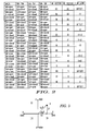
- the table illustrated in FIG. 2 reflects the sixteen possible switching states as vectors.
- the first column in the table represents the states (open/closed) of the first set of switching devices Sah, Sal.
- the second column in the table represents the states (open/closed) of the second set of switching devices Sbh, Sbl.
- the third column in the table represents the states (open/closed) of the third set of switching devices Sch, Scl.
- the fourth column in the table represents the states (open/closed) of the third set of switching devices Sdh, Sdl.
- the fifth and sixth columns reflect the sixteen vector states.
- the seventh column reflects the relationship between the current through the DC link (i_dc_link) and the currents i 1 and i2 through the phase windings W 1 and W2.
- i_dc_link current through the DC link
- i 1 and i2 currents i 1 and i2 through the phase windings W 1 and W2.
- the sixteen possible switching states there are twelve active vector states where current will flow through the DC link and four zero vector states (0000, 1100, 0011, 1111) where little or no current will flow through the DC link and only a DC offset current will be registered.
- vector 1001 includes a combination of i1-i2.
- the present invention uses PWM signals to control the states of the switching devices. By controlling the states of the switching devices, desired phase voltages may be applied to the phase windings W1 and W2 of the motor.
- FIG. 3 shows a typical inverter voltage space vector diagram for PWM operation.
- the vector diagram is divided into four sectors I-IV.
- the inverter or switching circuit When the inverter or switching circuit is driving the motor, the voltage space vector V ⁇ will rotate at the same speed as the motor. A voltage space vector will fall within one of the sectors or fall on one of the active vectors. If the voltage space vector falls within a sector, two adjacent vectors are chosen. For example, FIG. 3 illustrates a voltage space vector V ⁇ falling within sector I.
- V ⁇ V 1 ′ + V 2 ′
- V 1 ′ V 1 * ( t 1 / Tp )
- V 2 ′ V 2 * ( t 2 / Tp )
- t1 is a first time period during which vector V1 is applied
- t2 is a second time period during which vector V2 is applied
- Tp is a full pulse width modulated cycle or period (typically fifty microseconds).
- the amplitude of the voltage space vector V ⁇ can be described by a modulation index.
- FIG. 4 a timing diagram is shown for naturally symmetric PWM signals.
- Each timing diagram shows the voltage pulse trains applied to the switching devices to produce voltages Va, Vb, Vc, Vd on the windings W1, W2 of the motor that correspond to the two phases of the motor over a single pulse width modulation cycle or period Tp.
- the pulse timing can be driven by a simple ramp signal 40 that operates on various thresholds 42. For example, a Vc threshold on a downward ramp signal will apply the voltage Vc, and the same Vc threshold on an upward ramp signal will remove the voltage Vc. Thresholds Va, Vb and Vd work similarly in this symmetric manner.
- the pulse width modulated signal is not constant. Rather, the signal is on for a part of the period and off for another part of the period.
- the high state of the voltage pulse train indicates that an upper switching device Sah, Sbh, Sch, Sdh is closed (and a corresponding lower switching device Sal, Sbl, Scl, Sdl is open by a corresponding opposite voltage pulse train (not shown)).
- the low state of the voltage pulse train indicates that an upper switching device Sah, Sbh, Sch, Sdh is open (and a corresponding lower switching device Sal, Sbl, Scl, Sdl is closed by a corresponding opposite voltage pulse train (not shown)).
- the patterns of the voltage pulse trains are symmetrical to a center axis that represents a half pulse width period tp.
- any of sample points S1-S4 can be taken to determine current i2 in winding W2 (at vector 0010 or vector 1110), but it is not possible to independently find the current i1 in winding W 1 inasmuch as none of the vectors contain i 1 solely. Indeed, during the vectors 0000 and 1111 there is no current is passing through DC link (zero vector states). However, in half the time period Tp the active vector V2 is applied. In other words, a current will pass through the DC link during the vectors 00010 and 1110.
- a current through the corresponding winding may be measured or sampled (S1-S4).
- the time period necessary to obtain an accurate sample measurement is about two microseconds, preferably taken in the middle of the pulse width. Therefore, a sampling window of about four microseconds is desired
- FIG. 5 shows one solution to the problem of obtaining both i and i2 measurements involving shifting of the pulse train. This can be accomplished by manipulating then switching thresholds for Va and Vb during the PWM cycle as shown. For example, threshold Va1 is used to apply voltage Va, and threshold Va2 is used to remove voltage Va. Similarly, threshold Vb1 is used to apply voltage Vb, and threshold Vb2 is used to remove voltage Vb. In this case, a sample S 1 can be taken during vector 1000 (or sample S3 during vector 0111) to determine i1 and samples S2 or S4 can be taken to determine i2 as before. However, it is very difficult to manage the four PWM outputs and changing thresholds in this solution.
- FIGs. 6 and 7 show a further solution to mitigate the problems inherent in the solution of FIG. 5, by using a phase grounding approach (FIG. 6) and then introducing small active states (FIG. 7) for measurement.
- Phase grounding is to choose vector 0000 for zero-vector synthesis by turning-on the corresponding lower devices.
- the advantage of this is the reduction of switching and the switching losses inherent therein.
- any coupling interaction between windings is reduced and there is no need to use a gate drive with 100% duty cycle capability.
- the only non-zero active vector is Vc.
- Other vectors Va, Vb and Vd are zero vectors.
- Va, Vb and Vd are at virtual grounds (i.e.
- one or more vectors can be artificially introduced to measure i1 as shown in FIG. 7.
- two vectors are introduced within the 0010 vector (resulting after the merging of the Vc ON states) of FIG. 6.
- the two introduced vectors are of a minimal time period (e.g. four microseconds) that is sufficient to provide an accurate measurement.
- Va is turned on (Vb off) to drive a current i 1 through W 1 so that a sample can be measured.
- just turning Va ON would result in a 1010 vector, which does not isolate i1.
- a 1011 vector will isolate i1 for measurement. Therefore, Vd can be turned on for the sample S2.
- Vc-Vd Vc-Vd
- Vc-Vd current +i 1 is introduced into winding W1.
- an equivalent -il current is introduced (shown as sample S3).
- Va is switched OFF (by the change from a downward to upward ramp indication)
- Vb is switched ON (also by the change from a downward to upward ramp indication)
- Vd is left ON, with the resulting 0111 vector providing a -il current in winding W1.
- il (S3+S2)/2.
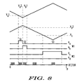
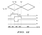
- the active states and sampling between the windings are removed from each other. This can be done by providing two PWM ramp signals that are separated by 180 degrees, as shown in FIG. 8.
- This embodiment has several advantages. First, only one W2 active vector is needed which reduces switching losses. Second, the active states are well separated which not only reduces potential winding coupling, but also leaves room for the active vectors to widen (as motor drive requires) without interacting, i.e. increase dynamic range. In addition, the sampling points can remain fixed. As a result, this embodiment provides accurate two-phase motor measurements with a single current sensor for all the light and medium duty-cycle requirements for a two-phase motor.
- FIG. 9 shows the two-phase motor under heavy load with overlapping active states (both ramps shown together).
- W2 is being driven for a large majority of the duty cycle.
- i1 can be accurately measured during vector 1000, and i2 can be measured anytime during sample S4.
- the period for sample S2 is less than sufficient (e.g. four microseconds)
- an accurate measurement for i1 can not be made.
- the motor control algorithm will limit voltage output to guarantee that both active voltage vectors cannot be at 100% duty cycle.
- the minimum sampling window will hereinafter be referred to as Wmin.
- FIG. 10 shows the very-light load case where one of the windings is powered for a very short time (e.g. less than four microseconds), wherein an accurate sample can not be obtained.
- something similar to the embodiment for FIG. 7 can be used wherein one of the vectors (0010) is widened while an artificial vector (0001) is introduced, by driving Vd, to balance out the current inequity caused by widening the short vector.
- Vc ON time for active state vector 0010 is only three microseconds, then it is known that an accurate sample for S3 can not be obtained.
- One solution would be to spread the Vc ON time for another one microsecond (arrow) and apply a balancing one microsecond Vd On time (shown as sample S4.
- sample S4 it is very difficult to control a one microsecond pulse in the PWM system.
- Vd ON time is also at least four microseconds for better control. This then requires that the sample S3 be spread not an addition one microsecond, but an additional four microseconds (seven microseconds total). Not only does this provide more stable operation, the presence of the new 0010 and 0001 vectors allows at least two samples (S2, S4) to be taken and averaged for a more consistent measurement result for current i2.
- the present invention takes into account these different cases.
- the PWM signals are applied in certain ways to allow a sufficient sampling window (or time period) for measuring a current across the sensor on the DC link.
- a sufficient sampling window or time period for measuring a current across the sensor on the DC link.
- each case is identified and then appropriate shifts or modifications to the PWM signals are made by the controller of the system based on the identified case.
- the 0000 vector or zero voltage vector can be measured for zero-amp calibration and to take into account resistor and amplifier temperature coefficient drift.
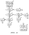
- the present invention describes a method for measuring the current in each phase of a two-phase motor by a single sensor, the motor being controlled by a plurality of switching devices that receive pulse width modulation signals from a controller.
- a first step 80 includes providing two ramp signals for a pulse width modulation controller for controlling the switches. The ramp signals being approximately one half cycle out of phase, with the first ramp signal for controlling the first set of switches and the second ramp signal for controlling the second set of switches.
- the dual ramp signals ensure that the distribution of pulses used to control one winding are approximately one-half of a PWM cycle away from the pulse distribution for the other winding.
- a next step 90 includes gating the first and second set of switches using the respective ramp signals. This results in a first voltage pulse train Vab, and second voltage pulse train Vcd associated with the two windings W1, W2 of the motor, respectively.
- the Vab and Vcd pulse trains provide a relative timing offset of approximately one-half cycle between the pulse width modulation signals driving the first and second windings of the motor.
- a next step includes the reading 100 a modulation index (i.e. duty cycle) for the pulse width modulation signals for one pulse width modulation cycle from a motor drive control.
- this step reads a first duty cycle of a first drive signal for the first winding and a second duty cycle of a second drive signal for the second winding.
- the method uses the modulation index to determine how to when and how to modify the voltage pulse trains.
- First and second sampling windows are time periods defined within pulse train of the cycle that may allow certain current measurements to be taken. Preferably, measurement samples are taken in the middle of a sampling window. For adequate current measurement, these windows should be greater than a minimum window, Wmin. For control purposes, at least one of these windows should be less than 100%-Wmin, or Wmax.
- a next step includes configuring 104, 110, 114, 116, 118 the timing of the pulse width modulation signals to provide at least one timing window wherein at least of one of the windings of the motor is being driven while the other winding is not being driven, such that a single current sensor can sample the current of the at least one of the windings during the at least one timing window.
- a first embodiment 104 when both the first and second sampling windows are less than the minimum sampling window (resulting in no overlapping) 102, artificial voltage vectors are introduced to add to the sampling period for both Vab and Vcd to provide sufficient sampling time.
- artificial and adjacent vectors 1000 and 0100 vectors are introduced to provide at least one sample for i1 (as was demonstrated for Vab in FIG. 8). This is also the case where Vab is non-existent (Vab has zero duty cycle), with artificial vector 1000 being added to the existing 1000 vector and vector 0100 being placed adjacent (similar to what was demonstrated for Vcd in FIG. 10).
- Vcd artificial and adjacent vectors 0010 and 0001 vectors are introduced to add to the sampling period to provide at least one sample for i2 (similar to what was demonstrated for Vab in FIG. 8). This is also the case where Vcd is non-existent (Vcd has zero duty cycle), with artificial vector 0010 being added to the existing 0010 vector and vector 0001 being placed adjacent (as was demonstrated for Vcd in FIG. 10).
- i 1 and i2 are isolated and can be sampled individually.
- i1 can be sampled during vector 1000 (as was demonstrated for Vab in FIG. 10)
- i2 can be sampled during vectors 0010 (as was demonstrated for Vcd in FIG. 8).
- a third embodiment 114 when both sampling windows are greater than Wmin 106, and the first sampling window is greater than Wmax, and the second sampling window is less than Wmax 108, the current of the first sample can not be obtained, but the current of the second sample can be obtained by itself. In this case, the first sample will contain the sum of the winding currents, and the second current is subtracted from this sum to obtain the first current (as was demonstrated in FIG. 9).
- a fourth embodiment 116 when the first sampling window is less than Wmin, and the second sampling window is greater than Wmin 106, and both sampling windows are less than 100%-3*Wmin (hereinafter Wmax3) 112, than artificial vectors are introduced for the first sampling window (e.g. Vcd) to provide sufficient sampling time.
- Vcd artificial, extended (3x)
- adjacent vectors 0010 and 0001 vectors can be introduced to add to the sampling period to provide at least one sample for i2 (as was demonstrated for FIG. 10).
- artificial, extended (3x) and adjacent vectors 1000 and 0100 vectors can be introduced to add to the sampling period to provide at least one sample for i 1 (as was demonstrated for Vcd in FIG. 10).
- a fifth embodiment 118 when the first sampling window is less than Wmin, and the second sampling window is greater than Wmin 106, and at least one of the sampling windows is greater than 100%-3*Wmin 112, then artificial vectors are introduced for the first sampling window (e.g. Vcd) to provide sufficient sampling time.
- Vcd first sampling window
- artificial and adjacent vectors 1011 and 0111 vectors are introduced to add to the sampling period to provide at least one sample for i1 (as was demonstrated for FIG. 7 wherein the W2-11 vector is introduced along with the two active W 1 vectors). This is subtracted from the second sample, which contains the sum of the currents, to obtain the sample for i2.
- another option is to create a sub-case where the W2 null vector (11) is aligned with only one of the two introduced W 1 vectors .
- the present invention also provides technique for abnormal operation for the motor. For example, if one of the windings is shorted (or the associated switches shorted) and turned OFF, breaking torque for the motor will come from free-wheeling, recirculating current only. However, it will still be possible to use the common shunt current sensor to read the current from the other good winding. In addition, is desirable that the controller incorporate delay compensation between the controller and the power stage. This will provide compensation for the propagation delay between these stages.
- a next step 90 includes gating the first and second set of switches using the respective ramp signals in accordance with the modifications of selected embodiment above.
- a final step 95 includes sampling the current in at least one of the windings in the defined sampling windows to determine the current in both windings, as detail previously.
Landscapes
- Engineering & Computer Science (AREA)
- Power Engineering (AREA)
- Control Of Ac Motors In General (AREA)
- Inverter Devices (AREA)
- Control Of Direct Current Motors (AREA)
- Power-Operated Mechanisms For Wings (AREA)
Applications Claiming Priority (1)
| Application Number | Priority Date | Filing Date | Title |
|---|---|---|---|
| US10/889,490 US7109742B2 (en) | 2004-07-12 | 2004-07-12 | Current sensing in a two-phase motor |
Publications (2)
| Publication Number | Publication Date |
|---|---|
| EP1617555A2 true EP1617555A2 (de) | 2006-01-18 |
| EP1617555A3 EP1617555A3 (de) | 2008-01-16 |
Family
ID=35169758
Family Applications (1)
| Application Number | Title | Priority Date | Filing Date |
|---|---|---|---|
| EP05254355A Withdrawn EP1617555A3 (de) | 2004-07-12 | 2005-07-12 | Stromfühlung in einem Zweiphasenmotor |
Country Status (4)
| Country | Link |
|---|---|
| US (3) | US7109742B2 (de) |
| EP (1) | EP1617555A3 (de) |
| JP (1) | JP4284306B2 (de) |
| CN (1) | CN100350734C (de) |
Cited By (4)
| Publication number | Priority date | Publication date | Assignee | Title |
|---|---|---|---|---|
| WO2008055741A1 (de) | 2006-11-07 | 2008-05-15 | Robert Bosch Gmbh | Verfahren und vorrichtung zur strommessung in einem insbesondere mehrphasigen stromnetz |
| WO2012107325A1 (de) * | 2011-02-10 | 2012-08-16 | Robert Bosch Gmbh | Verfahren und vorrichtung zur strommessung |
| WO2013000632A3 (de) * | 2011-06-28 | 2013-05-23 | Robert Bosch Gmbh | Verfahren und vorrichtung zur messung von phasenstromangaben und einer erregerstromangabe in einer elektrisch erregten elektrischen maschine |
| KR20150013150A (ko) * | 2012-05-04 | 2015-02-04 | 이턴 코포레이션 | 가변 속도 드라이브 내 지락 검출 및 가변 속도 드라이브 보호를 위한 시스템 및 방법 |
Families Citing this family (25)
| Publication number | Priority date | Publication date | Assignee | Title |
|---|---|---|---|---|
| US7414425B2 (en) * | 2004-05-10 | 2008-08-19 | Temic Automotive Of North America, Inc. | Damping control in a three-phase motor with a single current sensor |
| JP4589093B2 (ja) * | 2004-12-10 | 2010-12-01 | 日立オートモティブシステムズ株式会社 | 同期モータ駆動装置及び方法 |
| EP1883787A4 (de) * | 2005-05-25 | 2013-12-18 | Continental Automotive Canada Inc | Doppelpolmagnetstruktur mit zwei um 90 grad phasenverschobenen magneten zur positionserfassung in einem stellglied |
| US7808201B2 (en) * | 2005-06-09 | 2010-10-05 | International Rectifier Corporation | Sensorless field oriented controller for two-phase motor |
| DE102005062759A1 (de) * | 2005-12-28 | 2007-07-05 | Robert Bosch Gmbh | Verfahren und Vorrichtung zur Strommessung |
| JP5058554B2 (ja) * | 2006-10-16 | 2012-10-24 | 株式会社ジェイテクト | 電動パワーステアリング装置 |
| JP5252475B2 (ja) * | 2007-11-06 | 2013-07-31 | オムロンオートモーティブエレクトロニクス株式会社 | 多相電動機の制御装置 |
| DE102010001241A1 (de) * | 2009-04-01 | 2010-10-07 | Robert Bosch Gmbh | Elektronisch kommutierter Elektromotor mit einer Notlaufeigenschaft |
| JP5238596B2 (ja) * | 2009-04-27 | 2013-07-17 | 株式会社日本自動車部品総合研究所 | 回転電機の放電量測定装置および放電量測定方法 |
| TWI391685B (zh) * | 2009-10-16 | 2013-04-01 | Ind Tech Res Inst | 繞線製品檢測機台及其層間短路之檢測方法 |
| JP5372705B2 (ja) | 2009-11-04 | 2013-12-18 | 株式会社日立産機システム | 電力変換装置 |
| DE102010001181A1 (de) * | 2010-01-25 | 2011-07-28 | Robert Bosch GmbH, 70469 | Verfahren und Vorrichtung zur Strommessung in einem mehrphasigen Stromnetz |
| JP5435310B2 (ja) * | 2011-09-08 | 2014-03-05 | 株式会社デンソー | 回転電機制御装置、および、これを用いた操舵制御システム |
| CN103023287B (zh) * | 2013-01-14 | 2014-10-29 | 黑龙江大学 | 单相感应电机的独立电源式空间矢量逆变电路调制方法 |
| CN103439657B (zh) * | 2013-07-23 | 2016-05-11 | 南京康尼机电股份有限公司 | 交流伺服电机传动参数检测方法及其在故障检测中的应用 |
| US9450520B2 (en) * | 2014-12-15 | 2016-09-20 | Analog Devices, Inc. | Space vector pulse modulation based motor driver |
| US9584043B2 (en) * | 2015-02-28 | 2017-02-28 | Rockwell Automation Technologies, Inc. | Inverter phase current reconstruction apparatus and methods |
| JP6641794B2 (ja) * | 2015-08-28 | 2020-02-05 | 株式会社リコー | モータ駆動装置、モータ制御装置、搬送装置及びモータ駆動方法 |
| DE102016204854A1 (de) * | 2016-03-23 | 2017-09-28 | Zf Friedrichshafen Ag | Ermittlung eines Kurzschlussstroms in den Phasen einer mittels eines Wechselrichters angesteuerten E-Maschine |
| DE102017205385A1 (de) * | 2017-03-30 | 2018-10-04 | Zf Friedrichshafen Ag | Verfahren zum Kalibrieren eines Umrichters für eine elektrische Maschine, Steuergerät und Steuermodul |
| DE102019217747A1 (de) * | 2019-11-18 | 2021-05-20 | Rolls-Royce Deutschland Ltd & Co Kg | Ermitteln eines Inverterkurzschlusses zwischen zwei Phasen |
| KR102824482B1 (ko) * | 2020-06-10 | 2025-06-24 | 엘지전자 주식회사 | 2상 모터 어셈블리 |
| US20240195333A1 (en) * | 2022-12-09 | 2024-06-13 | Steering Solutions Ip Holding Corporation | Systems and methods for active damping in a steer-by-wire handwheel actuator system |
| JP2025099615A (ja) * | 2023-12-22 | 2025-07-03 | 三菱電機株式会社 | モータ電流検出方法、モータ制御装置、モータ装置、換気扇、及び送風機 |
| CN118646318B (zh) * | 2024-08-16 | 2024-12-20 | 奥克斯空调股份有限公司 | 一种电机三相控制脉冲生成方法、存储介质和空调器 |
Citations (1)
| Publication number | Priority date | Publication date | Assignee | Title |
|---|---|---|---|---|
| US5656910A (en) | 1993-11-19 | 1997-08-12 | Sgs-Thomson Microelectronics Gmbh | Driver circuit for a stepping motor |
Family Cites Families (26)
| Publication number | Priority date | Publication date | Assignee | Title |
|---|---|---|---|---|
| DE3526007C2 (de) * | 1984-07-20 | 1999-11-11 | Papst Licensing Gmbh & Co Kg | Schaltungsanordnung zum Ansteuern eines kollektorlosen, an ein Gleichstromnetz angeschlossenen Gleichsstrommotors |
| JPH0824435B2 (ja) | 1985-03-07 | 1996-03-06 | 日本ビクター株式会社 | 直流ブラシレスモ−タ |
| JP2614454B2 (ja) * | 1987-07-29 | 1997-05-28 | 東レ・ダウコーニング・シリコーン株式会社 | 正帯電性樹脂粉末の流動性向上剤 |
| IT1222824B (it) * | 1987-10-05 | 1990-09-12 | Sgs Microelettrica Spa | Circuito di controllo di commutazione di corrente in carichi induttivi multipli,a singolo sensore di corrente,particolarmente per avvolgimenti di motori a passo |
| CN2075400U (zh) * | 1990-08-16 | 1991-04-17 | 中国科学院三环新材料研究开发公司 | 无位置传感器式两相无刷电动机 |
| US5216347A (en) * | 1991-03-29 | 1993-06-01 | Sgs-Thomson Microelectronics, Inc. | Stepper motor control system |
| US5134349A (en) | 1991-05-28 | 1992-07-28 | Kruse David L | Two-phase brushless dc motor controller |
| JPH05316795A (ja) | 1992-05-13 | 1993-11-26 | Hitachi Ltd | 2相モータの電流検出法 |
| US5313148A (en) * | 1992-08-21 | 1994-05-17 | Alliedsignal Inc. | Electronically commutated two-axis gyro control system |
| US5274317A (en) | 1992-11-12 | 1993-12-28 | General Motors Corp. | Single sensor current control of a multiple phase AC machine |
| JP3354633B2 (ja) * | 1993-06-25 | 2002-12-09 | 富士通テン株式会社 | ステッピングモータ駆動装置 |
| JPH08317687A (ja) * | 1995-05-19 | 1996-11-29 | Nippon Densan Corp | モータの駆動回路 |
| DE19519370A1 (de) * | 1995-05-26 | 1996-11-28 | Philips Patentverwaltung | Schaltungsanordnung zum Speisen eines Zweiphasen-Asynchronmotors |
| EP0772296B1 (de) * | 1995-10-31 | 2003-04-02 | Consorzio per la Ricerca sulla Microelettronica nel Mezzogiorno - CoRiMMe | Rückgewinnung der Laufzeitverzögerung in einer Pulsbreitenmodulatorschaltung |
| US5719519A (en) | 1995-11-20 | 1998-02-17 | Motorola, Inc. | Circuit and method for reconstructing a phase current |
| JP3395071B2 (ja) * | 1996-04-25 | 2003-04-07 | ミネベア株式会社 | モータ構造 |
| JPH10191696A (ja) * | 1996-12-26 | 1998-07-21 | Toshiba Corp | ステッピングモータ駆動装置 |
| US5877608A (en) * | 1997-11-21 | 1999-03-02 | Philips Electronics North America Corporation | Current regulated multiphase motor driver with a common current sense element |
| JPH11289797A (ja) | 1998-04-02 | 1999-10-19 | Canon Inc | 2相ステッピングモーターの駆動方法 |
| DE19836129A1 (de) * | 1998-08-10 | 2000-02-24 | Siemens Ag | Schaltungsanordnung zum Generieren einer virtuellen Masse als gemeinsames Bezugspotential für eine Abgassonde in einem Kraftfahrzeug |
| GB9920988D0 (en) | 1999-09-07 | 1999-11-10 | Trw Lucas Varity Electric | Motor control |
| US6586898B2 (en) * | 2001-05-01 | 2003-07-01 | Magnon Engineering, Inc. | Systems and methods of electric motor control |
| US6735537B2 (en) | 2002-03-15 | 2004-05-11 | Motorola, Inc. | Procedure for measuring the current in each phase of a three-phase device via single current sensor |
| EP1519479B1 (de) | 2003-09-24 | 2010-01-27 | Japan Servo Co. Ltd. | Schrittmotorantrieb |
| US7023171B2 (en) * | 2003-11-12 | 2006-04-04 | Ut-Battelle Llc | Integrated inverter for driving multiple electric machines |
| US7193388B1 (en) * | 2006-02-02 | 2007-03-20 | Emerson Electric Co. | Offset PWM signals for multiphase motor |
-
2004
- 2004-07-12 US US10/889,490 patent/US7109742B2/en not_active Expired - Lifetime
-
2005
- 2005-07-12 JP JP2005202667A patent/JP4284306B2/ja not_active Expired - Fee Related
- 2005-07-12 CN CNB2005100836777A patent/CN100350734C/zh not_active Expired - Fee Related
- 2005-07-12 EP EP05254355A patent/EP1617555A3/de not_active Withdrawn
- 2005-12-29 US US11/322,007 patent/US7339394B2/en not_active Expired - Fee Related
-
2006
- 2006-02-16 US US11/355,708 patent/US7239168B2/en not_active Expired - Lifetime
Patent Citations (1)
| Publication number | Priority date | Publication date | Assignee | Title |
|---|---|---|---|---|
| US5656910A (en) | 1993-11-19 | 1997-08-12 | Sgs-Thomson Microelectronics Gmbh | Driver circuit for a stepping motor |
Cited By (7)
| Publication number | Priority date | Publication date | Assignee | Title |
|---|---|---|---|---|
| WO2008055741A1 (de) | 2006-11-07 | 2008-05-15 | Robert Bosch Gmbh | Verfahren und vorrichtung zur strommessung in einem insbesondere mehrphasigen stromnetz |
| US8421394B2 (en) | 2006-11-07 | 2013-04-16 | Robert Bosch Gmbh | Method and apparatus for current measurement in an electrical network, in particular a multiphase electrical network |
| WO2012107325A1 (de) * | 2011-02-10 | 2012-08-16 | Robert Bosch Gmbh | Verfahren und vorrichtung zur strommessung |
| WO2013000632A3 (de) * | 2011-06-28 | 2013-05-23 | Robert Bosch Gmbh | Verfahren und vorrichtung zur messung von phasenstromangaben und einer erregerstromangabe in einer elektrisch erregten elektrischen maschine |
| CN103620943A (zh) * | 2011-06-28 | 2014-03-05 | 罗伯特·博世有限公司 | 在电激励的电机中测量相电流数据和激励电流数据的方法和装置 |
| CN103620943B (zh) * | 2011-06-28 | 2016-12-21 | 罗伯特·博世有限公司 | 在电激励的电机中测量相电流数据和激励电流数据的方法和装置 |
| KR20150013150A (ko) * | 2012-05-04 | 2015-02-04 | 이턴 코포레이션 | 가변 속도 드라이브 내 지락 검출 및 가변 속도 드라이브 보호를 위한 시스템 및 방법 |
Also Published As
| Publication number | Publication date |
|---|---|
| EP1617555A3 (de) | 2008-01-16 |
| CN1725624A (zh) | 2006-01-25 |
| US7239168B2 (en) | 2007-07-03 |
| JP4284306B2 (ja) | 2009-06-24 |
| CN100350734C (zh) | 2007-11-21 |
| US20060103417A1 (en) | 2006-05-18 |
| US7339394B2 (en) | 2008-03-04 |
| US20060125513A1 (en) | 2006-06-15 |
| US7109742B2 (en) | 2006-09-19 |
| JP2006034093A (ja) | 2006-02-02 |
| US20060006899A1 (en) | 2006-01-12 |
Similar Documents
| Publication | Publication Date | Title |
|---|---|---|
| US7339394B2 (en) | Current sensing in a two-phase motor | |
| Cho et al. | A three-phase current reconstruction strategy with online current offset compensation using a single current sensor | |
| US7977898B2 (en) | Current sensing for a multi-phase DC/DC boost converter | |
| US4777578A (en) | Integrated current sensor torque control for ac motor drives | |
| CN101958686B (zh) | 无传感器转子角位置估计的方法、系统和设备 | |
| US8138697B2 (en) | Sensorless speed detection during zero vector | |
| EP2120323B1 (de) | Strangstrommessungen an einer Drehstrombrücke mit einem einzigen, gemeinsamen Stromsensor im Gleichspannungszwischenkreis | |
| KR101368707B1 (ko) | 다상 전기 시스템에서의 전류 측정 방법 및 장치 | |
| KR101907899B1 (ko) | 3상 인버터 전압 이용률 증대 장치 | |
| JPH09331682A (ja) | 電力変換器 | |
| Schellekens et al. | Dead-time compensation for PWM amplifiers using simple feed-forward techniques | |
| CN112953347A (zh) | 逆变器和用于测量电机中的相电流的方法 | |
| US6323609B1 (en) | Alternate high-side/low-side PWM operation of brushless motors | |
| Chakrabarti et al. | A current reconstruction algorithm for three-phase inverters using integrated current sensors in the low-side switches | |
| US11374521B2 (en) | Motor resistance and inductance values from initial position detection timing parameters | |
| HK1085848A (en) | Current sensing in a two-phase motor | |
| US12494725B2 (en) | High performance current sensing architecture for brushless motors | |
| Büyükkeleş et al. | Analysis and compensation of nonlinear effects in an inverter with power MOSFETs | |
| Xu et al. | Inverter nonlinearity compensation for open-winding machine with dual switching modes | |
| Lim et al. | Sensorless-FOC for PMSM With Single DC-Link Shunt | |
| KR102546525B1 (ko) | 싱글-션트 알고리즘을 고려한 3상 인버터 데드 타임 보상 장치 및 방법 | |
| Rebelo et al. | Development of a Modular Controller to Minimize Current Ripple in Low Inductance Coreless Permanent Magnet Motor | |
| Warmuth et al. | Novel Control Methodologies of Back-to-Back B6 Bridges for an Application-Related Stress Test Setup | |
| HK40121665A (zh) | 用於无刷电机的高性能电流感测架构 | |
| KR20060006639A (ko) | 인버터의 삼상 출력 전류를 측정하는 방법 |
Legal Events
| Date | Code | Title | Description |
|---|---|---|---|
| PUAI | Public reference made under article 153(3) epc to a published international application that has entered the european phase |
Free format text: ORIGINAL CODE: 0009012 |
|
| AK | Designated contracting states |
Kind code of ref document: A2 Designated state(s): AT BE BG CH CY CZ DE DK EE ES FI FR GB GR HU IE IS IT LI LT LU LV MC NL PL PT RO SE SI SK TR |
|
| AX | Request for extension of the european patent |
Extension state: AL BA HR MK YU |
|
| REG | Reference to a national code |
Ref country code: HK Ref legal event code: DE Ref document number: 1085848 Country of ref document: HK |
|
| PUAL | Search report despatched |
Free format text: ORIGINAL CODE: 0009013 |
|
| AK | Designated contracting states |
Kind code of ref document: A3 Designated state(s): AT BE BG CH CY CZ DE DK EE ES FI FR GB GR HU IE IS IT LI LT LU LV MC NL PL PT RO SE SI SK TR |
|
| AX | Request for extension of the european patent |
Extension state: AL BA HR MK YU |
|
| 17P | Request for examination filed |
Effective date: 20080714 |
|
| 17Q | First examination report despatched |
Effective date: 20080821 |
|
| AKX | Designation fees paid |
Designated state(s): AT BE BG CH CY CZ DE DK EE ES FI FR GB GR HU IE IS IT LI LT LU LV MC NL PL PT RO SE SI SK TR |
|
| RAP1 | Party data changed (applicant data changed or rights of an application transferred) |
Owner name: CONTINENTAL AUTOMOTIVE SYSTEMS, INC. |
|
| REG | Reference to a national code |
Ref country code: HK Ref legal event code: WD Ref document number: 1085848 Country of ref document: HK |
|
| RIC1 | Information provided on ipc code assigned before grant |
Ipc: H02P 7/282 20060101AFI20140228BHEP |
|
| GRAP | Despatch of communication of intention to grant a patent |
Free format text: ORIGINAL CODE: EPIDOSNIGR1 |
|
| INTG | Intention to grant announced |
Effective date: 20140611 |
|
| RIN1 | Information on inventor provided before grant (corrected) |
Inventor name: LIU, GUANG Inventor name: KURNIA, ALEXANDER Inventor name: DELARMINAT, RONAN P. |
|
| STAA | Information on the status of an ep patent application or granted ep patent |
Free format text: STATUS: THE APPLICATION IS DEEMED TO BE WITHDRAWN |
|
| 18D | Application deemed to be withdrawn |
Effective date: 20141022 |