EP1617699A2 - Dispositif d'affichage à écran plat,support et dispositif haut-parleur - Google Patents
Dispositif d'affichage à écran plat,support et dispositif haut-parleur Download PDFInfo
- Publication number
- EP1617699A2 EP1617699A2 EP05254090A EP05254090A EP1617699A2 EP 1617699 A2 EP1617699 A2 EP 1617699A2 EP 05254090 A EP05254090 A EP 05254090A EP 05254090 A EP05254090 A EP 05254090A EP 1617699 A2 EP1617699 A2 EP 1617699A2
- Authority
- EP
- European Patent Office
- Prior art keywords
- main body
- flat panel
- speaker
- panel display
- stand
- Prior art date
- Legal status (The legal status is an assumption and is not a legal conclusion. Google has not performed a legal analysis and makes no representation as to the accuracy of the status listed.)
- Withdrawn
Links
Images








Classifications
-
- H—ELECTRICITY
- H04—ELECTRIC COMMUNICATION TECHNIQUE
- H04N—PICTORIAL COMMUNICATION, e.g. TELEVISION
- H04N5/00—Details of television systems
- H04N5/64—Constructional details of receivers, e.g. cabinets or dust covers
- H04N5/655—Construction or mounting of chassis, e.g. for varying the elevation of the tube
-
- H—ELECTRICITY
- H04—ELECTRIC COMMUNICATION TECHNIQUE
- H04R—LOUDSPEAKERS, MICROPHONES, GRAMOPHONE PICK-UPS OR LIKE ACOUSTIC ELECTROMECHANICAL TRANSDUCERS; ELECTRIC HEARING AIDS; PUBLIC ADDRESS SYSTEMS
- H04R5/00—Stereophonic arrangements
- H04R5/02—Spatial or constructional arrangements of loudspeakers
-
- H—ELECTRICITY
- H04—ELECTRIC COMMUNICATION TECHNIQUE
- H04R—LOUDSPEAKERS, MICROPHONES, GRAMOPHONE PICK-UPS OR LIKE ACOUSTIC ELECTROMECHANICAL TRANSDUCERS; ELECTRIC HEARING AIDS; PUBLIC ADDRESS SYSTEMS
- H04R1/00—Details of transducers, loudspeakers or microphones
- H04R1/20—Arrangements for obtaining desired frequency or directional characteristics
- H04R1/22—Arrangements for obtaining desired frequency or directional characteristics for obtaining desired frequency characteristic only
- H04R1/28—Transducer mountings or enclosures modified by provision of mechanical or acoustic impedances, e.g. resonator, damping means
- H04R1/2807—Enclosures comprising vibrating or resonating arrangements
- H04R1/2815—Enclosures comprising vibrating or resonating arrangements of the bass reflex type
- H04R1/2819—Enclosures comprising vibrating or resonating arrangements of the bass reflex type for loudspeaker transducers
-
- H—ELECTRICITY
- H04—ELECTRIC COMMUNICATION TECHNIQUE
- H04N—PICTORIAL COMMUNICATION, e.g. TELEVISION
- H04N21/00—Selective content distribution, e.g. interactive television or video on demand [VOD]
- H04N21/40—Client devices specifically adapted for the reception of or interaction with content, e.g. set-top-box [STB]; Operations thereof
- H04N21/47—End-user applications
- H04N21/485—End-user interface for client configuration
-
- H—ELECTRICITY
- H04—ELECTRIC COMMUNICATION TECHNIQUE
- H04R—LOUDSPEAKERS, MICROPHONES, GRAMOPHONE PICK-UPS OR LIKE ACOUSTIC ELECTROMECHANICAL TRANSDUCERS; ELECTRIC HEARING AIDS; PUBLIC ADDRESS SYSTEMS
- H04R1/00—Details of transducers, loudspeakers or microphones
- H04R1/20—Arrangements for obtaining desired frequency or directional characteristics
- H04R1/22—Arrangements for obtaining desired frequency or directional characteristics for obtaining desired frequency characteristic only
- H04R1/28—Transducer mountings or enclosures modified by provision of mechanical or acoustic impedances, e.g. resonator, damping means
- H04R1/2807—Enclosures comprising vibrating or resonating arrangements
- H04R1/2815—Enclosures comprising vibrating or resonating arrangements of the bass reflex type
- H04R1/2823—Vents, i.e. ports, e.g. shape thereof or tuning thereof with damping material
- H04R1/2826—Vents, i.e. ports, e.g. shape thereof or tuning thereof with damping material for loudspeaker transducers
-
- H—ELECTRICITY
- H04—ELECTRIC COMMUNICATION TECHNIQUE
- H04R—LOUDSPEAKERS, MICROPHONES, GRAMOPHONE PICK-UPS OR LIKE ACOUSTIC ELECTROMECHANICAL TRANSDUCERS; ELECTRIC HEARING AIDS; PUBLIC ADDRESS SYSTEMS
- H04R2420/00—Details of connection covered by H04R, not provided for in its groups
- H04R2420/05—Detection of connection of loudspeakers or headphones to amplifiers
-
- H—ELECTRICITY
- H04—ELECTRIC COMMUNICATION TECHNIQUE
- H04R—LOUDSPEAKERS, MICROPHONES, GRAMOPHONE PICK-UPS OR LIKE ACOUSTIC ELECTROMECHANICAL TRANSDUCERS; ELECTRIC HEARING AIDS; PUBLIC ADDRESS SYSTEMS
- H04R2499/00—Aspects covered by H04R or H04S not otherwise provided for in their subgroups
- H04R2499/10—General applications
- H04R2499/15—Transducers incorporated in visual displaying devices, e.g. televisions, computer displays, laptops
Definitions
- the present invention relates to a flat panel display apparatus, stand and speaker apparatus.
- This flat panel display apparatus prepares an exclusively- designed stand to place and support thereon a flat panel display main body (Cite patent reference 1, for example).
- a low-pitched sound speaker (woofer) is prepared independently of a speaker built in the flat panel display main body, and this low-pitched sound speaker and the speaker built in the flat panel display main body are combined together to construct a sound system with a large sound volume.
- Embodiments of the present invention seek to provide a flat panel display apparatus in which a powerful sound system using a low-pitched sound speaker can be easily realized without requiring an extra space.
- embodiments of the present invention seek to provide a stand and a speaker apparatus for use with such a flat panel display apparatus.
- a flat panel display apparatus which is composed of a flat panel display main body having a speaker built therein and a stand for placing and supporting the flat panel display main body thereon, wherein the stand has installed therein a woofer which is located at the back of the flat panel display main body in the state in which the stand has the flat panel display main body placed thereon.
- a flat panel display apparatus which is composed of a flat panel display main body having a speaker built therein and a stand for supporting the flat panel display main body thereon, wherein the stand has supports extended along the back thereof from both ends of a holder portion on which the flat panel display main body is placed, a speaker enclosure having a woofer built therein being supported between the supports.
- a flat panel display apparatus which is composed of a flat panel display main body, a stand for placing and supporting the flat panel display main body thereon, the stand having a speaker built therein, wherein the flat panel display main body and the stand have a connecting portion therebetween to electrically connect the flat panel display main body and the speaker, the connecting portion having a structure in which a connector on the side of the flat panel display main body and a connector on the side of the stand are fitted into and jointed to each other and in which they are fitted into each other in such a manner that any one of the connectors is constantly urged against the connector of the other side by a resilient member.
- a flat panel display apparatus composed of a flat panel display main body having a speaker built therein and a stand for placing and supporting the flat panel display main body thereon, the stand having a low-pitched sound speaker built therein.
- This flat panel display apparatus includes a detecting means for detecting a connection mistake of a connecting portion which electrically connects the flat panel display main body and the low-pitched sound speaker, wherein if a connection mistake is detected by the detecting means, then a message indicative of a detected connection mistake is indicated on a screen of the flat panel display main body.
- a flat panel display apparatus which is composed of a flat panel display main body and a stand for placing and supporting the flat panel display main body thereon, wherein the stand includes a speaker enclosure to have a speaker built therein, the stand including a slide mechanism for adjusting the position of the speaker enclosure so that the position of the speaker enclosure can be varied relative to the flat panel display main body.
- a speaker apparatus in which a speaker enclosure with a speaker unit attached thereto has an opening portion, the opening portion is connected with one end of a bass reflex duct and the bass reflex duct is housed within the speaker enclosure, wherein the opening portion is opened on the plane perpendicular to the plane to which the speaker unit is attached, the bass reflex duct being extended in the direction perpendicular to the direction in which sound waves are radiated from the speaker unit.
- the speaker of the flat panel display main body and the low-pitched sound speaker of the stand are combined together to complete the powerful sound system with the large sound volume.
- the stand that supports the flat panel display main body has the low-pitched sound speaker built therein, it is possible to realize the sound system with the large sound volume without requiring an extra space.
- this low-pitches sound speaker is located at the optimum position of the back side of the flat panel display main body in the state in which the flat panel display main body is placed on the state, it is possible to easily construct the sound system with the large sound volume without a cumbersome work for selecting the place to install the low-pitched sound speaker.
- this low-pitched sound speaker is located at the back side of the flat panel display main body, the outside appearance of the flat panel display apparatus can be made neat and simple on the whole as it is seen from the front.
- the stand on which the flat panel display main body is placed has supports extended along the back side thereof and the speaker enclosure having the low-pitched sound speaker built therein is supported between the supports, the speaker enclosure can be made large in size to increase its volume, whereby the more powerful sound system with the heavy low-pitched sound can be realized.
- the display main body and the speaker are electrically connected with each other in the state in which the display main body is placed on the state, the display main body and the speaker can be electrically connected with each other without user's cumbersome connection work.
- the connector of one side is constantly urged against and fitted into the connector of the other side under spring force of the resilient member, the stable connected state can be maintained.
- the connectors can be prevented from being released from the engagement due to causes such as vibrations in the transportation and hence reliability in the connection can be guaranteed.
- connection mistake occurred when the flat panel display main body and the low-pitched sound speaker are not connected with each other correctly is detected and the message indicative of such connection mistake is indicated on the screen of the flat panel display main body, it is possible to avoid a user from continuing to use the flat panel display apparatus without consciousness of the connection mistake and hence the flat panel display apparatus can be used while its original sound performance can be demonstrated sufficiently.
- the position of the speaker enclosure can be slidably adjusted in response to the size of the flat panel display main body that is placed on the stand, when the external connection cord is connected to the terminal portion at the back side of the flat panel display main body, for example, the external connection cord can be smoothly connected to the terminal portion without being disturbed by the speaker enclosure.
- the speaker enclosure can be adjusted so as to be located at the optimum position considering sound effects.
- the speaker enclosure can be decreased in thickness and hence it is possible to provide the speaker apparatus suitable for use with electronic equipment such as the flat panel display apparatus of which thickness is very strongly requested to be decreased.
- Embodiments of the present invention relate to a flat panel display apparatus, a stand used by this flat panel display apparatus to support a flat panel display main body and a low-pitched sound speaker apparatus included in the flat panel display apparatus.
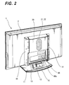
- FIG. 1 of the accompanying drawings is a perspective view showing a flat panel display apparatus according to an embodiment from the front side and FIG. 2 is a perspective view showing the flat panel display apparatus according to an embodiment from the back side.
- this flat panel display apparatus 1 is composed of a flat panel display main body (hereinafter simply referred to as a "display main body") 2 and a stand 10 to support this display main body 2 thereon.
- a flat panel display main body hereinafter simply referred to as a "display main body”
- a stand 10 to support this display main body 2 thereon.
- the display main body 2 has a large-size screen whose size fall within a range of from 37 to 50 inches provided on the front thereof.
- This display main body 2 is an ultra-thin type plasma display system television apparatus having a thickness of less than 10 cm.
- This display main body 2 has speakers 4 and 5 built in the left and right sides of the screen, and stereo sounds are emanated from the left and right speakers 4 and 5.
- the left and right speakers 4 and 5 of this display main body 2 are able to emanate mainly sounds of middle-pitched sound extent.
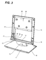
- the stand 10 to support the display main body 2 thereon is composed of a base plate 11 in contact with the floor surface, a leg member 12 erected on the base plate 11 and a holder plate 13 horizontally fixed to the leg member 12, and the display main body 2 is placed on and supported to this holder plate 13 such that the display main body 2 may stand upright.
- two supports 14 and 15 to support the back of the display main body 2 are extended in the vertical direction from both of right and left end portions of the holder plate 13 along the back side of the stand 10.
- the display main body 2 is fixed to the supports 14 and 15 by screws and thereby the display main body 2 is formed as one body with the stand 10.
- the leg portion 12 can be rotated in the left and right direction and it can also be inclined in the front and back direction relative to the base plate 11 upon adjustment. As a consequence, it is possible for a user to vary the angle of the screen of the display main body 2 freely.
- a speaker enclosure 20 having two speakers 21 and 22 built therein are attached to the flat panel display apparatus 1 according to this embodiment in such a manner that the speaker enclosure 20 may be supported between upper portions of the right and left supports 14 and 15 extended in the vertical direction along the back of this stand 10.
- the speakers 21 and 22 built in this speaker enclosure 20 are speakers for outputting low-pitched sounds (hereinafter referred to as "woofers") and they are electrically connected to the display main body 2 placed on the stand 10 to output heavy low-pitched sounds.
- the maximum outputs of the right and left speakers 4 and 5 of the display main body 2 are respectively 25W and maximum outputs of the woofers 21 and 22 at the back side of the stand 10 are respectively 50W.
- a sound system with a large volume of 100W in total may be completed.
- the woofers 21 and 22 are assembled into the stand 10 which supports the display main body 2, the sound system with the large volume can be realized without requiring an extra space. Further, since the woofers 21 and 22 are located at the optimum positions of the back side of the display main body 2 in the state in which the display main body 2 is placed on the stand 10, the woofers 21 and 22 can be located at the optimum positions without cumbersome selection of the places in which they should be installed and hence the sound system with the large sound volume can be constructed with ease.
- the speaker enclosure 20 can be formed large in size and it can be increased in volume so that a more powerful sound system with heavy low-pitched sounds can be realized.
- this flat panel display apparatus 1 has the arrangement in which the speaker enclosure 20 having the woofers 21 and 22 built therein is located on the back side of the stand 10, the outside appearance of this flat panel display apparatus 1 can become entirely neat and simple as it is seen from the front.
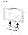
- two protruding members 17 and 18 are provided at both left and right ends of the holder plate 13 in the vertical direction.
- two insertion holes 7, 8 are formed at the center of a bottom portion 2a as shown in FIG. 4.
- the display main body 2 is placed on the holder plate 13 of the stand 10 from above as shown in FIG. 5 in such a manner that the insertion holes 7 and 8 may be fitted into the protruding members 17 and 18, whereby the protruding members 17 and 18 are inserted into and engaged with the insertion holes 7 and 8 to accurately position the display main body 2 and the stand 10.
- the display main body 2 and the stand 10 are integrated as one body by fixing the supports 14 and 15 to the display main body 2 with screws from the back side of the stand 10.
- This flat panel display apparatus 1 has the arrangement in which the display main body 2 can be electrically connected to the woofers 21 and 22 at the same time the display main body 2 is placed on the stand 10.
- FIG. 6 and 7 show the structure of that connecting portion.
- reference numeral 25 denotes a connector on the side of the display main body 2 and reference numeral 26 denotes a connector on the side of the stand 10.
- the connector 26 on the side of the stand 10 is fixed to and held on a holding plate 27 provided on the holder plate 13.
- the holding plate 27 has small protruded members 28 and 29 extended in the vertical direction from left and right sides of the connector 26.
- the display main body 2 has insertion holes 30 and 31 formed at left and right sides of the connector 25 on the bottom portion thereof.
- the holding plate 27 has lower protruding members 32 and 33 formed on its lower surface side opposite to the small protruding members 28 and 29.
- the lower protruding members 32 and 33 are fitted into holes 34 and 35 bored on the holder plate 13 and fixed with washer screws 36 and 37 so that the holding plate 27 is assembled to the holder plate 13 so as to become movable in the upper and lower direction.
- a leaf spring 38 is inserted between this holding plate 27 and the holder plate 13 as a resilient member, and hence the connector 26 is constantly supported with resiliency under spring force of this leaf spring 38 so that it can be elevated in unison with the holding plate 27.
- the small protruding members 28 and 29 of the supporting plate 27 are inserted into the insertion holes 30 and 31 of the display main body 2 and the connectors 25 and 26 are fitted into and connected with each other, thereby resulting in the display main body 2 and the woofers 21 and 22 being connected electrically.
- the connectors 25 and 26 can be fitted into and connected with each other reliably.
- the connector 25 is assembled on the side of the display main body 2 with small play in order to absorb an error occurred between it and the connector 26 on the side of the stand 10 when the connectors 25 and 26 are fitted into and connected with each other.
- the connector 26 on the side of the stand 10 is constantly urged against the connector 25 on the side of the display main body 2 under spring force of the leaf spring 38 and thereby the connector 26 can be prevented from being disengaged from the connector 25 and hence the connector 26 can be stably fitted into the connector 25.
- the connector 26 on the side of the stand 10 is fitted into the connector 25 on the side of the display main body 2 near the intermediate point of the range in which it can be moved in the upper and lower direction.
- the connector 26 on the side of the stand 10 can be fitted into the connector 25 on the side of the display main body 2 at the intermediate point in which the holding plate 27 is elevated from the holder plate 13 about 0.7 mm. Therefore, the connector 26 on the side of the stand 10 can be urged against the connector 25 on the side of the display main body 2 with a margin and hence the connector 26 can be fitted into the connector 25 more stably.
- the flat panel display apparatus since the flat panel display apparatus according to this embodiment has the structure in which the display main body 2 and the woofer 21 are electrically connected with each other at the same time the display main body 2 is placed on the stand 10, a user need not carry out a cumbersome connection work and the display main body 2 and the woofers 21, 22 can be electrically connected with each other reliably.
- the connector 26 on the side of the stand 10 is constantly urged against the connector 25 on the side of the display main body 2 under spring force of the leaf spring 38 and thereby they are fitted into each other, the stable connected state can be maintained.
- the connectors 26 and 26 can be prevented from being disengaged due to vibrations and the like produced upon transportation and hence reliability of the connection between the connectors 25 and 26 can be guaranteed.
- the flat panel display apparatus has the structure in which the connector 26 on the side of the stand 10 is constantly urged against the connector 25 on the side of the display main body 2 under spring force of the leaf spring 38 as described above, embodiments are not limited thereto and the flat panel display apparatus may have an opposite structure in which the connector 25 on the side of the display main body 2 is constantly urged against the connector 26 on the side of the stand 10 under spring force of the leaf spring 38.
- the flat panel display apparatus has the structure in which the display main body 2 and the woofers 21 and 22 are electrically connected with each other at the same time the display main body 2 is placed on the stand 10 as described above, when a connection mistake occurs in the connecting portion due to a cause such as an alien substance caught in the connecting portion, if a user continues to use this flat panel display apparatus without consciousness of the existence of such mistake, there is then a risk that original sound performance of this flat panel display apparatus will not be fully demonstrated upon use.
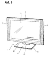
- connection mistake when a connection mistake occurs in the connecting portion, such connection mistake may be detected and an error message may be indicated on the screen.
- FIG. 8 is a schematic diagram showing an arrangement of a detecting means for detecting a connection mistake in the connecting portion of the flat panel display apparatus according to an embodiment.
- the connectors 25 and 26 includes four connection terminals 25a, 25b, 25c, 25c and 26a, 26b, 26c, 26d.
- connection terminals 25a, 25b and 26a, 26b are provided for use with audio signals, that is, these audio connection terminals 25a, 25b and 26a, 26b are used to connect an audio circuit 40 on the side of the display main body 2 side to the woofers 21 and 22 on the side of the stand 10 with each other, whereby audio signals are supplied from the audio circuit 40 to the woofers 21 and 22 and heavy low-pitched sounds are outputted from the woofers 21 and 22.
- connection terminals 25c, 25d and 26c, 26d are used to detect connections, that is, the connection terminals 25c and 25d are connected to a detecting circuit 41 on the side of the display main body 2, while the connection terminals 26c and 26d are short-circuited at a U-turn connection portion 26e within the stand 10.
- the detecting circuit 41 causes a detection electric current to flow through the connection terminals 25c, 25d and 26c, 26d and it can detect the connection state based on energized states of the connection terminals 25c, 25d and 26c, 26d. Specifically, when the connectors 25 and 26 are connected with each other correctly, the detection electric current flows through the connection terminals 25c, 25d and 26c, 26d. When the connectors 25 and 26 are not connected with each other correctly, no detection electric current flows through the connection terminals 25c, 25d and 26c, 26d. In this case, it is determined that a connection mistake occurred in the connecting portion.
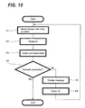
- a user places the display main body 2 on the stand 10 at a step 101. Then, when the user energizes the display main body 2 at a step 102, the detecting circuit 41 is operated to detect the connection state at a step 103. Then, control goes to the next decision step 104, whereat it is determined by the control apparatus whether or not the connecting portion is connected correctly. If the connecting portion is connected correctly as represented by a YES at the decision step 104, then the detection operation is ended.
- control goes to a step 105, whereat the character signal generating apparatus is energized to indicate a message on the screen 3 of the display main body 2. Then, control goes to a step 106, whereat the user who had visually confirmed this message on the screen 3 is turned off the power switch of the display main body 2. Then, control goes back to the step 101, whereat the user places the display main body 2 on the stand 10 one more time.
- connection mistake occurred when the display main body 2 and the woofers 21 and 22 are not correctly connected with each other is detected and the message indicative of such connection mistake is displayed on the screen 3, it is possible to avoid the user from continuing to use the flat panel display apparatus without consciousness of the connection mistake and therefore the original sound effect of this flat panel display apparatus can be fully demonstrated when the flat panel display apparatus is in use.
- a plurality of types of display main bodies of the same design with different sizes may be available as the display main body 2.
- Those different types of the display main bodies are roughly classified into small types (37-inch to 42-inch screen) and large types (50-inch screen).
- a terminal portion 44 with various external connection terminals 44a arrayed thereon is provided at the back side thereof.
- the position and size of this terminal portion 44 are different depending on the type of the display main body. More specifically, in the case of the large type display main body, the terminal portion 44 is located in the upper direction and it is formed large in size as compared with the small type display main body.
- the speaker enclosure 20 can be slid in the upper and lower direction upon adjustment.
- a back plate 46 is supported between guide rails 14A and 15A constructing the core materials of the supports extended on the holder plate 13 in the vertical direction such that it can be slid in the upper and lower direction.
- the speaker enclosure 20 is fixed to this back plate 46 by screws 53.
- the back plate 46 is brought in surface contact with the guide rails 14A and 15A at the end face portions of the respective sides and fastened to the end face portions by screws 48.
- Oblong holes 49 are formed in the guide rails 14A and 15A in the upper and lower direction and the back plate 46 is supported to the guide rails 14A and 15A by inserting the screws 48 into the oblong holes 49 so that the back plate 46 can be slid in the upper and lower direction.
- the speaker enclosure 20 can be slid in the upper and lower direction in the range in which the screws 48 are moved along the oblong holes 49, the speaker enclosure 20 can be fixed to the arbitrary slide position by fastening the screws 48, and the speaker enclosure 20 can be made again slidable by loosening the screws 48.
- the stand 10 can be applied to a plurality of kinds of the display main bodies 2 with different sizes. More specifically, when the display main body 2 is of the small type, the speaker enclosure 20 is located at the ordinary position as shown in FIG. 2. When the speaker enclosure 20 is of the large type, the speaker enclosure 20 is slid in the upper direction as shown in FIG. 12, whereby the user can connect the external connection cord to the terminal 44a on the terminal portion 44 without being disturbed by the speaker enclosure 20. Also, having considered the sound effect of this flat panel display apparatus, it is possible for the user to adjust the height position of the speaker enclosure 20 to the optimum height position.
- the speaker enclosure 20 is supported to the stand 10 through cushion materials 50.
- the stand 10 has a plurality of contracted portions 51 formed on the back plate 46, and the annular cushion materials 50 made of a suitable material such as elastomer are fitted into holes 51a formed at the centers of the contracted portions 51. Then, stems 52 projected from the speaker enclosure 20 are inserted into the center holes of the cushion materials 50 and secured by washer screws 53 as shown in FIG. 12.
- vibrations of heavy low-pitched sound transmitted from the speaker enclosure 20 can be effectively absorbed by the cushion materials 50.
- vibrations can be prevented from being transmitted to the display main body 2 and distortion and resonance of sound in the display main body 2 can be prevented so that clear sounds can be emanated from the speaker enclosure 20.
- FIG. 14 is a perspective view showing the inside of the enclosure main body of the speaker enclosure;
- FIG. 15 is a perspective view showing the state obtained before a lid is fitted into the enclosure main body;
- FIG. 16 is a perspective view showing the state obtained after the lid was fitted into the enclosure main body;
- FIG. 17A and 17B are cross-sectional views showing the states obtained before and after the lid is fitted into the enclosure main body, respectively;
- FIG. 18 is an explanatory diagram showing a main portion of FIG. 15 in an enlarged-scale;
- FIG. 19A and 19B are explanatory diagrams showing the main portions of FIG. 17A and 17B in an enlarged-scale;
- FIG. 20A and 20B are a front view of a bass reflex duct and a partly-cross-sectional bottom view of the bass reflex duct, respectively;
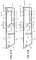
- FIG. 21A and 21B are explanatory diagrams showing the states obtained before and after the bass reflex duct is joined to a bass reflex duct connecting portion;
- FIG. 22 is a cross-sectional view showing a bass reflex duct connecting portion;
- FIG. 23A, 23B and 23C are explanatory diagrams showing another example of the layout of the bass reflex duct, respectively.
- a speaker apparatus whose speaker enclosure can be reduced in thickness and which is suitable for use with electronic equipment such as a flat panel display apparatus of which thickness should be very requested to be reduced can be realized by a simple arrangement.
- the speaker enclosure 20 is constructed as a casing composed of an enclosure main body 123 of which back portion is opened and a lid 124 detachably mounted to the back portion of this enclosure main body 123.
- the enclosure main body 123 includes an oblong rectangular front portion 123a, an upper surface portion 123b continued to the upper end edge of this front portion 123a, a lower surface portion 123c continued to the lower end edge of the front portion 123a and a left side portion 123d and a right side portion 123e.
- the enclosure main body 123 houses therein two speaker attachment portions 125a and 125b to attach woofers 21 and 22 which are two speaker units, two enclosure side connecting portions 128a and 128b to which two bass reflex ducts 126 and 127 are joined, duct supporting portions 129 and 129 to support the two bass reflex ducts 126 and 127 and two kinds of bosses 130a and 130b to attach the lid 124.
- the two speaker attachment portions 125a and 125b are located at the central portion of the inner surface of the front portion 123a in such a manner that they may be aligned in the upper and lower direction. A large number of through-holes are bored on the front surfaces of the two speaker attachment portions 125a and 125b in order to radiate sound waves to the outside, although not shown.
- the two woofers 21 and 22 are detachably fixed to the respective speaker attachment portions 125a and 125b by fixed screws, not shown.
- the two enclosure side connecting portions 128a and 128b are located on the lower surface portion 123c of the enclosure main boy 123 with a predetermined spacing therebetween in such a manner that they may become axial symmetry relative to the two woofers 21 and 22 in the right and left direction.
- the two enclosure side connecting portions 128a and 128b are formed of annular protruded portions which are slightly contracted in the inside. Holes opened at the centers of the two enclosure side connecting portions 128a and 128b construct opening portions 131 and 131 which are connected with holes of the two bass reflex ducts 126 and 127.
- the enclosure side connecting portions 128a and 128b have conic tapered portions 132 provided at their tip end portions. Duct side connecting portions 126a and 127a of the bass reflex ducts 126 and 127 are fitted into the two enclosure side connecting portions 128a and 128b.
- each of the bass reflex ducts 126 and 127 includes a pipe-like duct main body 133, a pair of fixed members 134 and 134 provided on the outer peripheral surface of the duct main body 133 and a stopper portion 135 provided at one end of the outer peripheral surface of the duct main body 133 in the axial direction.
- the duct main body 133 has a tapered receiving portion 136 with the same inclination angle, fitted into the two tapered portions 132 of the enclosure side connecting portions 128a and 128b, provided at the end portion of the stopper portion 135 side.
- the pair of fixed members 134 and 134 are formed to be symmetrical in the right and left direction in such a manner that they may be projected toward the outside of the diametrical direction in the intermediate portion of the axial direction of the duct main body 133.
- Each fixed member 134 includes an upper surface portion 134a and a lower surface portion 134b developed in the axial direction and which are spaced apart by a predetermined spacing in the upper and lower direction and an inclined surface portion 134c to join the upper surface portion 134a and the lower surface portion 134b with a proper inclination angle.
- a screw aperture 137 is bored on the upper surface portion 134a and this screw aperture 137 is extended in the axial direction of the duct main body 133.
- the bass reflex ducts 126 and 127 are fastened to and fixed to the enclosure main body 123 by the fixed screw 139 inserted into this screw aperture 137.
- the stopper portion 135 is provided for the purpose of properly positioning the bass reflex ducts 126 and 127 to the enclosure main body 123.
- the stopper portion 135 is formed of a rail-like portion having a U-like flat surface shape to form an engagement groove 140, and the engagement portion 140 has a tapered and widened introducing portion 140a provided at the entrance thereof as shown in FIG. 20B.
- a positioning member 141 provided on the lower portions of the enclosure side connecting portions 128a and 128b of the enclosure main body 123 is engaged with this engagement groove 140 as shown in FIG. 21A, 21B and FIG. 22.
- the bass reflex ducts 126 and 127 When this positioning member 141 is engaged with the engagement groove 140, the bass reflex ducts 126 and 127 can be prevented from being moved to the side of the enclosure side connecting portions 128a and 128b in the axial direction and the bass reflex ducts 126 and 127 can be prevented from being rotated.
- a pair of duct supporting portions 129 and 129 for supporting the bass reflex ducts 126 and 127 in the state in which the bass reflex ducts 126 and 127 are joined to the enclosure side connecting portions 128a and 128b are respectively formed on the inner surface of the front portion 123a of the enclosure main body 123 in an opposing relation to the pair of fixed members 134 and 134.
- Each duct supporting portion 129 includes a reinforcing member 142 projected to the side of the enclosure side connecting portions 128a and 128b, and an inclined surface receiving portion 142a inclined in the same direction in response to the inclined surface portion 134c of the fixed member 134 is provided at the upper end of the reinforcing member 142.
- the first boss 130a is provided at the intermediate portion of the inner surface of the upper surface portion 123b which is formed on the enclosure main body 123 with a small inclination angle in the upper direction.
- five first bosses 130b are provided in the lateral direction with a proper spacing therebetween.
- the second boss 130b is erected on the inner surface of the front portion 123a of the enclosure main body 123 along right and left side portions 123d and 123e.
- eight second bosses 130b are provided.
- Each of the bosses 130a and 130b has a screw hole opened on its supper surface.
- the lid 124 that can open and close the rear portion of the enclosure main body 123 having the above-mentioned arrangement has an arrangement shown in FIG. 15 to FIG. 17A and 17B.
- the lid 124 is formed of a plate material which can cover the whole of the rear portion of the enclosure main body 123.
- This lid 124 has screw holes 144 formed at its positions corresponding to the two kinds of bosses 130a and 130b of the enclosure main body 123 as shown in FIG. 15. Because all of these screw holes 144 are provided along the peripheral edge of the lid 124, a plurality of screw holes 145 (four screw holes 145 in this embodiment) is provided in order to fasten the central portion of the lid 124 to the side of the enclosure main body 123 by screws. Bosses corresponding to the screw holes 145 are not shown in FIG. 14.
- the lid 124 is fastened to the enclosure main body 123 by 17 fixed screws.
- identification marks 150 numbers in this embodiment which serves as standards for screwing work required when the lid 124 is assembled to the enclosure main body 123 are indicated near the respective screw holes 144 and 145.
- the identification marks 150 are indicated in the sequential order of screwing. First, the identification marks 150 are located in such a manner that they are started from the central portion of the outer peripheral edge to the corner portions, they being located at the central portion so that screwing work may be completed in the end.
- the lid 124 By tightening the fixed screws in accordance with the sequential order of the numbers of the identification marks 150, the lid 124 can be thoroughly fastened to the enclosure main body 123 in a well-balanced fashion and the whole of the outer peripheral edge of the lid 124 can be evenly made close to the whole of the outer peripheral edge of the enclosure main body 123, thereby resulting in airtightness being improved. It is preferable that this identification mark 150 should be impressed on the tip end of a projection pin which is used to extract the lid 124 from a metal mold for injection molding, the identification mark 150 being formed by using the mark of the projection pin. In this case, since special facilities and parts to impress the identification mark 150 need not be provided and the existing metal mold can be used, it is possible to prevent metal mold expense from being increased.
- the joined portion in which the enclosure main body 123 and the lid 124 are engaged with each other has an airtight structure of which cross-section is illustrated in FIG. 18 and FIG. 19A and 19B in an enlarged-scale.
- the enclosure main body 123 has a tapered groove 152 of V-like cross-section continuously formed around the whole periphery of its outer edge portion.
- the lid 124 has a tapered protruded rail 153 of V-like cross-section formed around the whole periphery of its outer edge portion.
- the tapered groove 152 which consists of an outside inclined surface 152a outwardly inclined and an inside inclined surface 152b formed of an inclined surface folded at substantially a right angle relative to the outside inclined surface 152a. Then, in response to these outside inclined surface 152a and inside inclined surface 152b, an outside inclined surface 153a and an inside inclined surface 153b formed of an inclined surface folded at substantially a right angle relative to this outside inclined surface 153a to constitute a tapered protruded rail 153. Airtightness of the lid 124 relative to the enclosure main body 123 can be extremely increased by fitting the tapered protruded rail 153 into the tapered groove 152.
- the speaker enclosure 20 having the above-mentioned arrangement can easily be assembled as follows, for example. As shown in FIG. 14, first, the woofers 21 and 22 that are the predetermined speaker units are attached to the two speaker attachment portions 125a and 125b of the enclosure main body 123 by screws.
- the two bass reflex ducts 126 and 127 are respectively assembled to the two enclosure side connecting portions 128a and 128b of the enclosure main body 123.
- This assembly work can be carried out as follows. First, as shown in FIG. 21A, a duct side connecting portion 126a (or 127a) provided at one end of the duct main body 133 is faced to an enclosure side connecting portion 128a (or 128b). At that time, respective lower surface portions 134b of a pair of fixed members 134, 134 provided on the respective bass reflex ducts 126 and 127 are brought in contact with the upper surfaces of a pair of duct supporting portions 129 and 129 of the enclosure main body 123.
- inclined surface portions 134c of the respective fixed members 134 are moved along an inclined surface receiving portion 142a of a reinforcing member 142 unitarily formed with the respective duct supporting portions 129, whereby the duct side connecting portion 126a (or 127a) of the bass reflex duct 126 (or 127) is fitted into the enclosure side connecting portion 128a (or 128b) as shown in FIG. 21B.
- positioning members 141 of the enclosure main body 123 are respectively engaged with engagement grooves 140 of stopper portions 135 of the respective bass reflex ducts 126 and 127.
- the bass reflex duct 126 (or 127) is given pressing force to press the bass reflex duct 126 (or 127) to the side of the enclosure side connecting portion 128a (or 128b).
- the bass reflex duct 126 (or 127) is connected to the enclosure side connecting portion 128a (or 128b) such that the duct side connecting portion 126a (or 127a) is urged against the enclosure side connecting portion 128a (or 128b) and thereby strongly fitted thereto.
- the lid 124 is fitted into the opening portion of the back side of the enclosure main body 123.
- the tapered protruding rail 153 provided on the outer peripheral edge of the inner surface of the lid 124 is engaged with the tapered groove 153 provided on the outer peripheral edge of the opening portion of the enclosure main body 123.
- the fixed screws are applied in the sequential order of the numbers indicated in the identification marks 150 and the lid 124 is fastened to and fixed to the enclosure main body 123 with a plurality of fixed screws.
- the tapered groove 152 formed of the V-like concave portion is provided on one of the whole periphery of the joined portion of the enclosure main body 123 and the lid 124 and the tapered protruding rail 153 formed of the V-like convex portion corresponding to the tapered groove 152 is provided on the other of the whole periphery of the joined portion, whereafter the tapered groove 152 and the tapered protruding rail 153 are fixed together with screws, the occurrences of the recess of the side between the portions fixed with the screws and distortion can be corrected so that the tapered groove 152 and the tapered protruding rail 153 can be made close to each other.
- the fixed screws are located at an interval as equal as possible so that fastening force may be applied equally. Also, since the identification marks 150 are provided such that the lid 124 is started to be fastened with screws from the center of the side of lid 124 to the corner portions thereof, an ideal airtight environment can be realized even by mass-production.
- a sealant is not required and hence a cost of assemblies can be decreased.
- this is desirable from an environmental problem standpoint and assembly properties and disassembly properties of the speaker enclosure can be improved.
- the fixed screws used to fix the lid 124 to the enclosure main body 123 are all housed within the holes 144 and 145 bored on the lid 124 and the head portions of the fixed screws are not exposed on the surface of the lid 124, the screw heads can be prevented from being exposed from an appearance standpoint and a stable fastened state between the lid 124 and the enclosure main body 123 can be obtained.
- the speaker apparatus having the above-mentioned arrangement is able to radiate sound waves of the bass register as follows. More specifically, a part of sounds from the two woofers 21 and 22 can be from a number of through-holes bored through the central portion of the front surface portion 123a of the enclosure main body 123 of the speaker enclosure 20 to the back side of the flat panel display apparatus 1. At the same time, sound waves radiated from the backs of the two woofers 21 and 22 into the speaker enclosure 20 are radiated to the outside of the enclosure through the two bass reflex ducts 126 and 127 from the two opening portions 131 and 132 formed on the lower surface portion 123c of the speaker enclosure 20. Sound radiated from the opening portion 131 is radiated with a phase matched with that of sound wave from the front surface, whereby the bass register can be reinforced and a powerful low-pitched sound can be generated from the speaker apparatus.
- FIG. 23A, 23B and 23C show other embodiments of the layout structures of the bass reflex ducts 126 and 127.
- FIG. 23A shows other embodiment of the layout structure in which the two bass reflex ducts 126 and 127 are located relative to the woofers 21 and 22 in a point symmetry fashion. More specifically, the second enclosure side connecting portion 128a in the above-described embodiment is provided on the upper surface portion 123b of the enclosure main body 123 and the second bass reflex duct 127 is connected to the enclosure side connecting portion 128b, thereby the second bass reflex duct 127 being suspended from the enclosure side connecting portion 128b. According to this arrangement, there can be achieved similar effects to those of the above-described embodiments.
- FIG. 23B and 23C show arrangements in which the two bass reflex ducts 126 and 127 are located in the lateral direction to radiate sound waves from the left and right directions. More specifically, FIG. 23B shows the arrangement in which the two bass reflex ducts 126 and 127 are located relative to the two woofers 21 and 22 in an axial symmetry fashion. As shown in FIG. 23B, the two bass reflex ducts 126 and 127 are located across the two woofers 21 and 22 in an opposing relation. Also, FIG. 23C shows the arrangement in which the two bass reflex ducts 126 and 127 are located relative to the two woofers 21 and 22 in a point symmetry fashion. As shown in FIG.
- the two bass reflex ducts 126 and 127 are located across the two woofers 21 and 22 such that the two bass reflex ducts 126 and 127 are displaced from each other in the upper and lower direction.
- the two bass reflex ducts 126 and 127 are not supported by the right and left supporting structure composed of the supports 14 and 15 of the stand 10 but by the upper and lower direction supporting structure.
- the present invention is not limited thereto and it is possible that the speaker apparatus may include one woofer or more than three woofers.
- the present invention is not limited thereto and it is needless to say that the present invention may be applied to various kinds of electronic equipment insofar as electronic equipment needs a speaker apparatus as in a stereo component, a video projector and the like.
- the speaker of the flat panel display main body and the low-pitched sound speaker of the stand are combined together to complete the powerful sound system with the large sound volume.
- the stand that supports the flat panel display main body has the low-pitched sound speaker built therein, it is possible to realize the sound system with the large sound volume without requiring an extra space.
- this low-pitched sound speaker is located at the optimum position of the back side of the flat panel display main body in the state in which the flat panel display main body is placed on the state, it is possible to easily construct the sound system with the large sound volume without a cumbersome work for selecting the place to install the low-pitched sound speaker.
- this low-pitched sound speaker is located at the back side of the flat panel display main body, the outside appearance of the flat panel display apparatus can be made neat and simple on the whole as it is seen from the front.
- the stand on which the flat panel display main body is placed has supports extended along the back side thereof and the speaker enclosure having the low-pitched sound speaker built therein is supported between the supports, the speaker enclosure can be made large in size to increase its volume, whereby the more powerful sound system with the heavy low-pitched sound can be realized.
- the display main body and the speaker since the display main body and the speaker are electrically connected with each other in the state in which the display main body is placed on the state, the display main body and the speaker can be electrically connected with each other without user's cumbersome connection work.
- the connector of one side since the connector of one side is constantly urged against and fitted into the connector of the other side under spring force of the resilient member, the stable connected state can be maintained. As a result, even when the flat panel display apparatus is packed and transported in the state in which the display main body and the stand are combined with each other, the connectors can be prevented from being released from the engagement due to causes such as vibrations in the transportation and hence reliability in the connection can be guaranteed.
- connection mistake occurred when the flat panel display main body and the low-pitched sound speaker are not connected with each other correctly is detected and the message indicative of such connection mistake is indicated on the screen of the flat panel display main body, it is possible to avoid a user from continuing to use the flat panel display apparatus without consciousness of the connection mistake and hence the flat panel display apparatus can be used while its original sound performance can be demonstrated sufficiently.
- the position of the speaker enclosure can be slidably adjusted in response to the size of the flat panel display main body that is placed on the stand, when the external connection cord is connected to the terminal portion at the back side of the flat panel display main body, for example, the external connection cord can be smoothly connected to the terminal portion without being disturbed by the speaker enclosure.
- the speaker enclosure can be adjusted so as to be located at the optimum position considering sound effects.
- the speaker enclosure can be decreased in thickness and hence it is possible to provide the speaker apparatus suitable for use with electronic equipment such as the flat panel display apparatus of which thickness is very strongly requested to be decreased.
- a stand on which a flat panel display main body is placed has low-pitched sound speakers built therein and a speaker of the flat panel display main body and the low-pitched sound speakers of the stand are combined together to construct a powerful sound system with large sound volume.
- the low-pitched sound speakers are located at the back side of the flat panel display main body in the state in which the flat panel display main body is placed on the stand.
- a flat panel display apparatus composed of the flat panel display main body having the speaker built therein and the stand for placing and supporting this flat panel display main body thereon, it becomes possible to easily realize a powerful sound system using the low-pitched sound speakers (woofers) without requiring an extra space.
Landscapes
- Engineering & Computer Science (AREA)
- Signal Processing (AREA)
- Physics & Mathematics (AREA)
- Acoustics & Sound (AREA)
- Health & Medical Sciences (AREA)
- Otolaryngology (AREA)
- Multimedia (AREA)
- Devices For Indicating Variable Information By Combining Individual Elements (AREA)
Applications Claiming Priority (5)
| Application Number | Priority Date | Filing Date | Title |
|---|---|---|---|
| JP2004205210A JP4192858B2 (ja) | 2004-07-12 | 2004-07-12 | フラットパネルディスプレイ装置及びスタンド |
| JP2004205209A JP4239914B2 (ja) | 2004-07-12 | 2004-07-12 | フラットパネルディスプレイ装置 |
| JP2004205212A JP4103860B2 (ja) | 2004-07-12 | 2004-07-12 | スピーカー装置を備えたフラットパネルディスプレイ装置 |
| JP2004267377A JP3969410B2 (ja) | 2004-09-14 | 2004-09-14 | フラットパネルディスプレイ装置 |
| JP2004267376A JP3969409B2 (ja) | 2004-09-14 | 2004-09-14 | フラットパネルディスプレイ装置及びスタンド |
Publications (2)
| Publication Number | Publication Date |
|---|---|
| EP1617699A2 true EP1617699A2 (fr) | 2006-01-18 |
| EP1617699A3 EP1617699A3 (fr) | 2013-11-27 |
Family
ID=35064940
Family Applications (1)
| Application Number | Title | Priority Date | Filing Date |
|---|---|---|---|
| EP05254090.3A Withdrawn EP1617699A3 (fr) | 2004-07-12 | 2005-06-29 | Dispositif d'affichage à écran plat,support et dispositif haut-parleur |
Country Status (3)
| Country | Link |
|---|---|
| US (1) | US7796772B2 (fr) |
| EP (1) | EP1617699A3 (fr) |
| KR (1) | KR101067601B1 (fr) |
Cited By (5)
| Publication number | Priority date | Publication date | Assignee | Title |
|---|---|---|---|---|
| FR2913847A1 (fr) * | 2007-03-15 | 2008-09-19 | Haliaetus Technologies Soc Par | Ensemble de reproduction visuelle et sonore |
| WO2009017278A1 (fr) | 2007-07-30 | 2009-02-05 | Lg Electronics Inc. | Dispositif d'affichage et système de haut-parleur pour le dispositif d'affichage |
| US8180074B2 (en) | 2007-01-02 | 2012-05-15 | Lg Electronics Inc. | Display device and speaker system for the display device |
| US8422720B2 (en) | 2008-02-15 | 2013-04-16 | Bang & Olufsen A/S | Speaker arrangement |
| EP2417731A4 (fr) * | 2009-04-10 | 2015-08-26 | Lg Electronics Inc | Appareil ménager et système d'appareil ménager |
Families Citing this family (36)
| Publication number | Priority date | Publication date | Assignee | Title |
|---|---|---|---|---|
| US7652876B2 (en) * | 2002-06-13 | 2010-01-26 | Gerald Moscovitch | Graphics and monitor controller assemblies in multi-screen display systems |
| JP4277811B2 (ja) * | 2005-02-24 | 2009-06-10 | ソニー株式会社 | 電子機器 |
| US20060263737A1 (en) * | 2005-05-20 | 2006-11-23 | Ormco Corporation | Orthodontic brackets and appliances and methods of making and using orthodontic brackets |
| US8922457B2 (en) | 2005-11-07 | 2014-12-30 | Jerry Moscovitch | Controller and graphics assemblies in multi-screen display systems |
| JP5113471B2 (ja) * | 2007-10-02 | 2013-01-09 | S′Next株式会社 | スピーカシステム |
| JP4296214B1 (ja) * | 2007-12-27 | 2009-07-15 | 株式会社東芝 | 表示装置 |
| JP2010054718A (ja) * | 2008-08-27 | 2010-03-11 | Sony Corp | 表示装置 |
| US8172186B2 (en) * | 2009-07-17 | 2012-05-08 | Aopen Incorporated | Display support seat |
| WO2011040904A1 (fr) * | 2009-09-29 | 2011-04-07 | Hewlett-Packard Development Company, L.P. | Systèmes et procédés de montage de dispositif d'accueil |
| KR101631275B1 (ko) * | 2010-02-02 | 2016-06-16 | 삼성전자주식회사 | 스탠드-벽걸이 전환이 가능한 사운드 플레이트를 채용한 전자 기기 |
| KR20110098103A (ko) * | 2010-02-26 | 2011-09-01 | 삼성전자주식회사 | 디스플레이장치 및 그 제어방법 |
| JP5075944B2 (ja) * | 2010-06-10 | 2012-11-21 | 株式会社東芝 | 電子機器 |
| CN102385419A (zh) * | 2010-09-03 | 2012-03-21 | 鸿富锦精密工业(深圳)有限公司 | 一体式电脑 |
| US8270652B2 (en) * | 2010-11-29 | 2012-09-18 | Metra Electronics, Corp. | Integrated television mount and audio system |
| KR20120061395A (ko) * | 2010-12-03 | 2012-06-13 | 삼성모바일디스플레이주식회사 | 커버 유닛 및 이를 포함하는 표시 장치 |
| JP5626461B2 (ja) * | 2011-05-11 | 2014-11-19 | パナソニック株式会社 | 映像表示装置 |
| CN103491463B (zh) * | 2012-06-13 | 2017-02-08 | 梅庆开 | 平板电脑支架音响 |
| CN104956426B (zh) * | 2013-01-31 | 2018-04-10 | 惠普发展公司,有限责任合伙企业 | 显示装置的安装适配器 |
| US20140294215A1 (en) * | 2013-04-02 | 2014-10-02 | Douglas G. Caldes | Integrated Television Mount and Audio System |
| CN105653218B (zh) * | 2014-11-18 | 2019-04-02 | 纬创资通股份有限公司 | 具有可拆卸式喇叭模块的显示装置 |
| KR102591766B1 (ko) * | 2016-02-04 | 2023-10-23 | 삼성전자주식회사 | 커넥터 |
| US10645241B2 (en) * | 2017-09-26 | 2020-05-05 | Fuji Xerox Co., Ltd. | Sound emitting device, image forming apparatus and electronic apparatus |
| US11116101B2 (en) * | 2018-03-06 | 2021-09-07 | Hewlett-Packard Development Company, L.P. | Movable standoffs with posts |
| CN111316193B (zh) | 2018-09-18 | 2023-09-15 | 谷歌有限责任公司 | 显示助理设备 |
| CN112368665B (zh) * | 2018-10-08 | 2024-07-02 | 谷歌有限责任公司 | 显示助理设备中的扬声器组件 |
| KR102711119B1 (ko) | 2019-05-10 | 2024-09-27 | 삼성디스플레이 주식회사 | 표시장치 |
| KR102647154B1 (ko) | 2019-12-31 | 2024-03-14 | 삼성전자주식회사 | 디스플레이 장치 |
| US12332685B2 (en) | 2020-07-31 | 2025-06-17 | Hewlett-Packard Development Company, L.P. | Device stands |
| CN112099570B (zh) * | 2020-08-12 | 2022-08-09 | 湖南润科通信科技有限公司 | 一种用于信息系统安全检测装置 |
| USD991219S1 (en) * | 2020-10-02 | 2023-07-04 | Inter Ikea Systems B.V. | Speaker |
| CN115209077B (zh) * | 2021-04-13 | 2026-01-30 | 华为技术有限公司 | 显示设备及其音频输出方法 |
| US11622177B2 (en) * | 2021-08-02 | 2023-04-04 | Robert Bosch Gmbh | Loudspeaker assembly with internal screw bosses |
| KR102478801B1 (ko) * | 2022-04-20 | 2022-12-19 | 범진전자 주식회사 | 음향 오디오 시스템이 구비된 영상기기 |
| CN120202372A (zh) * | 2023-01-04 | 2025-06-24 | 三星电子株式会社 | 支架和显示设备 |
| CN118872294A (zh) * | 2024-05-29 | 2024-10-29 | 惠州Tcl移动通信有限公司 | 一种扬声器模组及投影设备 |
| KR102891769B1 (ko) * | 2024-07-05 | 2025-11-26 | 엘지전자 주식회사 | 디스플레이 장치 및 그의 동작 방법 |
Citations (1)
| Publication number | Priority date | Publication date | Assignee | Title |
|---|---|---|---|---|
| JPH10161552A (ja) | 1996-11-28 | 1998-06-19 | Sony Corp | 表示装置用載置台 |
Family Cites Families (31)
| Publication number | Priority date | Publication date | Assignee | Title |
|---|---|---|---|---|
| JPS5981163U (ja) | 1982-11-19 | 1984-06-01 | ソニー株式会社 | テレビ受像機 |
| JPS60184384U (ja) | 1984-05-16 | 1985-12-06 | 日本コロムビア株式会社 | スピ−カスタンド |
| JPS62142478A (ja) * | 1985-12-17 | 1987-06-25 | Matsushita Electric Ind Co Ltd | テレビスタンド装置 |
| JP2501682Y2 (ja) | 1989-08-15 | 1996-06-19 | ヤマハ株式会社 | スピ―カ―ケ―スの開口管ポ―ト取付構造 |
| KR100212314B1 (ko) * | 1996-11-06 | 1999-08-02 | 윤종용 | 액정 디스플레이 장치의 스탠드구조 |
| KR19990060273A (ko) * | 1997-12-31 | 1999-07-26 | 윤종용 | 스탠드를 스피커박스로 사용 가능한 평판디스플레이장치 |
| JPH11196487A (ja) | 1998-01-06 | 1999-07-21 | Sony Corp | スピーカ装置 |
| US6411271B1 (en) * | 1998-03-18 | 2002-06-25 | Samsung Electronics Co., Ltd. | Liquid crystal display |
| US6359994B1 (en) * | 1998-05-28 | 2002-03-19 | Compaq Information Technologies Group, L.P. | Portable computer expansion base with enhancement speaker |
| JP2001016681A (ja) * | 1999-06-29 | 2001-01-19 | Nakamichi Corp | 駆動機構付きスピーカ |
| JP2001042779A (ja) * | 1999-07-29 | 2001-02-16 | Toshiba Corp | パーソナルコンピュータ |
| US6702604B1 (en) | 1999-08-23 | 2004-03-09 | Jerry Moscovitch | Universal quick connector apparatus for an LCD monitor |
| WO2001015285A1 (fr) | 1999-08-23 | 2001-03-01 | Mass Engineered Design | Appareil de connexion rapide universelle pour un moniteur acl |
| JP2001119464A (ja) | 1999-10-19 | 2001-04-27 | Auto Network Gijutsu Kenkyusho:Kk | 電話機ホルダー |
| US6229584B1 (en) * | 1999-11-15 | 2001-05-08 | Compal Electronics, Inc. | Liquid crystal display monitor having a monitor stand with a replaceable housing part |
| JP3625730B2 (ja) | 2000-03-16 | 2005-03-02 | 三洋電機株式会社 | スピーカ内蔵のテレビ台 |
| JP2001290559A (ja) * | 2000-04-07 | 2001-10-19 | Matsushita Electric Ind Co Ltd | 携帯型情報処理装置 |
| JP2002158944A (ja) | 2000-09-07 | 2002-05-31 | Canon Inc | 画像表示システム、画像表示装置及び画像表示装置の周辺機器 |
| JP3788239B2 (ja) | 2001-01-12 | 2006-06-21 | ティアック株式会社 | ノートパソコン載置台 |
| JP2002218358A (ja) * | 2001-01-16 | 2002-08-02 | Matsushita Electric Ind Co Ltd | プラズマディスプレイ装置 |
| JP2002278413A (ja) | 2001-03-16 | 2002-09-27 | Ricoh Co Ltd | コネクタ装置 |
| KR100396596B1 (ko) * | 2001-06-05 | 2003-09-02 | 엘지전자 주식회사 | 평판 디스플레이 장치의 스탠드구조구조 |
| JP4086622B2 (ja) | 2002-03-11 | 2008-05-14 | ローランド株式会社 | スピーカ装置 |
| CN1647573B (zh) * | 2002-03-15 | 2010-06-16 | 夏普株式会社 | 图像显示装置 |
| US20030185400A1 (en) * | 2002-03-29 | 2003-10-02 | Hitachi, Ltd. | Sound processing unit, sound processing system, audio output unit and display device |
| JP4431308B2 (ja) | 2002-03-29 | 2010-03-10 | 株式会社日立製作所 | 音声処理装置、音声処理システム、音声出力装置および映像表示装置 |
| US6999595B2 (en) * | 2002-05-30 | 2006-02-14 | International Business Machines Corporation | Slide-on speaker assembly |
| TW553419U (en) * | 2002-09-26 | 2003-09-11 | Wistron Corp | Woofer module of a portable computer |
| US7164576B2 (en) * | 2004-05-06 | 2007-01-16 | Creative Technology Ltd | Multimedia speaker with integrated stand |
| TWI257262B (en) * | 2005-03-01 | 2006-06-21 | Asustek Comp Inc | Thin display stand with a sub-woofer |
| KR100663648B1 (ko) * | 2005-08-05 | 2007-01-03 | 삼성전자주식회사 | 모니터장치 |
-
2005
- 2005-06-29 EP EP05254090.3A patent/EP1617699A3/fr not_active Withdrawn
- 2005-07-01 US US11/174,374 patent/US7796772B2/en not_active Expired - Fee Related
- 2005-07-11 KR KR1020050061982A patent/KR101067601B1/ko not_active Expired - Fee Related
Patent Citations (1)
| Publication number | Priority date | Publication date | Assignee | Title |
|---|---|---|---|---|
| JPH10161552A (ja) | 1996-11-28 | 1998-06-19 | Sony Corp | 表示装置用載置台 |
Cited By (8)
| Publication number | Priority date | Publication date | Assignee | Title |
|---|---|---|---|---|
| US8180074B2 (en) | 2007-01-02 | 2012-05-15 | Lg Electronics Inc. | Display device and speaker system for the display device |
| KR101340704B1 (ko) * | 2007-01-02 | 2013-12-12 | 엘지전자 주식회사 | 디스플레이 기기 및 디스플레이 기기를 위한 스피커 시스템 |
| FR2913847A1 (fr) * | 2007-03-15 | 2008-09-19 | Haliaetus Technologies Soc Par | Ensemble de reproduction visuelle et sonore |
| WO2008132320A3 (fr) * | 2007-03-15 | 2009-01-29 | Haliaetus Technologies | Ensemble de reproduction visuelle et sonore |
| WO2009017278A1 (fr) | 2007-07-30 | 2009-02-05 | Lg Electronics Inc. | Dispositif d'affichage et système de haut-parleur pour le dispositif d'affichage |
| EP2183912A4 (fr) * | 2007-07-30 | 2011-06-22 | Lg Electronics Inc | Dispositif d'affichage et système de haut-parleur pour le dispositif d'affichage |
| US8422720B2 (en) | 2008-02-15 | 2013-04-16 | Bang & Olufsen A/S | Speaker arrangement |
| EP2417731A4 (fr) * | 2009-04-10 | 2015-08-26 | Lg Electronics Inc | Appareil ménager et système d'appareil ménager |
Also Published As
| Publication number | Publication date |
|---|---|
| EP1617699A3 (fr) | 2013-11-27 |
| KR20060050022A (ko) | 2006-05-19 |
| US20060008103A1 (en) | 2006-01-12 |
| US7796772B2 (en) | 2010-09-14 |
| KR101067601B1 (ko) | 2011-09-27 |
Similar Documents
| Publication | Publication Date | Title |
|---|---|---|
| EP1617699A2 (fr) | Dispositif d'affichage à écran plat,support et dispositif haut-parleur | |
| CN102197658B (zh) | 双配置扬声器 | |
| US6697495B1 (en) | Portable computer speaker assembly | |
| US20060067557A1 (en) | Electronic apparatus | |
| JP2003274314A (ja) | リアプロジェクタ、およびその製造方法 | |
| CN1734528B (zh) | 平板显示装置、支座以及扬声器装置 | |
| CN218241297U (zh) | 便携式演唱设备 | |
| CN201054675Y (zh) | 平板电视支架 | |
| KR101404119B1 (ko) | 슬림형 스피커 | |
| US7076078B2 (en) | LCD and speaker arrangement | |
| US20050079904A1 (en) | Detachable display unit for portable video player device | |
| JP4103860B2 (ja) | スピーカー装置を備えたフラットパネルディスプレイ装置 | |
| US20230018811A1 (en) | Rear shell of display device and display device | |
| WO2025021212A1 (fr) | Lecteur audio et vidéo | |
| US20070025587A1 (en) | Subwoofer design and isolator therefor | |
| CN219919107U (zh) | 一种分体式视频拉杆音箱 | |
| CN221487865U (zh) | 音响的安装结构及沙发 | |
| JP3969409B2 (ja) | フラットパネルディスプレイ装置及びスタンド | |
| CN218416632U (zh) | 一种低音音箱 | |
| JP5773149B2 (ja) | スピーカ装置 | |
| JP5694694B2 (ja) | 建物用メディア再生システム | |
| CN222736305U (zh) | 麦克风安装结构及显示设备 | |
| CN222880763U (zh) | 一种展览用的展示架 | |
| CN215581563U (zh) | 一种分体式条形音箱 | |
| CN216531668U (zh) | 一种音箱 |
Legal Events
| Date | Code | Title | Description |
|---|---|---|---|
| PUAI | Public reference made under article 153(3) epc to a published international application that has entered the european phase |
Free format text: ORIGINAL CODE: 0009012 |
|
| AK | Designated contracting states |
Kind code of ref document: A2 Designated state(s): AT BE BG CH CY CZ DE DK EE ES FI FR GB GR HU IE IS IT LI LT LU MC NL PL PT RO SE SI SK TR |
|
| AX | Request for extension of the european patent |
Extension state: AL BA HR LV MK YU |
|
| RIC1 | Information provided on ipc code assigned before grant |
Ipc: H04R 5/02 20060101ALI20101007BHEP Ipc: H04R 1/28 20060101AFI20101007BHEP |
|
| PUAL | Search report despatched |
Free format text: ORIGINAL CODE: 0009013 |
|
| AK | Designated contracting states |
Kind code of ref document: A3 Designated state(s): AT BE BG CH CY CZ DE DK EE ES FI FR GB GR HU IE IS IT LI LT LU MC NL PL PT RO SE SI SK TR |
|
| AX | Request for extension of the european patent |
Extension state: AL BA HR LV MK YU |
|
| RIC1 | Information provided on ipc code assigned before grant |
Ipc: H04R 5/02 20060101ALI20131023BHEP Ipc: H04R 1/28 20060101AFI20131023BHEP |
|
| 17P | Request for examination filed |
Effective date: 20140307 |
|
| RBV | Designated contracting states (corrected) |
Designated state(s): AT BE BG CH CY CZ DE DK EE ES FI FR GB GR HU IE IS IT LI LT LU MC NL PL PT RO SE SI SK TR |
|
| 17Q | First examination report despatched |
Effective date: 20140417 |
|
| AKX | Designation fees paid |
Designated state(s): DE FR GB |
|
| STAA | Information on the status of an ep patent application or granted ep patent |
Free format text: STATUS: THE APPLICATION IS DEEMED TO BE WITHDRAWN |
|
| 18D | Application deemed to be withdrawn |
Effective date: 20160105 |