EP1617751B1 - Wellenfront-kalibrationsanalysator und verfahren - Google Patents
Wellenfront-kalibrationsanalysator und verfahren Download PDFInfo
- Publication number
- EP1617751B1 EP1617751B1 EP04720461.5A EP04720461A EP1617751B1 EP 1617751 B1 EP1617751 B1 EP 1617751B1 EP 04720461 A EP04720461 A EP 04720461A EP 1617751 B1 EP1617751 B1 EP 1617751B1
- Authority
- EP
- European Patent Office
- Prior art keywords
- test surface
- light
- laser
- calibration apparatus
- sensor
- Prior art date
- Legal status (The legal status is an assumption and is not a legal conclusion. Google has not performed a legal analysis and makes no representation as to the accuracy of the status listed.)
- Expired - Lifetime
Links
- 238000000034 method Methods 0.000 title claims description 69
- 238000012360 testing method Methods 0.000 claims description 160
- 238000000608 laser ablation Methods 0.000 claims description 48
- 238000002679 ablation Methods 0.000 claims description 45
- 238000011282 treatment Methods 0.000 claims description 45
- 230000004075 alteration Effects 0.000 claims description 38
- 238000001514 detection method Methods 0.000 claims description 28
- 238000004422 calculation algorithm Methods 0.000 claims description 20
- 238000005259 measurement Methods 0.000 claims description 14
- 238000010008 shearing Methods 0.000 claims description 10
- 230000001131 transforming effect Effects 0.000 claims description 7
- 238000012937 correction Methods 0.000 claims description 6
- 238000004458 analytical method Methods 0.000 claims description 5
- 238000012545 processing Methods 0.000 claims description 4
- 230000003287 optical effect Effects 0.000 description 15
- 210000004087 cornea Anatomy 0.000 description 13
- 238000001356 surgical procedure Methods 0.000 description 6
- 238000011156 evaluation Methods 0.000 description 5
- 238000005516 engineering process Methods 0.000 description 4
- 230000005540 biological transmission Effects 0.000 description 3
- 238000004364 calculation method Methods 0.000 description 3
- 230000006870 function Effects 0.000 description 3
- 238000002430 laser surgery Methods 0.000 description 3
- 239000000463 material Substances 0.000 description 3
- 230000005855 radiation Effects 0.000 description 3
- 230000004044 response Effects 0.000 description 3
- 230000008859 change Effects 0.000 description 2
- 230000008878 coupling Effects 0.000 description 2
- 238000010168 coupling process Methods 0.000 description 2
- 238000005859 coupling reaction Methods 0.000 description 2
- 230000007547 defect Effects 0.000 description 2
- 230000000694 effects Effects 0.000 description 2
- 230000006872 improvement Effects 0.000 description 2
- 230000007246 mechanism Effects 0.000 description 2
- 230000004048 modification Effects 0.000 description 2
- 238000012986 modification Methods 0.000 description 2
- 230000008569 process Effects 0.000 description 2
- 238000003860 storage Methods 0.000 description 2
- 238000012546 transfer Methods 0.000 description 2
- 206010010071 Coma Diseases 0.000 description 1
- 206010020675 Hypermetropia Diseases 0.000 description 1
- MARDFMMXBWIRTK-UHFFFAOYSA-N [F].[Ar] Chemical compound [F].[Ar] MARDFMMXBWIRTK-UHFFFAOYSA-N 0.000 description 1
- 230000006978 adaptation Effects 0.000 description 1
- 230000000712 assembly Effects 0.000 description 1
- 238000000429 assembly Methods 0.000 description 1
- 201000009310 astigmatism Diseases 0.000 description 1
- 230000008901 benefit Effects 0.000 description 1
- 238000004590 computer program Methods 0.000 description 1
- 230000001186 cumulative effect Effects 0.000 description 1
- 230000006378 damage Effects 0.000 description 1
- 230000007423 decrease Effects 0.000 description 1
- 230000002708 enhancing effect Effects 0.000 description 1
- 230000004438 eyesight Effects 0.000 description 1
- 230000004907 flux Effects 0.000 description 1
- 239000012634 fragment Substances 0.000 description 1
- 239000011521 glass Substances 0.000 description 1
- 238000010438 heat treatment Methods 0.000 description 1
- 201000006318 hyperopia Diseases 0.000 description 1
- 230000004305 hyperopia Effects 0.000 description 1
- 238000010191 image analysis Methods 0.000 description 1
- 238000003384 imaging method Methods 0.000 description 1
- 238000011065 in-situ storage Methods 0.000 description 1
- 238000013532 laser treatment Methods 0.000 description 1
- LFEUVBZXUFMACD-UHFFFAOYSA-H lead(2+);trioxido(oxo)-$l^{5}-arsane Chemical compound [Pb+2].[Pb+2].[Pb+2].[O-][As]([O-])([O-])=O.[O-][As]([O-])([O-])=O LFEUVBZXUFMACD-UHFFFAOYSA-H 0.000 description 1
- 238000012544 monitoring process Methods 0.000 description 1
- 208000001491 myopia Diseases 0.000 description 1
- 230000004379 myopia Effects 0.000 description 1
- 230000037361 pathway Effects 0.000 description 1
- 238000006303 photolysis reaction Methods 0.000 description 1
- 208000014733 refractive error Diseases 0.000 description 1
- 239000007787 solid Substances 0.000 description 1
- 239000000758 substrate Substances 0.000 description 1
- 230000002123 temporal effect Effects 0.000 description 1
- 230000003685 thermal hair damage Effects 0.000 description 1
- 238000011179 visual inspection Methods 0.000 description 1
Images


Classifications
-
- A—HUMAN NECESSITIES
- A61—MEDICAL OR VETERINARY SCIENCE; HYGIENE
- A61B—DIAGNOSIS; SURGERY; IDENTIFICATION
- A61B3/00—Apparatus for testing the eyes; Instruments for examining the eyes
- A61B3/10—Objective types, i.e. instruments for examining the eyes independent of the patients' perceptions or reactions
- A61B3/1015—Objective types, i.e. instruments for examining the eyes independent of the patients' perceptions or reactions for wavefront analysis
-
- A—HUMAN NECESSITIES
- A61—MEDICAL OR VETERINARY SCIENCE; HYGIENE
- A61F—FILTERS IMPLANTABLE INTO BLOOD VESSELS; PROSTHESES; DEVICES PROVIDING PATENCY TO, OR PREVENTING COLLAPSING OF, TUBULAR STRUCTURES OF THE BODY, e.g. STENTS; ORTHOPAEDIC, NURSING OR CONTRACEPTIVE DEVICES; FOMENTATION; TREATMENT OR PROTECTION OF EYES OR EARS; BANDAGES, DRESSINGS OR ABSORBENT PADS; FIRST-AID KITS
- A61F9/00—Methods or devices for treatment of the eyes; Devices for putting in contact-lenses; Devices to correct squinting; Apparatus to guide the blind; Protective devices for the eyes, carried on the body or in the hand
- A61F9/007—Methods or devices for eye surgery
- A61F9/008—Methods or devices for eye surgery using laser
-
- G—PHYSICS
- G01—MEASURING; TESTING
- G01J—MEASUREMENT OF INTENSITY, VELOCITY, SPECTRAL CONTENT, POLARISATION, PHASE OR PULSE CHARACTERISTICS OF INFRARED, VISIBLE OR ULTRAVIOLET LIGHT; COLORIMETRY; RADIATION PYROMETRY
- G01J9/00—Measuring optical phase difference; Determining degree of coherence; Measuring optical wavelength
-
- A—HUMAN NECESSITIES
- A61—MEDICAL OR VETERINARY SCIENCE; HYGIENE
- A61F—FILTERS IMPLANTABLE INTO BLOOD VESSELS; PROSTHESES; DEVICES PROVIDING PATENCY TO, OR PREVENTING COLLAPSING OF, TUBULAR STRUCTURES OF THE BODY, e.g. STENTS; ORTHOPAEDIC, NURSING OR CONTRACEPTIVE DEVICES; FOMENTATION; TREATMENT OR PROTECTION OF EYES OR EARS; BANDAGES, DRESSINGS OR ABSORBENT PADS; FIRST-AID KITS
- A61F9/00—Methods or devices for treatment of the eyes; Devices for putting in contact-lenses; Devices to correct squinting; Apparatus to guide the blind; Protective devices for the eyes, carried on the body or in the hand
- A61F9/007—Methods or devices for eye surgery
- A61F9/008—Methods or devices for eye surgery using laser
- A61F2009/00844—Feedback systems
- A61F2009/00848—Feedback systems based on wavefront
-
- A—HUMAN NECESSITIES
- A61—MEDICAL OR VETERINARY SCIENCE; HYGIENE
- A61F—FILTERS IMPLANTABLE INTO BLOOD VESSELS; PROSTHESES; DEVICES PROVIDING PATENCY TO, OR PREVENTING COLLAPSING OF, TUBULAR STRUCTURES OF THE BODY, e.g. STENTS; ORTHOPAEDIC, NURSING OR CONTRACEPTIVE DEVICES; FOMENTATION; TREATMENT OR PROTECTION OF EYES OR EARS; BANDAGES, DRESSINGS OR ABSORBENT PADS; FIRST-AID KITS
- A61F9/00—Methods or devices for treatment of the eyes; Devices for putting in contact-lenses; Devices to correct squinting; Apparatus to guide the blind; Protective devices for the eyes, carried on the body or in the hand
- A61F9/007—Methods or devices for eye surgery
- A61F9/008—Methods or devices for eye surgery using laser
- A61F2009/00855—Calibration of the laser system
-
- A—HUMAN NECESSITIES
- A61—MEDICAL OR VETERINARY SCIENCE; HYGIENE
- A61F—FILTERS IMPLANTABLE INTO BLOOD VESSELS; PROSTHESES; DEVICES PROVIDING PATENCY TO, OR PREVENTING COLLAPSING OF, TUBULAR STRUCTURES OF THE BODY, e.g. STENTS; ORTHOPAEDIC, NURSING OR CONTRACEPTIVE DEVICES; FOMENTATION; TREATMENT OR PROTECTION OF EYES OR EARS; BANDAGES, DRESSINGS OR ABSORBENT PADS; FIRST-AID KITS
- A61F9/00—Methods or devices for treatment of the eyes; Devices for putting in contact-lenses; Devices to correct squinting; Apparatus to guide the blind; Protective devices for the eyes, carried on the body or in the hand
- A61F9/007—Methods or devices for eye surgery
- A61F9/008—Methods or devices for eye surgery using laser
- A61F2009/00861—Methods or devices for eye surgery using laser adapted for treatment at a particular location
- A61F2009/00872—Cornea
-
- A—HUMAN NECESSITIES
- A61—MEDICAL OR VETERINARY SCIENCE; HYGIENE
- A61F—FILTERS IMPLANTABLE INTO BLOOD VESSELS; PROSTHESES; DEVICES PROVIDING PATENCY TO, OR PREVENTING COLLAPSING OF, TUBULAR STRUCTURES OF THE BODY, e.g. STENTS; ORTHOPAEDIC, NURSING OR CONTRACEPTIVE DEVICES; FOMENTATION; TREATMENT OR PROTECTION OF EYES OR EARS; BANDAGES, DRESSINGS OR ABSORBENT PADS; FIRST-AID KITS
- A61F9/00—Methods or devices for treatment of the eyes; Devices for putting in contact-lenses; Devices to correct squinting; Apparatus to guide the blind; Protective devices for the eyes, carried on the body or in the hand
- A61F9/007—Methods or devices for eye surgery
- A61F9/008—Methods or devices for eye surgery using laser
- A61F9/00802—Methods or devices for eye surgery using laser for photoablation
Definitions
- the present invention is directed generally to medical devices, methods and systems. More specifically, the invention is directed to methods, devices and systems for analyzing calibration of laser ablation systems.
- Ultraviolet and infrared laser-based systems and methods are known for enabling ophthalmological surgery on the external surface of the cornea in order to correct vision defects. These procedures generally employ an ultraviolet or infrared laser to remove a microscopic layer of an anterior stromal tissue from the cornea to alter its refractive power.
- ultraviolet laser ablation procedures the radiation ablates corneal tissue in a photodecomposition that does not cause thermal damage to adjacent and underlying tissue. Molecules at the irradiated surface are broken into smaller volatile fragments without substantially heating the remaining substrate; the mechanism of the ablation is photochemical, i.e., the direct breaking of intermolecular bonds.
- the ablation penetrates into the stroma of the cornea to change its contour for various purposes, such as correcting myopia, hyperopia, and astigmatism.
- the irradiated flux density and exposure time of the cornea to the laser radiation are controlled, to provide a surface sculpting of the cornea to achieve a desired surface change in the cornea.
- ablation algorithms have been developed that determine the approximate energy density that must be applied to remove a certain depth of tissue from the cornea. At ultraviolet wavelengths, for example, a cumulative energy density of about 0.6 joule/ cm 2 to about 1 joule/cm 2 will typically ablate corneal tissue to a depth of about one micron when applied in a series of pulses of about 100 to 400 millijoules/cm 2 . Accordingly, the ablation algorithms are tailored for each procedure depending on the amount and the shape of corneal tissue which will be removed to correct a particular individual's refractive error.
- the laser ablation system typically should be calibrated. Calibration of the laser system helps ensure removal of the intended shape and quantity of the corneal tissue so as to provide the desired shape and refractive power modification to the patient's cornea. In addition, it is usually desirable to test for acceptable levels of system performance. For example, such tests can help ensure that internal optics are aligned, that laser fluence is accurate, and the like.
- Ablations of plastic test materials are often performed prior to excimer laser surgery to calibrate the energy density and ablation shape of the laser. During these tests, a lens is ablated into the test plastic, and the refractive power of the test lens is read by a standard lensometer. The reading from the lensometer is then entered back into the laser system so that the system can make appropriate calibration adjustments.
- the test lens may also be grossly evaluated under a magnifying glass, and test samples are sometimes sent to a laboratory for accurate evaluation to help determine beam homogeneity and quality.
- test lens evaluation equipment such as an interferometric surface profiler
- US 6,116,737 describes an ablation profile calibration plate allowing approximately full scale calibration monitoring of an ablation achieved in corneal tissue.
- US 6,195,164 describes systems and methods for calibrating laser ablations by measuring the optical power and shape of a test surface that has been ablated by energy delivered from a laser.
- a wavefront sensor enhances calibration of a laser ablation system, such as a laser eye surgery system, by measuring one or more characteristics of an ablated test surface. Typically, light is passed through the ablated test surface and the light is analyzed to determine the test surface characteristics. Light is passed through a wavefront sensor, such as a Hartmann-Shack sensor, to convert the light into electrical signals. A processor then converts the electrical signals into data, such as surface maps showing aberrations and/or artifacts on the test surface, refractive power measurements, shape measurements, and the like. Generated data may then be used to calibrate a laser surgery system.
- a wavefront sensor such as a Hartmann-Shack sensor
- the test surface is disposed along a treatment plane.
- treatment plane it is meant any plane to which a laser may be directed from a laser system to perform an ablation procedure.
- a subsequent treatment of an eye will typically be performed in the same plane where the test surface was positioned.
- a method for analyzing calibration of a laser ablation system for performing an ablation procedure on an eye involves: selectively ablating a test surface with the laser system; directing light from a light source through the test surface; and analyzing the light with at least one calibration device, after the light has passed through the test surface, to determine a refractive power of the test surface and at least one additional ablation characteristic of the laser ablation system.
- the test surface is disposed along a treatment plane, the treatment plane comprising a plane to which a laser is directed from the laser system to perform the ablation procedure, and the light is directed from the light source to the treatment plane through the test surface.
- the light is analyzed with at least one calibration device.
- test surface may be fixedly positioned in the treatment plane during ablating, directing and analyzing.
- Such embodiments may optionally further include moving the test surface into the treatment plane before the ablating step.
- the test surface may be coupled with a platform, and the platform may be moved to position the test surface into the treatment plane.
- the test surface is ablated into a lens.
- selectively ablating comprises applying laser energy to the test surface to approximate at least one procedure, such as but not limited to astigmatic correction of a human eye, myopic correction of a human eye, hyperopic correction of a human eye, and a phototherapeutic flat.
- Some embodiments of the method further include moving at least part of the calibration device to a position in the treatment plane for analyzing the light. Such movement may be achieved, for example, by coupling at least a portion of the calibration device with a movable member, such as a pivot arm, a rotating arm, a linear slide, a frame pivot or the like.
- the analyzing step may be accomplished via any suitable means.
- Analyzing comprises using a wavefront sensor to analyze the light.
- the wavefront sensor for example, may be selected from the group consisting of a Hartmann-Shack sensor, a Tscherning sensor, a ray tracing sensor, a shearing interferometer sensor, an amplitude grating sensor, and a pattern distortion measuring apparatus.
- Analyzing in many embodiments comprises determining at least one of a quality and a shape of the ablated test surface.
- analyzing the quality of the ablated test surface may comprise detecting at least one aberration on the test surface.
- analyzing the quality of the ablated test surface may comprise detecting at least one high-order aberration or artifact on the test surface.
- analyzing the quality may further comprise determining a height of the at least one high-order aberration artifact on the test surface.
- Some embodiments may further comprise generating at least one map of the test surface, the map showing a location of each of the high-order aberration(s) and/or artifact(s) on the test surface.
- a map may further show shapes of the high-order aberration(s) and/or artifact(s) on the test surface.
- the analyzing step generally comprises transforming the light into electrical signals and processing the electrical signals to determine refractive power and the at least one additional ablation characteristic.
- Transforming the light may comprise, for example, allowing the light to pass through a wavefront lens array and sensing the passed light with a light detection device.
- the light detection device comprises a charge coupled device.
- the method may also include adjusting at least one focusing lens disposed in a path between the test surface and the lens array to adjust the light before it passes through the lens array.
- Some embodiments may further include using the electrical signals to generate an image approximately representing the test surface. The image may include, for example, a surface map.
- the analyzing step includes measuring wavefront data pertaining to the light and using a reconstruction algorithm to generate a surface map of the test surface.
- a reconstruction algorithm may comprise using a Zernike reconstruction algorithm or a Fourier reconstruction algorithm.
- Some embodiments of the method further include adjusting the laser ablation system based on the refractive power and the at least one additional ablation characteristic determined during the analyzing step.
- the at least one ablation characteristic may include, for example, at least one of a quality and a shape of the ablated test surface.
- a calibration apparatus for use with a laser ablation system, the laser ablation system capable of reshaping a surface by selective laser ablation of the surface, includes: a selectively laser ablatable test surface; a light detection assembly; a light source for passing light to the treatment plane, towards the light detection assembly; and a processor coupled with the light detection assembly for analyzing the detected light to determine a refractive power of the test surface and at least one additional ablation characteristic of the laser ablation system.
- the ablatable test surface is positionable along a treatment plane, the treatment plane comprising a plane to which a laser is directed from the laser system to perform a reshaping procedure.
- the light source is configured to pass light to the treatment plane, through the ablated test surface, towards the light detection assembly.
- the test surface is fixedly positioned along the treatment plane while the laser ablatable test surface is ablated and light is passed through the test surface from the light source.
- some embodiments of the apparatus may further include a movable platform to which the test surface is coupled, wherein the platform is movable to position the test surface along the treatment plane.
- the ablatable test surface comprises a lens.
- the light detection assembly comprises a wavefront sensor.
- the wavefront sensor may include, for example, a Hartmann-Shack sensor, a Tscherning sensor, a ray tracing sensor, a shearing interferometer sensor, an amplitude grating sensor, a pattern distortion measuring apparatus or the like.
- the light detection assembly may comprise a sensor such as a shearing interferometer sensor, an amplitude grating sensor, or a pattern distortion measuring apparatus.
- the light detection assembly comprises a charge coupled device for transforming the light into electrical signals.
- the processor may be coupled with the charge coupled device for analyzing the electrical signals to determine the refractive power and the at least one additional ablation characteristic.
- the processor may be further coupled with the laser ablation system for calibrating the laser ablation system based on the analysis of the electrical signals.
- the processor includes means for applying a Zernike reconstruction algorithm or a Fourier reconstruction algorithm to derive at least one surface map of the test surface from wavefront data measured by the light detection assembly.
- the apparatus further comprises at least one adjustment lens disposed between the light source and the light detection assembly for adjusting at least one characteristic of the light.
- the at least one additional ablation characteristic comprises at least one of a quality and a shape of the ablated test surface.
- the quality may comprise at least one of an aberration and an artifact in the ablated test surface.
- the processor may generate at least one image of the ablated test surface, the at least one image showing the at least one aberration or artifact.
- the at least one image comprises at least one surface map of the test surface.
- the processor may generate at least one measurement of at least one aberration or artifact.
- the processor is coupled with the laser ablation system. Furthermore, in some embodiments the processor automatically calibrates the laser ablation system, based on at least one of the refractive power and the at least one additional ablation characteristic.
- the invention relates to methods, devices and systems for measuring the refractive power and at least one other ablation characteristic of a laser test ablation on a test surface.
- the other characteristic may include, for example, a shape or quality of the test surface, the presence, locations and/or sizes of aberrations and artifacts on the test surface, and the like.
- Devices and methods of the present invention provide for measuring such characteristics at the treatment plane.
- treatment plane it is meant a plane along which a laser treatment is to be performed on a human eye.
- a laser calibration device may be positioned along a treatment plane by any suitable means, such as by coupling the device with a movable member, such as a pivot arm, a jointed arm, a rotating arm, a linear slide or the like.
- a laser wavefront sensor may generate one or more surface maps of an ablated test surface and/or may automatically calibrate a laser ablation system.
- the present invention may be used with any suitable laser ablation system in any suitable setting, but is particularly useful for enhancing calibration of excimer lasers used during laser ablation procedures of the eye, such as photorefractive keratotomy (PRK), phototherapeutic keratectomy (PTK), laser in situ keratomileusis (LASIK) and the like.
- PRK photorefractive keratotomy
- PTK phototherapeutic keratectomy
- LASIK laser in situ keratomileusis
- devices of the present invention may be easily adapted for use with existing laser systems, may be incorporated into new laser systems, may comprise stand-alone devices compatible with existing or new systems, and/or the like.
- methods of the invention involve: selectively ablating a test surface with the laser system; directing light from a light source along a treatment plane through the test surface, wherein the treatment plane comprises a plane along which a laser is directed from the laser system to perform the ablation procedure; and analyzing the light with at least one calibration device disposed along the treatment plane, after the light has passed through the test surface, to determine a refractive power of the test surface and at least one additional ablation characteristic of the laser ablation system.
- devices and methods of the invention may be used to measure refractive power as well as shape and/or quality of the laser test ablation on the test surface.
- the analysis of the light that has passed through a test surface is achieved using a wavefront measurement device, such as a Hartmann-Shack wavefront sensor.
- a wavefront measurement device such as a Hartmann-Shack wavefront sensor.
- alternative measurement devices may be used for analyzing light from a test surface.
- test surface is used in this application to refer to any test material, test lens or the like that may be ablated by a laser ablation system in a testing capacity.
- a test surface comprises a plastic or other material which is ablated by a laser ablation device to form a test lens.
- the ablation device typically ablates the test surface just as it would ablate a portion of an eye during a laser ablation procedure on the eye.
- the test surface can then be used to determine the calibration of the laser, using the devices and methods of the present invention.
- a laser eye surgery system 10 which may make use of devices and/or methods of the present invention suitably includes a laser 12 that produces a laser beam 14.
- Laser 12 is optically coupled to laser delivery optics 16, which directs laser beam 14 to an eye of patient P.
- a delivery optics support structure (not shown here for clarity) extends from a frame 18 supporting laser 12.
- a microscope 20 is mounted on the delivery optics support structure, the microscope often being used to image a cornea of an eye.
- a similar laser eye surgery system 10 is described in U.S. Patent Application No. 09/960,163 , Publication No. US 2002/0097375 .
- Laser 12 generally comprises an excimer laser, ideally comprising an argon-fluorine laser producing pulses of laser light having a wavelength of approximately 193 nm.
- Laser 12 will preferably be designed to provide a feedback stabilized fluence at the patient's eye, delivered via delivery optics 16.
- the present invention may also be useful with alternative sources of ultraviolet or infrared radiation, particularly those adapted to controllably ablate the corneal tissue without causing significant damage to adjacent and/or underlying tissues of the eye.
- sources include, but are not limited to, solid state lasers and other devices which can generate energy in the ultraviolet wavelength between about 185 and 215 nm and/or those which utilize frequency-multiplying techniques.
- an excimer laser is the illustrative source of an ablating beam, other lasers may be used in the present invention.
- Laser 12 and delivery optics 16 will generally direct laser beam 14 to the eye of patient P under the direction of a processor 22.
- Processor 22 will generally selectively adjust laser beam 14 to expose portions of the cornea to the pulses of laser energy so as to effect a predetermined sculpting of the cornea and alter the refractive characteristics of the eye.
- both laser 12 and the laser delivery optical system 16 will be under computer control of processor 22 to effect the desired laser sculpting process, with the processor ideally altering the ablation procedure in response to inputs from an optical feedback system.
- the feedback will preferably be input into processor 22 from an automated image analysis system, or may be manually input into the processor by a system operator using an input device in response to a visual inspection of analysis images provided by the optical feedback system.
- Processor 22 will often continue and/or terminate a sculpting treatment in response to the feedback, and may optionally also modify the planned sculpting based at least in part on the feedback.
- Laser beam 14 may be adjusted to produce the desired sculpting using a variety of alternative mechanisms.
- the laser beam 14 may be selectively limited using one or more variable apertures.
- An exemplary variable aperture system having a variable iris and a variable width slit is described in U.S. Patent No. 5,713,892 .
- the laser beam may also be tailored by varying the size and offset of the laser spot from an axis of the eye, as described in U.S. Patent No. 5,683,379 , and as also described in U.S. Patent No. 6,203,539 .
- Still further alternatives are possible, including scanning of the laser beam over the surface of the eye and controlling the number of pulses and/or dwell time at each location, as described, for example, by U.S. Patent Nos. 4,665,913 and as demonstrated by other scanning laser systems such as the LaserScan LSX® laser by LaserSight® Technologies, Inc., the Allegretto® Laser by Wavelight, LADARVision® by Alcon, and the 217C and 217A excimer lasers by Bausch & Lomb; using masks in the optical path of laser beam 14 which ablate to vary the profile of the beam incident on the cornea, as described in U.S. Patent Application Serial No.
- Additional components and subsystems may be included with laser system 10.
- spatial and/or temporal integrators may be included to control the distribution of energy within the laser beam, as described in U.S. Patent No. 5,646,791 .
- An ablation effluent evacuator/filter, and other ancillary components of the laser surgery system which are not necessary to an understanding of the invention, need not be described in detail for an understanding of the present invention.
- laser system 10 will generally include a computer or programmable processor 22.
- Processor 22 may comprise (or interface with) a conventional PC system including the standard user interface devices such as a keyboard, a display monitor, and the like.
- Processor 22 will typically include an input device such as a magnetic or optical disk drive, an internet connection, or the like.
- Such input devices will often be used to download a computer executable code from a tangible storage media 29 embodying steps or programming instructions for any of the methods of the present invention.
- Tangible storage media 29 may take the form of a floppy disk, an optical disk, a data tape, a nonvolatile memory, or the like, and the processor 22 will include the memory boards and other standard components of modem computer systems for storing and executing this code.
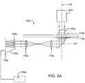
- wavefront sensor 100 for analyzing calibration of a laser ablation system using a Hartmann-Shack wavefront sensor is schematically illustrated according to an embodiment of the present invention.
- wavefront sensor 100 may either be incorporated into a laser ablation system such as the one described above, may be coupled with such a laser ablation system, or may comprise a stand-alone calibration system.
- wavefront sensor 100 may be used merely to analyze calibration, while in other embodiments analyzer 100 may also be used to calibrate a laser ablation system.
- analyzer 100 calibrates a laser ablation system automatically.
- wavefront sensor 100 may be positioned so as to analyze calibration of a laser ablation system in a treatment plane.
- wavefront sensor 100 may be either wholly or partially positioned in the treatment plane and may be fixedly or movably positioned in the treatment plane. In some embodiments, all or part of wavefront sensor 100 may be coupled with a moveable member, such as a movable arm, linear sliding track or the like to provide movable positioning in the treatment plane.
- a moveable member such as a movable arm, linear sliding track or the like to provide movable positioning in the treatment plane.
- wavefront sensor 100 includes a light source 102, a selectively laser ablatable test surface 110, a light detection assembly 105, and a processor 108.
- light detection assembly 105 comprises a lenslet array 104 and a light sensor device 106, while in other embodiments light detection assembly 105 comprises alternative and/or additional components.
- light detection assembly comprises a wavefront sensor, such as a Hartmann-Shack sensor, a Tscherning sensor, a ray tracing sensor, a shearing interferometer sensor, an amplitude grating sensor, or a pattern distortion measuring apparatus.
- Other embodiments, however, may include any other suitable light detection assemblies.
- wavefront sensor 100 may also include one or more filters 112, such as a bandpass filter, adjustment lenses 114, 116, one or more reflective surfaces such as mirrors (not shown), additional optical components (not shown), and/or any other suitable components positioned at suitable locations along the device.
- filters 112 such as a bandpass filter
- adjustment lenses 114, 116 such as adjustment lenses 114, 116
- one or more reflective surfaces such as mirrors (not shown)
- additional optical components not shown
- any other suitable components positioned at suitable locations along the device.
- Light source 102 which may be powered via an internal or external power supply (not shown), generally provides light 120 directed through test surface 110.
- light 120 may pass through a reference structure or other component(s) before passing through test surface 110, but such a reference structure is not required.
- Light rays 120 then pass through any additional, optional optics, such as bandpass filter 112 and lenses 114, 116, before passing through to light detection assembly 105.
- Optional adjustment lenses 114, 116 may be used to focus light 120 on lens array 104, adjust the width of the light pattern, and/or the like.
- light source 102 may be offset relative to one or more other components of wavefront sensor 100, and one or more mirrors or other reflective surfaces may be used to direct light 120 in a desired path.
- wavefront sensor 100 is shown as comprising generally a straight line in Fig. 2 , any suitable configuration is contemplated within the scope of the invention.
- Wavefront technology is one way that laser ablation eye surgical systems may track and measure optical characteristics of a patient's eye.
- Wavefront measurement of the eye typically creates a high order aberration map that permits assessment of aberrations throughout the optical pathway of the eye, for example both internal aberrations and aberrations on the corneal surface.
- the aberration information can then be used to compute a custom ablation pattern for allowing a surgical laser system to correct the complex aberrations in and on the patient's eye.
- wavefront technology is used to measure optical characteristics of test surface 110, rather than of a patient's eye.
- One exemplary wavefront technology system is the VISX WaveScan ® system, which uses Hartmann-Shack wavefront sensors that can quantify aberrations throughout the entire optical system of the patient's eye, including sphero-cylindrical errors, coma, and a host of other high-order aberrations.
- the aberrations in and on the patient's eye can be displayed to the surgeon in the form of an aberration map.
- devices and methods of the present invention involve passing light through test surface 110 and then through light detection assembly 105, one embodiment of which is a Hartmann-Shack wavefront sensor.
- Light sensor device 106 generally transforms light 120 that contacts it into electrical signals.
- light sensor device 106 may comprise any suitable device for converting or transforming light 120 into electrical signals.
- light sensor device 106 may comprise a charge-coupled device (CCD), which converts the light 120 that contacts it into digital image signals, so that the image information can be analyzed by processor 108.
- CCD charge-coupled device
- Processor 108 typically comprises hardware, software, and/or firmware arranged to calculate one or more optical characteristics of the image of light that contacts light sensor device 106. Processor 108 will often determine optical quality, optionally by measuring the smallest features or spatial frequencies which are accurately reproduced in the image that contacts the light sensor device 106. Processor 108 may also determine refractive power and/or shape of test surface 110. More complex analysis may also be provided. Processor 108 may be described as being an optical transfer function calculation device, a modulation transfer function calculation device, or the like, depending on which quality measurement is used within the system.
- Processor 108 may comprise any of a number of various components, such as an image grabber, a switch, a computer, a display, and/or any other suitable components or combinations.
- processor 108 generates data such as but not limited to ablation depths along the surface of test surface 110, ablation shapes, presence of aberrations such as high order aberrations, presence of artifacts, powers of test surfaces, overall shapes of test surfaces (cylindrical, spherical, etc.), heights or depths of surface aberrations or artifacts, and/or the like.
- data may be provided by processor 108 in any suitable form, such as in the form of a two-dimensional surface map, a three-dimensional surface map, a chart, a table, a graph and/or any other readout on a digital display.
- Test surface 110 may show, for example, ablation patterns, shapes and depths of high-order aberrations, artifact shapes and depths, locations of aberrations and artifacts, and/or the like.
- data may be input directly into a calibration system of a laser ablation system to enable a calibration based on the data derived from processor 108.
- processor 108 may be used to perform any processing function of electrical signals from light sensor device 106 into data.
- a wavefront sensor 100a includes components similar to those described above, including a light source 102a for providing light 120a, a test surface 110a, a bandpass filter 112a, lenses 114a and 116a, a light detection assembly 105a including a lenslet array 104a and a light sensor device 106a, and a processor 108a.
- This embodiment also includes one or more mirrors 111 to reflect light 120a.
- test surface 110a is positioned in a treatment plane 130.
- a "treatment plane" is defined as any plane to which a laser may be directed from a laser system to perform an ablation procedure.
- test surface 110a is directed along treatment plane 130 to pass through test surface 110a, which is located along treatment plane 130, and subsequently to pass through the other components of wavefront sensor 100a.
- light may be passed to a treatment plane, but not along the plane, to pass through the test surface.
- disposing test surface 110a in treatment plane 130 may provide a number of advantages in preparing and performing a laser ablation procedure.
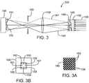
- a wavefront sensor may comprise a shearing interferometer device 200.
- Shearing interferometer 200 suitably includes a half-wave phase plate array 146, an imaging lens 149 and an aperture stop 150 arranged between test surface 110 and light sensor device 106.
- phase plate array 146 is positioned relatively close to test surface 110 so that an aberrated wavefront 145 created by light 120 passing through test surface 110 has little distance to propagate before it is intercepted by phase plate array 146.
- phase plate array 146 may comprise a checkerboard pattern of elements, with uncolored square elements 153 optically thicker than colored square elements 154 by one-half a wavelength of light 120 provided by light source (not shown).
- Phase array 146 thus acts as a diffraction grating, dividing the aberrated wavefront 145 into odd diffraction orders but creating no even orders, or zero order.
- the +1 and -1 orders so created are shown as light beams 147 (dashed lines) and 148 (solid lines). These beams 147, 148, each carrying aberration information, intersect and are focused by lens 149.
- Aperture 150 is positioned in the focal plane of lens 149, where beams 147, 148 come to focus. In this plane each order becomes a focused spot, displaced from the other orders by virtue of the fact that each order passes into lens 149 at a different angle in a specific direction of diffraction.
- aperture 150 has clear areas at the locations of the first order diffraction spots but is otherwise opaque. Hence only the first order beams, shown by the diffraction focal points 155, 156, 157 ,158, 159, 160, 161 and 162, pass through the aperture. These spots represent the x +1 and -1 orders, the y +1 and -1 orders, and the x,y mixed first orders. All other orders are blocked.
- the first order beams 147, 148 pass on to light sensor device 106, typically a charge coupled image sensor, which lies in the plane where lens 149 creates images in each diffracted beam of aberrated wavefront 145.
- These images, 151 and 152, are displaced or sheared with respect to one another and they interfere to produce a fringe pattern known as a shearing interferogram.
- the gradient or slope information of the original wavefront may be obtained via image processing, thus providing information analogous to that obtained from a Hartmann-Shack wavefront sensor.
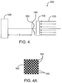
- wavefront gradient measurement may be provided via a grating analyzer 300.
- Grating analyzer 300 generally includes a crossed grid sinusoidal amplitude grating 163 located at distance T from light sensor device 106, typically a charge coupled array. As aberrrated wavefront 145 passes through grating 163, diffraction takes place in the Talbot plane, located at distance T from grating 163 and in the plane of light sensor device 106, a diffraction pattern is formed. The Fourier transform of this diffraction pattern is taken and from it the wavefront gradient information may be extracted.
- Figure 4A shows a frontal view of crossed grid sinusoidal amplitude grating 163. At the center of clear squares 164, the transmission fraction of the grating is 1.0. This transmission amplitude decreases in a sinusoidal fashion until at the center of gray squares 165 the transmission fraction of the grating is 0.0.
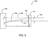
- yet another embodiment of a wavefront sensor may include a ray tracing sensor device 400 capable of measuring a wavefront gradient.
- the wide collimated light beam 120 of the Hartmann-Shack sensor is replaced with a thin beam of light 166 that may be sequentially moved parallel to itself so that it sequentially samples ablated test surface 110 at different, known locations x.
- beam 166 is deflected to a path 167 and strikes light sensor device 106, located at distance D from test surface 110. If beam 166 had not been deflected, it would have followed an alternate path 168 and intersected sensor device 106 a distance d from the position that the actual path 167 strikes the sensor.
- the value d is measured by light sensor device 106.
- the ratio d/D is the tangent of the deflection angle 169. This ratio is the slope of aberrated wavefront 145 at location x. From a series of such measurements at different x locations over the surface of the ablated test surface, the wavefront may be reconstructed.
- any number of beams passed through test object 110 at a number of known locations may be used to measure the gradient at multiple locations simultaneously.
- a wavefront sensor of the present invention may include a pattern distortion measuring apparatus 500 to provide wavefront gradient measurement.
- Apparatus 500 uses a light source 170 that provides a luminous pattern, typically but not necessarily an alternating pattern of dark and luminous stripes.
- Light source 170 is located a known distance A from test surface 110.
- Light from light source 170 passes through test surface 110 to a lens 171 located at distance B from surface 110.
- Lens 171 has a small aperture created by a stop 172 so that it acts somewhat like a pinhole camera.
- An image 173 of light from light source 170 is formed by lens 171 on light sensor device 106. Image 173 is distorted by the presence of ablated test object 110.
- the location, xt, on test surface 110 of deflected ray 175b can be found using the geometric principal of similar triangles. Then knowledge of distances A, xt and xs allow the initial direction of travel of ray 175a to be found. Knowledge of distances C and xd allow the final direction of deflected ray 175b after deflection by test surface 110 to be found. The difference between these two ray directions give ray deflection angle 177 caused by ablated test object 110 at location xt to be found. This deflection is the gradient of aberrated wavefront 145 at location xt.
- one form of data which may be generated by wavefront sensor 100 is one or more surface maps.
- Surface maps may include, for example, two-dimensional maps 180a, 180b and/or three-dimensional maps 190a, 190b.
- Surface maps may be helpful in assessing the surface contour or overall shape of test surface 110 and may also be used to derive magnitudes of high-order aberrations and/or artifacts.
- high-order aberrations and/or artifacts may be represented by peaks 192a, 192b in three-dimensional maps and/or darker regions 182a, 182b (or lighter regions) on two-dimensional maps.
- processor 108 may provide measurements of high-order aberrations and/or artifacts by height, diameter, and/or other dimensions, so that such information can be used for calibration.
- processor 108 provides surface maps by converting data from light sensor device 106 using a reconstruction algorithm, such as Fourier or Zernike reconstruction algorithms. Any other suitable process used by processor 108 to convert data into a usable form is contemplated, however.
- wavefront sensor 100 in addition to providing data regarding high-order aberrations and/or artifacts, wavefront sensor 100 also provides data regarding refractive power of an ablation. Wavefront sensors 100 may further be used to measure wavefront gradients in lenses that have shapes more complex than sphero-cylindrical, such measurements not being possible with current, conventional lensometers.
Landscapes
- Health & Medical Sciences (AREA)
- Life Sciences & Earth Sciences (AREA)
- Physics & Mathematics (AREA)
- Ophthalmology & Optometry (AREA)
- General Health & Medical Sciences (AREA)
- Public Health (AREA)
- Veterinary Medicine (AREA)
- Surgery (AREA)
- Engineering & Computer Science (AREA)
- Biomedical Technology (AREA)
- Heart & Thoracic Surgery (AREA)
- Animal Behavior & Ethology (AREA)
- Spectroscopy & Molecular Physics (AREA)
- Vascular Medicine (AREA)
- Nuclear Medicine, Radiotherapy & Molecular Imaging (AREA)
- General Physics & Mathematics (AREA)
- Optics & Photonics (AREA)
- Biophysics (AREA)
- Medical Informatics (AREA)
- Molecular Biology (AREA)
- Laser Surgery Devices (AREA)
- Eye Examination Apparatus (AREA)
- Lasers (AREA)
- Length Measuring Devices By Optical Means (AREA)
- Laser Beam Processing (AREA)
Claims (44)
- Verfahren zur Analyse der Kalibration eines Laserablationssystems zur Durchführung eines Ablationsverfahrens an einem Auge, wobei das Verfahren das Folgende umfasst:selektives Ablatieren einer Testoberfläche (110) mit dem Lasersystem;Leiten von Licht von einer Lichtquelle (102) durch die Testoberfläche; undAnalysieren des Lichts, nachdem das Licht durch die Testoberfläche (110) geleitet wurde, unter Verwendung wenigstens eines Wellenfrontsensors (100) zur Bestimmung einer Brechkraft der Testoberfläche und wenigstens einer zusätzlichen Ablationseigenschaft des Laserablationssystems, wobei die Analyse die Messung von Wellenfrontdaten, die unter Verwendung des Lichts erzeugt wurden, umfasst, und die Verwendung eines Rekonstruktionsalgorithmus zur Erzeugung einer Oberflächenkarte der Testoberfläche (110).
- Verfahren nach Anspruch 1, wobei die Testoberfläche (110) entlang einer Behandlungsebene (130) angeordnet ist, wobei die Behandlungsebene eine Ebene umfasst, auf die ein Laser von dem Lasersystem zur Durchführung des Ablationsverfahrens gerichtet wird, und wobei das Licht von der Lichtquelle durch die Testoberfläche zur Behandlungsebene gerichtet wird.
- Verfahren nach Anspruch 2, wobei das Licht mit wenigstens einer Kalibriervorrichtung analysiert wird.
- Verfahren nach Anspruch 2, wobei die Testoberfläche (110) während der Ablation, dem Leiten und der Analyse fest in der Behandlungsebene (130) angeordnet ist.
- Verfahren nach Anspruch 4, ferner umfassend das Bewegen der Testoberfläche (110) in die Behandlungsebene (130) vor dem Ablationsschritt.
- Verfahren nach Anspruch 5, wobei das Bewegen der Testoberfläche (110) das Bewegen einer Plattform, mit der die Testoberfläche (110) verbunden ist, umfasst.
- Verfahren nach Anspruch 1, wobei die Testoberfläche in eine Linse ablatiert wird.
- Verfahren nach Anspruch 1, wobei die Testoberfläche (110) ein Kalibrierelement aus Kunststoff umfasst.
- Verfahren nach Anspruch 1, wobei die selektive Ablation das Aufbringen von Laserenergie auf die Testoberfläche (110) zur Annäherung an wenigstens ein Verfahren umfasst, das aus der aus Astigmatie-Korrektur eines menschlichen Auges, Myopie-Korrektur eines menschlichen Auges, Hyperopie-Korrektur eines menschlichen Auges und phototherapeutischer Abflachung bestehenden Gruppe ausgewählt ist.
- Verfahren nach Anspruch 1, wobei der Wellenfrontsensor (100) aus der aus einem Hartmann-Shack-Sensor, einem Tscherning-Sensor, einem Strahlverfolgungssensor, einem Scher-Interferometer-Sensor, einem Amplitudengittersensor und einer Vorrichtung zur Messung von Musterverzerrung bestehenden Gruppe ausgewählt ist.
- Verfahren nach Anspruch 1, wobei die Analyse die Bestimmung wenigstens einer Qualität und/oder einer Form der ablatierten Testoberfläche (110) umfasst.
- Verfahren nach Anspruch 11, wobei die Analyse der Qualität der ablatierten Testoberfläche (110) den Nachweis wenigstens einer Aberration höherer Ordnung oder eines Artefakts auf der Testoberfläche umfasst.
- Verfahren nach Anspruch 12, wobei die Analyse der Qualität ferner die Bestimmung einer Höhe der wenigstens einen Aberration höherer Ordnung oder des Artefakts auf der Testoberfläche (110) umfasst.
- Verfahren nach Anspruch 12, ferner umfassend die Erstellung wenigstens einer Karte der Testoberfläche (110), wobei die Karte eine Lokalisation der wenigstens einen Aberration höherer Ordnung oder des Artefakts auf der Testoberfläche zeigt.
- Verfahren nach Anspruch 14, wobei die Karte ferner Formen der wenigstens einen Aberration höherer Ordnung oder des Artefakts auf der Testoberfläche (110) zeigt.
- Verfahren nach Anspruch 1, wobei die Analyse das Folgende umfasst:Umwandlung des Lichts in elektrische Signale; undAufbereitung der elektrischen Signale zur Bestimmung der Brechkraft und der wenigstens einen zusätzlichen Ablationseigenschaft.
- Verfahren nach Anspruch 16, wobei die Umwandlung des Lichts das Folgende umfasst:Durchleiten des Lichts durch eine Wellenfront-Linsenanordnung (104); undErfassen des durchgeleiteten Lichts mit einer Lichtdetektionsvorrichtung (105).
- Verfahren nach Anspruch 17, wobei die Lichtdetektionsvorrichtung (105) ein ladungsgekoppeltes Bauelement umfasst.
- Verfahren nach Anspruch 17, ferner umfassend die Anpassung wenigstens einer Fokussierlinse, die in einem Pfad zwischen der Testoberfläche und der Linsenanordnung angeordnet ist, zur Anpassung des Lichts vor dessen Durchleitung durch die Linsenanordnung.
- Verfahren nach Anspruch 16, ferner umfassend die Verwendung von elektrischen Signalen zur Erzeugung eines Bilds, das ungefähr die Testoberfläche darstellt.
- Verfahren nach Anspruch 1, wobei die Verwendung des Rekonstruktionsalgorithmus die Verwendung eines Zernike-Rekonstruktionsalgorithmus oder eines Fourier-Rekonstruktionsalgorithmus umfasst.
- Verfahren nach Anspruch 1, ferner umfassend die Anpassung des Laserablationssystems auf Basis der Brechkraft und der wenigstens einen zusätzlichen Ablationseigenschaft, die während des Analyseschritts bestimmt wurde.
- Verfahren nach Anspruch 22, wobei die wenigstens eine Ablationseigenschaft wenigstens eine Qualität und/oder eine Form der ablatierten Testoberfläche (110) umfasst.
- Kalibriervorrichtung zur Verwendung mit einem Laserablationssystems, wobei das Laserablationssystem eine Oberfläche durch selektive Laserablation der Oberfläche umformen kann, wobei die Kalibriervorrichtung das Folgende umfasst:eine selektiv ablatierbare Testoberfläche (110);eine Lichtdetektionsanordnung (105), die einen Wellenfrontsensor (100) umfasst;eine Lichtquelle (102) zum Durchleiten von Licht durch die ablatierte Testoberfläche (110) zur Lichtdetektionsanordnung; undeinen Prozessor (22), der mit der Lichtdetektionsanordnung verbunden ist, um das nachgewiesene Licht zu analysieren und eine Brechkraft der Testoberfläche (110) und wenigstens eine zusätzliche Ablationseigenschaft des Laserablationssystems zu bestimmen, wobei die Vorrichtung ausgelegt ist, Wellenfrontdaten zu messen, die unter Verwendung der Lichtquelle (102) erzeugt wurden, und wobei der Prozessor ausgelegt ist, einen Rekonstruktionsalgorithmus zur Erstellung einer Oberflächenkarte der Testoberfläche (110) zu verwenden.
- Kalibriervorrichtung nach Anspruch 24, wobei die Testoberfläche (110) entlang einer Behandlungsebene (130) positionierbar ist, wobei die Behandlungsebene eine Ebene umfasst, auf die ein Laser von dem Lasersystem zur Durchführung eines Umformungsverfahrens gerichtet wird, und wobei die Lichtquelle (102) angeordnet ist, Licht zur Behandlungsebene, durch die ablatierte Testoberfläche zur Lichtdetektionsanordnung zu leiten.
- Kalibriervorrichtung nach Anspruch 25, wobei die Testoberfläche (110) fest entlang der Behandlungsebene (130) angeordnet ist, während die Testoberfläche ablatiert wird und Licht durch die Testoberfläche von der Lichtquelle geleitet wird.
- Kalibriervorrichtung nach Anspruch 26, ferner umfassend eine bewegliche Positioniervorrichtung, mit der die Testoberfläche (110) verbunden ist, wobei die Positioniervorrichtung zur Positionierung der Testoberfläche entlang der Behandlungsebene beweglich ist.
- Kalibriervorrichtung nach Anspruch 27, wobei die wenigstens eine Positioniervorrichtung aus der aus einer beweglichen Plattform, einem Gelenkarm, einem Dreharm, einem linearen Schlitten und einem Rahmenschwenkteil bestehenden Gruppe ausgewählt ist.
- Kalibriervorrichtung nach Anspruch 24, wobei die ablatierbare Testoberfläche (110) eine Linse umfasst.
- Kalibriervorrichtung nach Anspruch 24, wobei die ablatierbare Testoberfläche (110) ein Kalibrierelement aus Kunststoff umfasst.
- Kalibriervorrichtung nach Anspruch 24, wobei der Prozessor Hardware, Software und/oder Firmware zur Anwendung wenigstens eines Zernike-Rekonstruktionsalgorithmus und/oder eines Fourier-Rekonstruktionsalgorithmus zur Erstellung der Oberflächenkarte der Testoberfläche umfasst.
- Kalibriervorrichtung nach Anspruch 24, wobei der Wellenfrontsensor (100) aus der aus einem Hartmann-Shack-Sensor, einem Tscherning-Sensor, einem Strahlverfolgungssensor, einem Scher-Interferometer-Sensor, einem Amplitudengittersensor und einer Vorrichtung zur Messung von Musterverzerrung bestehenden Gruppe ausgewählt ist.
- Kalibriervorrichtung nach Anspruch 24, wobei die Lichtdetektionsvorrichtung (105) ein ladungsgekoppeltes Bauelement zur Umwandlung von Licht in elektrische Signale umfasst.
- Kalibriervorrichtung nach Anspruch 33, wobei der Prozessor (22) dem ladungsgekoppelten Bauelement verbunden ist, um die elektrischen Signale auszuwerten und die Brechkraft und die wenigstens eine zusätzliche Ablationseigenschaft zu bestimmen.
- Kalibriervorrichtung nach Anspruch 34, wobei der Prozessor (22) ferner mit dem Laserablationssystem verbunden ist, um das Laserablationssystem auf Basis der Analyse der elektrischen Signale zu kalibrieren.
- Kalibriervorrichtung nach Anspruch 24, wobei der Prozessor (22) Mittel zum Anlegen wenigstens eines Zernike-Rekonstruktionsalgorithmus und/oder eines Fourier-Rekonstruktionsalgorithmus zur Ableitung wenigstens einer Oberflächenkarte der Testoberfläche aus den von der Lichtdetektionsanordnung gemessenen Wellenfrontdaten umfasst.
- Kalibriervorrichtung nach Anspruch 24, ferner umfassend wenigstens eine Einstellungslinse (114, 116), die zwischen der Lichtquelle (102) und der Lichtdetektionsanordnung (105) angeordnet ist, zur Einstellung wenigstens einer Eigenschaft des Lichts.
- Kalibriervorrichtung nach Anspruch 24, wobei die wenigstens eine zusätzliche Ablationseigenschaft wenigstens eine Qualität und/oder eine Form der ablatierten Testoberfläche (110) umfasst.
- Kalibriervorrichtung nach Anspruch 38, wobei die Qualität wenigstens eine Aberration höherer Ordnung oder einen Artefakt auf der Testoberfläche (110) umfasst.
- Kalibriervorrichtung nach Anspruch 39, wobei der Prozessor (22) angeordnet ist, wenigstens ein Bild der ablatierten Testoberfläche (110) zu erzeugen, wobei das wenigstens eine Bild die wenigstens eine Aberration höherer Ordnung oder den Artefakt zeigt.
- Kalibriervorrichtung nach Anspruch 40, wobei das wenigstens eine Bild wenigstens eine Oberflächenkarte der Testoberfläche (110) umfasst.
- Kalibriervorrichtung nach Anspruch 39, wobei der Prozessor (22) angeordnet ist, wenigstens eine Messung der wenigstens einen Aberration höherer Ordnung oder des Artefakts zu erzeugen.
- Kalibriervorrichtung nach Anspruch 24, wobei der Prozessor (22) mit dem Laserablationssystem verbunden ist.
- Kalibriervorrichtung nach Anspruch 43, wobei der Prozessor (22) angeordnet ist, das Lasersystem automatisch zu kalibrieren, wenigstens auf Basis der Brechkraft und der wenigstens einen zusätzlichen Ablationseigenschaft.
Applications Claiming Priority (3)
| Application Number | Priority Date | Filing Date | Title |
|---|---|---|---|
| US46173903P | 2003-04-09 | 2003-04-09 | |
| US51886703P | 2003-11-10 | 2003-11-10 | |
| PCT/US2004/007780 WO2004093663A2 (en) | 2003-04-09 | 2004-03-12 | Wavefront calibration analyzer and methods |
Publications (3)
| Publication Number | Publication Date |
|---|---|
| EP1617751A2 EP1617751A2 (de) | 2006-01-25 |
| EP1617751A4 EP1617751A4 (de) | 2009-12-16 |
| EP1617751B1 true EP1617751B1 (de) | 2016-05-04 |
Family
ID=33313414
Family Applications (1)
| Application Number | Title | Priority Date | Filing Date |
|---|---|---|---|
| EP04720461.5A Expired - Lifetime EP1617751B1 (de) | 2003-04-09 | 2004-03-12 | Wellenfront-kalibrationsanalysator und verfahren |
Country Status (6)
| Country | Link |
|---|---|
| US (1) | US7355695B2 (de) |
| EP (1) | EP1617751B1 (de) |
| JP (1) | JP4769711B2 (de) |
| CA (1) | CA2521845C (de) |
| MX (1) | MXPA05010791A (de) |
| WO (1) | WO2004093663A2 (de) |
Cited By (1)
| Publication number | Priority date | Publication date | Assignee | Title |
|---|---|---|---|---|
| CN105606211A (zh) * | 2015-09-11 | 2016-05-25 | 北京理工大学 | 用于相关哈特曼-夏克波前传感器的在轨零位标定方法 |
Families Citing this family (37)
| Publication number | Priority date | Publication date | Assignee | Title |
|---|---|---|---|---|
| US7556378B1 (en) | 2003-04-10 | 2009-07-07 | Tsontcho Ianchulev | Intraoperative estimation of intraocular lens power |
| US7425067B2 (en) * | 2003-11-14 | 2008-09-16 | Ophthonix, Inc. | Ophthalmic diagnostic instrument |
| US7547102B2 (en) * | 2004-03-03 | 2009-06-16 | Amo Manufacturing Usa, Llc | Wavefront propagation from one plane to another |
| US7296893B2 (en) * | 2004-03-03 | 2007-11-20 | Visx, Incorporated | Transformation methods of wavefront maps from one vertex distance to another |
| ES2665536T3 (es) | 2004-04-20 | 2018-04-26 | Alcon Research, Ltd. | Microscopio quirúrgico y sensor de frente de onda integrados |
| JP4609838B2 (ja) * | 2004-08-10 | 2011-01-12 | 株式会社ニデック | 角膜手術装置 |
| WO2007035334A2 (en) * | 2005-09-19 | 2007-03-29 | Advanced Vision Engineering, Inc. | Methods and apparatus for comprehensive vision diagnosis |
| US20080058778A1 (en) * | 2006-08-31 | 2008-03-06 | Liedel Kevin K | Performance assessment system for refractive lasers and associated methods |
| US7715952B2 (en) * | 2007-09-20 | 2010-05-11 | Tokyo Electron Limited | Temperature setting of thermal processing plate using zernike coefficients |
| US8333474B2 (en) | 2007-10-19 | 2012-12-18 | Wavetec Vision Systems, Inc. | Optical instrument alignment system |
| US7594729B2 (en) | 2007-10-31 | 2009-09-29 | Wf Systems, Llc | Wavefront sensor |
| EP2249718B1 (de) | 2008-01-14 | 2019-09-18 | Conventus Orthopaedics, Inc. | Gerät zur reparatur von frakturen |
| US8020994B2 (en) * | 2008-09-04 | 2011-09-20 | Heidelberg Engineering Gmbh | Custom phase plate |
| US8550624B2 (en) | 2008-11-06 | 2013-10-08 | Wavetec Vision Systems, Inc. | Optical angular measurement system for ophthalmic applications and method for positioning of a toric intraocular lens with increased accuracy |
| WO2010100644A1 (en) * | 2009-03-04 | 2010-09-10 | Elie Meimoun | Wavefront analysis inspection apparatus and method |
| US8876290B2 (en) | 2009-07-06 | 2014-11-04 | Wavetec Vision Systems, Inc. | Objective quality metric for ocular wavefront measurements |
| CN104367299B (zh) | 2009-07-14 | 2017-09-15 | 波技术视觉系统公司 | 眼科手术测量系统 |
| EP2453822B1 (de) | 2009-07-14 | 2014-08-20 | WaveTec Vision Systems, Inc. | Bestimmung der tatsächlichen linsenposition einer intraokularen linse mithilfe aphaker brechkraft |
| CN101639382B (zh) * | 2009-08-25 | 2010-09-29 | 中国科学院光电技术研究所 | 一种使用球面波前绝对标定哈特曼-夏克传感器的方法 |
| CN101718590B (zh) * | 2009-11-27 | 2011-02-09 | 中国科学院光电技术研究所 | 基于远场性能指标的自适应光学系统标定装置 |
| KR20140006956A (ko) * | 2011-02-15 | 2014-01-16 | 웨이브라이트 게엠베하 | 물체의 광학 특성을 측정하기 위한 장치 |
| US20130063699A1 (en) * | 2011-09-09 | 2013-03-14 | Welch Allyn, Inc. | Ocular Error Detection |
| US9182289B2 (en) * | 2011-10-14 | 2015-11-10 | Canon Kabushiki Kaisha | Apparatus and method for estimating wavefront parameters |
| CN104010602B (zh) * | 2011-12-13 | 2016-04-20 | 视乐有限公司 | 用于校准激光装置的测试装置 |
| US9072462B2 (en) | 2012-09-27 | 2015-07-07 | Wavetec Vision Systems, Inc. | Geometric optical power measurement device |
| WO2015081214A1 (en) | 2013-11-26 | 2015-06-04 | Abbott Medical Optics Inc. | System and method for measuring dysphotopsia |
| US9572715B2 (en) * | 2014-07-25 | 2017-02-21 | Amo Manufacturing Usa, Llc | Systems, devices, and methods for calibration of beam profilers |
| CN106152947B (zh) * | 2015-03-31 | 2019-11-29 | 北京京东尚科信息技术有限公司 | 测量物体尺寸的设备、方法和装置 |
| DE102015015095A1 (de) * | 2015-11-20 | 2017-05-24 | Novartis Ag | Verfahren zum Testen einer Lasereinrichtung |
| ES2808701T3 (es) * | 2016-05-02 | 2021-03-01 | Alcon Inc | Procesamiento y presentación de imágenes de cono de acoplamiento de cirugía oftálmica con láser de femtosegundo |
| EP3522771B1 (de) | 2016-10-25 | 2022-04-06 | Amo Groningen B.V. | Realistische augenmodelle zur konstruktion und bewertung von intraokularlinsen für ein grosses sichtfeld |
| US10739227B2 (en) | 2017-03-23 | 2020-08-11 | Johnson & Johnson Surgical Vision, Inc. | Methods and systems for measuring image quality |
| AU2018376564B2 (en) | 2017-11-30 | 2024-11-14 | Amo Groningen B.V. | Intraocular lenses that improve post-surgical spectacle independent and methods of manufacturing thereof |
| CN109029719B (zh) * | 2018-06-25 | 2020-12-25 | 南京理工大学 | 基于夏克哈特曼法的紫外光能分布探测系统及其探测方法 |
| JP7367177B2 (ja) | 2019-08-05 | 2023-10-23 | ジャイラス エーシーエムアイ インク ディー/ビー/エー オリンパス サージカル テクノロジーズ アメリカ | 照射制御を伴うレーザシステム |
| WO2022233683A1 (en) | 2021-05-05 | 2022-11-10 | Amo Groningen B.V. | Ring halometer system and method for quantifying dysphotopsias |
| CN114964181B (zh) * | 2022-05-27 | 2023-04-25 | 哈尔滨工业大学 | 基于波前零差干涉的高精度双轴激光水平仪及测量方法 |
Family Cites Families (46)
| Publication number | Priority date | Publication date | Assignee | Title |
|---|---|---|---|---|
| US2003A (en) * | 1841-03-12 | Improvement in horizontal windivhlls | ||
| US2001A (en) * | 1841-03-12 | Sawmill | ||
| US2002A (en) * | 1841-03-12 | Tor and planter for plowing | ||
| US4669466A (en) | 1985-01-16 | 1987-06-02 | Lri L.P. | Method and apparatus for analysis and correction of abnormal refractive errors of the eye |
| US6296634B1 (en) | 1991-03-08 | 2001-10-02 | Visx, Incorporated | Ophthalmological surgery technique with active patient data card |
| CA2073802C (en) | 1991-08-16 | 2003-04-01 | John Shimmick | Method and apparatus for combined cylindrical and spherical eye corrections |
| DE4232915A1 (de) | 1992-10-01 | 1994-04-07 | Hohla Kristian | Vorrichtung zur Formung der Cornea durch Abtragen von Gewebe |
| US5460627A (en) | 1993-05-03 | 1995-10-24 | O'donnell, Jr.; Francis E. | Method of evaluating a laser used in ophthalmological surgery |
| US20020026181A1 (en) * | 1993-05-03 | 2002-02-28 | O'donnell Francis E. | Method of evaluating surgical laser |
| US5772656A (en) * | 1993-06-04 | 1998-06-30 | Summit Technology, Inc. | Calibration apparatus for laser ablative systems |
| US5610707A (en) | 1995-07-07 | 1997-03-11 | Lockheed Missiles & Space Co., Inc. | Wavefront sensor for a staring imager |
| US20010041884A1 (en) | 1996-11-25 | 2001-11-15 | Frey Rudolph W. | Method for determining and correcting vision |
| AU1386899A (en) | 1997-11-06 | 1999-05-31 | Visx Incorporated | Systems and methods for calibrating laser ablations |
| US6626924B1 (en) | 1998-06-01 | 2003-09-30 | Peter J. Klopotek | Surgical microtomes |
| US6409345B1 (en) * | 2000-08-08 | 2002-06-25 | Tracey Technologies, Llc | Method and device for synchronous mapping of the total refraction non-homogeneity of the eye and its refractive components |
| US6166737A (en) * | 1998-12-04 | 2000-12-26 | Compal Electronics, Inc. | Quick input device for window selection list control signal of notebook-type computer |
| WO2000041639A1 (en) * | 1999-01-13 | 2000-07-20 | Lasersight Technologies, Inc. | Profiling calibration plate |
| US6245059B1 (en) | 1999-04-07 | 2001-06-12 | Visx, Incorporated | Offset ablation profiles for treatment of irregular astigmation |
| US6050687A (en) | 1999-06-11 | 2000-04-18 | 20/10 Perfect Vision Optische Geraete Gmbh | Method and apparatus for measurement of the refractive properties of the human eye |
| US6184974B1 (en) | 1999-07-01 | 2001-02-06 | Wavefront Sciences, Inc. | Apparatus and method for evaluating a target larger than a measuring aperture of a sensor |
| US6666855B2 (en) | 1999-09-14 | 2003-12-23 | Visx, Inc. | Methods and systems for laser calibration and eye tracker camera alignment |
| US6559934B1 (en) | 1999-09-14 | 2003-05-06 | Visx, Incorporated | Method and apparatus for determining characteristics of a laser beam spot |
| US6086204A (en) | 1999-09-20 | 2000-07-11 | Magnante; Peter C. | Methods and devices to design and fabricate surfaces on contact lenses and on corneal tissue that correct the eye's optical aberrations |
| US6419671B1 (en) | 1999-12-23 | 2002-07-16 | Visx, Incorporated | Optical feedback system for vision correction |
| US6234631B1 (en) | 2000-03-09 | 2001-05-22 | Lasersight Technologies, Inc. | Combination advanced corneal topography/wave front aberration measurement |
| US6673062B2 (en) * | 2000-03-14 | 2004-01-06 | Visx, Inc. | Generating scanning spot locations for laser eye surgery |
| US6659613B2 (en) | 2000-03-27 | 2003-12-09 | Board Of Regents, The University Of Texas System | Methods and systems for measuring local scattering and aberration properties of optical media |
| WO2001078585A2 (en) | 2000-04-19 | 2001-10-25 | Alcon Universal Ltd. | Wavefront sensor for objective measurement of an optical system and associated methods |
| US6338559B1 (en) | 2000-04-28 | 2002-01-15 | University Of Rochester | Apparatus and method for improving vision and retinal imaging |
| US6460997B1 (en) | 2000-05-08 | 2002-10-08 | Alcon Universal Ltd. | Apparatus and method for objective measurements of optical systems using wavefront analysis |
| CA2422855C (en) * | 2000-09-21 | 2012-01-03 | Visx, Inc. | Enhanced wavefront ablation system |
| US6485142B1 (en) | 2000-09-28 | 2002-11-26 | The United States Of America As Represented By The Secretary Of The Navy | Artificial human eye and test apparatus |
| AU2002239515A1 (en) * | 2000-12-08 | 2002-06-18 | Visx Incorporated | Direct wavefront-based corneal ablation treatment program |
| US6626535B2 (en) * | 2000-12-29 | 2003-09-30 | Bausch & Lomb Incorporated | Lens-eye model and method for predicting in-vivo lens performance |
| US6609794B2 (en) | 2001-06-05 | 2003-08-26 | Adaptive Optics Associates, Inc. | Method of treating the human eye with a wavefront sensor-based ophthalmic instrument |
| US6739721B2 (en) | 2001-12-11 | 2004-05-25 | Bausch And Lomb, Inc | Method and apparatus for calibrating and certifying accuracy of a wavefront sensing device |
| US6637884B2 (en) | 2001-12-14 | 2003-10-28 | Bausch & Lomb Incorporated | Aberrometer calibration |
| AU2003216240A1 (en) * | 2002-02-11 | 2003-09-04 | Visx, Inc. | Closed loop system and method for ablating lenses with aberrations |
| CN100450427C (zh) | 2002-02-11 | 2009-01-14 | 维思克斯公司 | 确定相对位置和旋转偏移 |
| US7213919B2 (en) | 2002-02-11 | 2007-05-08 | Visx, Incorporated | Method and device for calibrating an optical wavefront system |
| US6628535B1 (en) * | 2002-03-20 | 2003-09-30 | Formosa Electronic Industries Inc. | Voltage converter with selectable DC output voltage level |
| US7846152B2 (en) * | 2004-03-24 | 2010-12-07 | Amo Manufacturing Usa, Llc. | Calibrating laser beam position and shape using an image capture device |
| MXPA05011131A (es) | 2003-04-18 | 2006-03-10 | Visx Inc | Sistemas y metodos para corregir aberraciones de orden superior en cirugia de refraccion de laser. |
| US7338164B2 (en) | 2003-07-31 | 2008-03-04 | Visx, Incorporated | Systems and methods for eye aberration and image sensor orientation |
| JP5052897B2 (ja) | 2003-11-10 | 2012-10-17 | ヴィズイクス・インコーポレーテッド | 診断用デバイスとレーザー屈折システムとの間のトーショナルアライメントをテストするための方法及び装置 |
| JP2008505696A (ja) | 2004-07-09 | 2008-02-28 | ヴィスクス インコーポレイテッド | 走査レーザー眼手術装置用のレーザーパルス位置モニター |
-
2004
- 2004-03-12 MX MXPA05010791A patent/MXPA05010791A/es active IP Right Grant
- 2004-03-12 US US10/799,439 patent/US7355695B2/en not_active Expired - Fee Related
- 2004-03-12 CA CA2521845A patent/CA2521845C/en not_active Expired - Fee Related
- 2004-03-12 WO PCT/US2004/007780 patent/WO2004093663A2/en not_active Ceased
- 2004-03-12 EP EP04720461.5A patent/EP1617751B1/de not_active Expired - Lifetime
- 2004-03-12 JP JP2006507171A patent/JP4769711B2/ja not_active Expired - Fee Related
Cited By (2)
| Publication number | Priority date | Publication date | Assignee | Title |
|---|---|---|---|---|
| CN105606211A (zh) * | 2015-09-11 | 2016-05-25 | 北京理工大学 | 用于相关哈特曼-夏克波前传感器的在轨零位标定方法 |
| CN105606211B (zh) * | 2015-09-11 | 2017-07-11 | 北京理工大学 | 用于相关哈特曼‑夏克波前传感器的在轨零位标定方法 |
Also Published As
| Publication number | Publication date |
|---|---|
| JP4769711B2 (ja) | 2011-09-07 |
| JP2006522642A (ja) | 2006-10-05 |
| EP1617751A2 (de) | 2006-01-25 |
| EP1617751A4 (de) | 2009-12-16 |
| US20040260275A1 (en) | 2004-12-23 |
| WO2004093663A3 (en) | 2006-01-19 |
| WO2004093663A2 (en) | 2004-11-04 |
| MXPA05010791A (es) | 2005-12-15 |
| US7355695B2 (en) | 2008-04-08 |
| CA2521845C (en) | 2012-05-29 |
| CA2521845A1 (en) | 2004-11-04 |
Similar Documents
| Publication | Publication Date | Title |
|---|---|---|
| EP1617751B1 (de) | Wellenfront-kalibrationsanalysator und verfahren | |
| EP1244393B1 (de) | Optisches feedback-system zur sehkorrektur | |
| EP1999443B1 (de) | Raumfrequenz-wellenfront-sensorsystem und verfahren dafür | |
| US7699470B2 (en) | Systems and methods for prediction of objective visual acuity based on wavefront measurements | |
| CA2475389C (en) | Closed loop system and method for ablating lenses with aberrations | |
| CA2645894C (en) | Shack-hartmann based integrated autorefraction and wavefront measurements of the eye | |
| JP4167064B2 (ja) | 直接の波面に基づいた角膜切除処理プログラム | |
| US6195164B1 (en) | Systems and methods for calibrating laser ablations | |
| US7460288B2 (en) | Methods for determining refractive corrections from wavefront measurements | |
| EP1976470B1 (de) | Auf optischer messung basierende laserleistungskalibrierung | |
| AU2007230815B2 (en) | Shack-hartmann based integrated autorefraction and wavefront measurements of the eye |
Legal Events
| Date | Code | Title | Description |
|---|---|---|---|
| PUAI | Public reference made under article 153(3) epc to a published international application that has entered the european phase |
Free format text: ORIGINAL CODE: 0009012 |
|
| 17P | Request for examination filed |
Effective date: 20051102 |
|
| AK | Designated contracting states |
Kind code of ref document: A2 Designated state(s): AT BE BG CH CY CZ DE DK EE ES FI FR GB GR HU IE IT LI LU MC NL PL PT RO SE SI SK TR |
|
| AX | Request for extension of the european patent |
Extension state: AL LT LV MK |
|
| PUAK | Availability of information related to the publication of the international search report |
Free format text: ORIGINAL CODE: 0009015 |
|
| RIC1 | Information provided on ipc code assigned before grant |
Ipc: G01J 1/00 20060101AFI20060315BHEP Ipc: A61N 5/06 20060101ALI20060315BHEP Ipc: G01B 9/00 20060101ALI20060315BHEP |
|
| DAX | Request for extension of the european patent (deleted) | ||
| RAP1 | Party data changed (applicant data changed or rights of an application transferred) |
Owner name: AMO MANUFACTURING USA, LLC |
|
| A4 | Supplementary search report drawn up and despatched |
Effective date: 20091118 |
|
| RIC1 | Information provided on ipc code assigned before grant |
Ipc: A61F 9/008 20060101ALI20091112BHEP Ipc: G01J 1/00 20060101AFI20060315BHEP Ipc: G01B 9/00 20060101ALI20091112BHEP Ipc: A61N 5/06 20060101ALI20091112BHEP |
|
| RAP1 | Party data changed (applicant data changed or rights of an application transferred) |
Owner name: AMO MANUFACTURING USA, LLC |
|
| 17Q | First examination report despatched |
Effective date: 20110429 |
|
| GRAP | Despatch of communication of intention to grant a patent |
Free format text: ORIGINAL CODE: EPIDOSNIGR1 |
|
| INTG | Intention to grant announced |
Effective date: 20151222 |
|
| GRAS | Grant fee paid |
Free format text: ORIGINAL CODE: EPIDOSNIGR3 |
|
| GRAA | (expected) grant |
Free format text: ORIGINAL CODE: 0009210 |
|
| AK | Designated contracting states |
Kind code of ref document: B1 Designated state(s): AT BE BG CH CY CZ DE DK EE ES FI FR GB GR HU IE IT LI LU MC NL PL PT RO SE SI SK TR |
|
| REG | Reference to a national code |
Ref country code: GB Ref legal event code: FG4D |
|
| REG | Reference to a national code |
Ref country code: CH Ref legal event code: EP |
|
| REG | Reference to a national code |
Ref country code: AT Ref legal event code: REF Ref document number: 797327 Country of ref document: AT Kind code of ref document: T Effective date: 20160515 |
|
| REG | Reference to a national code |
Ref country code: IE Ref legal event code: FG4D |
|
| REG | Reference to a national code |
Ref country code: DE Ref legal event code: R096 Ref document number: 602004049236 Country of ref document: DE |
|
| REG | Reference to a national code |
Ref country code: NL Ref legal event code: MP Effective date: 20160504 |
|
| PG25 | Lapsed in a contracting state [announced via postgrant information from national office to epo] |
Ref country code: NL Free format text: LAPSE BECAUSE OF FAILURE TO SUBMIT A TRANSLATION OF THE DESCRIPTION OR TO PAY THE FEE WITHIN THE PRESCRIBED TIME-LIMIT Effective date: 20160504 Ref country code: FI Free format text: LAPSE BECAUSE OF FAILURE TO SUBMIT A TRANSLATION OF THE DESCRIPTION OR TO PAY THE FEE WITHIN THE PRESCRIBED TIME-LIMIT Effective date: 20160504 |
|
| REG | Reference to a national code |
Ref country code: AT Ref legal event code: MK05 Ref document number: 797327 Country of ref document: AT Kind code of ref document: T Effective date: 20160504 |
|
| PG25 | Lapsed in a contracting state [announced via postgrant information from national office to epo] |
Ref country code: PT Free format text: LAPSE BECAUSE OF FAILURE TO SUBMIT A TRANSLATION OF THE DESCRIPTION OR TO PAY THE FEE WITHIN THE PRESCRIBED TIME-LIMIT Effective date: 20160905 Ref country code: ES Free format text: LAPSE BECAUSE OF FAILURE TO SUBMIT A TRANSLATION OF THE DESCRIPTION OR TO PAY THE FEE WITHIN THE PRESCRIBED TIME-LIMIT Effective date: 20160504 Ref country code: GR Free format text: LAPSE BECAUSE OF FAILURE TO SUBMIT A TRANSLATION OF THE DESCRIPTION OR TO PAY THE FEE WITHIN THE PRESCRIBED TIME-LIMIT Effective date: 20160805 Ref country code: SE Free format text: LAPSE BECAUSE OF FAILURE TO SUBMIT A TRANSLATION OF THE DESCRIPTION OR TO PAY THE FEE WITHIN THE PRESCRIBED TIME-LIMIT Effective date: 20160504 |
|
| PG25 | Lapsed in a contracting state [announced via postgrant information from national office to epo] |
Ref country code: IT Free format text: LAPSE BECAUSE OF FAILURE TO SUBMIT A TRANSLATION OF THE DESCRIPTION OR TO PAY THE FEE WITHIN THE PRESCRIBED TIME-LIMIT Effective date: 20160504 |
|
| PG25 | Lapsed in a contracting state [announced via postgrant information from national office to epo] |
Ref country code: DK Free format text: LAPSE BECAUSE OF FAILURE TO SUBMIT A TRANSLATION OF THE DESCRIPTION OR TO PAY THE FEE WITHIN THE PRESCRIBED TIME-LIMIT Effective date: 20160504 Ref country code: EE Free format text: LAPSE BECAUSE OF FAILURE TO SUBMIT A TRANSLATION OF THE DESCRIPTION OR TO PAY THE FEE WITHIN THE PRESCRIBED TIME-LIMIT Effective date: 20160504 Ref country code: CZ Free format text: LAPSE BECAUSE OF FAILURE TO SUBMIT A TRANSLATION OF THE DESCRIPTION OR TO PAY THE FEE WITHIN THE PRESCRIBED TIME-LIMIT Effective date: 20160504 Ref country code: SK Free format text: LAPSE BECAUSE OF FAILURE TO SUBMIT A TRANSLATION OF THE DESCRIPTION OR TO PAY THE FEE WITHIN THE PRESCRIBED TIME-LIMIT Effective date: 20160504 Ref country code: RO Free format text: LAPSE BECAUSE OF FAILURE TO SUBMIT A TRANSLATION OF THE DESCRIPTION OR TO PAY THE FEE WITHIN THE PRESCRIBED TIME-LIMIT Effective date: 20160504 |
|
| REG | Reference to a national code |
Ref country code: DE Ref legal event code: R097 Ref document number: 602004049236 Country of ref document: DE |
|
| REG | Reference to a national code |
Ref country code: FR Ref legal event code: PLFP Year of fee payment: 14 |
|
| PG25 | Lapsed in a contracting state [announced via postgrant information from national office to epo] |
Ref country code: PL Free format text: LAPSE BECAUSE OF FAILURE TO SUBMIT A TRANSLATION OF THE DESCRIPTION OR TO PAY THE FEE WITHIN THE PRESCRIBED TIME-LIMIT Effective date: 20160504 Ref country code: BE Free format text: LAPSE BECAUSE OF FAILURE TO SUBMIT A TRANSLATION OF THE DESCRIPTION OR TO PAY THE FEE WITHIN THE PRESCRIBED TIME-LIMIT Effective date: 20160504 Ref country code: AT Free format text: LAPSE BECAUSE OF FAILURE TO SUBMIT A TRANSLATION OF THE DESCRIPTION OR TO PAY THE FEE WITHIN THE PRESCRIBED TIME-LIMIT Effective date: 20160504 |
|
| PLBE | No opposition filed within time limit |
Free format text: ORIGINAL CODE: 0009261 |
|
| STAA | Information on the status of an ep patent application or granted ep patent |
Free format text: STATUS: NO OPPOSITION FILED WITHIN TIME LIMIT |
|
| 26N | No opposition filed |
Effective date: 20170207 |
|
| PG25 | Lapsed in a contracting state [announced via postgrant information from national office to epo] |
Ref country code: SI Free format text: LAPSE BECAUSE OF FAILURE TO SUBMIT A TRANSLATION OF THE DESCRIPTION OR TO PAY THE FEE WITHIN THE PRESCRIBED TIME-LIMIT Effective date: 20160504 |
|
| PG25 | Lapsed in a contracting state [announced via postgrant information from national office to epo] |
Ref country code: MC Free format text: LAPSE BECAUSE OF FAILURE TO SUBMIT A TRANSLATION OF THE DESCRIPTION OR TO PAY THE FEE WITHIN THE PRESCRIBED TIME-LIMIT Effective date: 20160504 |
|
| REG | Reference to a national code |
Ref country code: IE Ref legal event code: MM4A |
|
| PG25 | Lapsed in a contracting state [announced via postgrant information from national office to epo] |
Ref country code: LU Free format text: LAPSE BECAUSE OF NON-PAYMENT OF DUE FEES Effective date: 20170312 |
|
| REG | Reference to a national code |
Ref country code: CH Ref legal event code: NV Representative=s name: E. BLUM AND CO. AG PATENT- UND MARKENANWAELTE , CH |
|
| REG | Reference to a national code |
Ref country code: FR Ref legal event code: PLFP Year of fee payment: 15 |
|
| PG25 | Lapsed in a contracting state [announced via postgrant information from national office to epo] |
Ref country code: IE Free format text: LAPSE BECAUSE OF NON-PAYMENT OF DUE FEES Effective date: 20170312 |
|
| PGFP | Annual fee paid to national office [announced via postgrant information from national office to epo] |
Ref country code: GB Payment date: 20180307 Year of fee payment: 15 Ref country code: CH Payment date: 20180314 Year of fee payment: 15 |
|
| PGFP | Annual fee paid to national office [announced via postgrant information from national office to epo] |
Ref country code: FR Payment date: 20190213 Year of fee payment: 16 |
|
| PG25 | Lapsed in a contracting state [announced via postgrant information from national office to epo] |
Ref country code: HU Free format text: LAPSE BECAUSE OF FAILURE TO SUBMIT A TRANSLATION OF THE DESCRIPTION OR TO PAY THE FEE WITHIN THE PRESCRIBED TIME-LIMIT; INVALID AB INITIO Effective date: 20040312 |
|
| PG25 | Lapsed in a contracting state [announced via postgrant information from national office to epo] |
Ref country code: BG Free format text: LAPSE BECAUSE OF FAILURE TO SUBMIT A TRANSLATION OF THE DESCRIPTION OR TO PAY THE FEE WITHIN THE PRESCRIBED TIME-LIMIT Effective date: 20160504 |
|
| PG25 | Lapsed in a contracting state [announced via postgrant information from national office to epo] |
Ref country code: CY Free format text: LAPSE BECAUSE OF NON-PAYMENT OF DUE FEES Effective date: 20160504 |
|
| REG | Reference to a national code |
Ref country code: CH Ref legal event code: PL |
|
| GBPC | Gb: european patent ceased through non-payment of renewal fee |
Effective date: 20190312 |
|
| PG25 | Lapsed in a contracting state [announced via postgrant information from national office to epo] |
Ref country code: LI Free format text: LAPSE BECAUSE OF NON-PAYMENT OF DUE FEES Effective date: 20190331 Ref country code: CH Free format text: LAPSE BECAUSE OF NON-PAYMENT OF DUE FEES Effective date: 20190331 Ref country code: GB Free format text: LAPSE BECAUSE OF NON-PAYMENT OF DUE FEES Effective date: 20190312 |
|
| PG25 | Lapsed in a contracting state [announced via postgrant information from national office to epo] |
Ref country code: TR Free format text: LAPSE BECAUSE OF FAILURE TO SUBMIT A TRANSLATION OF THE DESCRIPTION OR TO PAY THE FEE WITHIN THE PRESCRIBED TIME-LIMIT Effective date: 20160504 |
|
| PG25 | Lapsed in a contracting state [announced via postgrant information from national office to epo] |
Ref country code: FR Free format text: LAPSE BECAUSE OF NON-PAYMENT OF DUE FEES Effective date: 20200331 |
|
| PGFP | Annual fee paid to national office [announced via postgrant information from national office to epo] |
Ref country code: DE Payment date: 20220203 Year of fee payment: 19 |
|
| REG | Reference to a national code |
Ref country code: DE Ref legal event code: R119 Ref document number: 602004049236 Country of ref document: DE |
|
| PG25 | Lapsed in a contracting state [announced via postgrant information from national office to epo] |
Ref country code: DE Free format text: LAPSE BECAUSE OF NON-PAYMENT OF DUE FEES Effective date: 20231003 |