EP1618319B1 - Vorrichtung zur erzeugung von pulsierenden bewegungen - Google Patents
Vorrichtung zur erzeugung von pulsierenden bewegungen Download PDFInfo
- Publication number
- EP1618319B1 EP1618319B1 EP03709538A EP03709538A EP1618319B1 EP 1618319 B1 EP1618319 B1 EP 1618319B1 EP 03709538 A EP03709538 A EP 03709538A EP 03709538 A EP03709538 A EP 03709538A EP 1618319 B1 EP1618319 B1 EP 1618319B1
- Authority
- EP
- European Patent Office
- Prior art keywords
- axis
- drive
- rotation
- gears
- oval
- Prior art date
- Legal status (The legal status is an assumption and is not a legal conclusion. Google has not performed a legal analysis and makes no representation as to the accuracy of the status listed.)
- Expired - Lifetime
Links
Images


Classifications
-
- B—PERFORMING OPERATIONS; TRANSPORTING
- B01—PHYSICAL OR CHEMICAL PROCESSES OR APPARATUS IN GENERAL
- B01F—MIXING, e.g. DISSOLVING, EMULSIFYING OR DISPERSING
- B01F31/00—Mixers with shaking, oscillating, or vibrating mechanisms
- B01F31/70—Drives therefor, e.g. crank mechanisms
-
- F—MECHANICAL ENGINEERING; LIGHTING; HEATING; WEAPONS; BLASTING
- F16—ENGINEERING ELEMENTS AND UNITS; GENERAL MEASURES FOR PRODUCING AND MAINTAINING EFFECTIVE FUNCTIONING OF MACHINES OR INSTALLATIONS; THERMAL INSULATION IN GENERAL
- F16H—GEARING
- F16H21/00—Gearings comprising primarily only links or levers, with or without slides
- F16H21/46—Gearings comprising primarily only links or levers, with or without slides with movements in three dimensions [3D]
-
- F—MECHANICAL ENGINEERING; LIGHTING; HEATING; WEAPONS; BLASTING
- F16—ENGINEERING ELEMENTS AND UNITS; GENERAL MEASURES FOR PRODUCING AND MAINTAINING EFFECTIVE FUNCTIONING OF MACHINES OR INSTALLATIONS; THERMAL INSULATION IN GENERAL
- F16H—GEARING
- F16H35/00—Gearings or mechanisms with other special functional features
- F16H2035/003—Gearings comprising pulleys or toothed members of non-circular shape, e.g. elliptical gears
Definitions
- the invention relates to a device for generating pulsating movements according to the preamble of patent claim 1.
- the invention aims to remedy this situation.
- the invention has for its object to provide a device for generating pulsating movements, which has a drive body with a maximum efficiency.
- the invention solves the stated object with a device for generating pulsating movements, which has the features of claim 1.
- the drive body can thus be used on the one hand to generate a pulsating flow movement of a gas, a liquid and / or bulk material by means of motor drive means or on the other hand to produce a pulsating rotational movement of a shaft by acting on the drive body kinetic flow energy of a gas, liquid and / or bulk material.
- a generator can be connected by means of a gear with oval gears to the at least one pulsating rotating shaft.
- Oloides are its low resistance, for example when used as a stirring body. According to the inversion kinematics discovered by Paul Schatz, the oloid moves like a paddle or like a caudal fin of a fish in the medium to be stirred, producing a rhythmically pulsating flow movement.
- each arcuate drive lever clamp a plane.
- each first axis of rotation is distributed across the plane of the drive lever connected to this axis of rotation by the legs of the corresponding drive lever, while the two second axes of rotation are in lie on these levels.
- the two second axes of rotation are skewed.
- This refinement of the drive lever achieves the advantage that the drive body can be used as a middle link of a joint system according to the principle of the inverted joint systems, so that the advantage can be achieved that the gas, the liquid or the bulk material is conveyed in rhythmic pulses.
- This principle of the inverted joint systems is one of the application examples of the inverted kinematics of Paul Schatz and is described in detail in: Paul Schatz, "Rhythm Research and Technology", Verlag Freies Geistesleben, 1975/98, 2nd edition.
- the oval gears each have a large semi-axis a and a small semi-axis b.
- the oval shape of these gears is then determined by the fact that two intermeshing gears roll off positively at constant center distance.
- the center distance between two intermeshing oval gears is composed of the sum of the major half-axis a and the small semi-axis b of these two oval gears together.
- At least one oval gear has a ratio between its small semi-axis b and its major semi-axis a of 1: ⁇ 2.
- At least one oval gear has a ratio between its small semi-axis b and its major semi-axis a of 1: 2.
- the two ratios between the semi-minor axis b and the major half-axis a of 1: ⁇ 2 or 1: 2 are suitable for a uniform rotational movement, for example, of a drive shaft in a non-uniform rotational movement of the two to transmit to the drive lever attacking waves, which rotate in accordance with the principle of evertable joint systems pulsating.
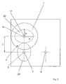
- FIG. 1 Shown in FIG. 1 is an embodiment of the device according to the invention, which serves to generate a flow movement of the fluid enclosing the drive body 40.
- the configured as Oloid drive body 40 is such arranged that its central part forms the middle member of a consisting of three members, everting joint system.
- the two outer members are configured as U-shaped drive levers 30, 31, which are arranged on their legs, each having two front, free ends 34, 35 and at their connecting webs each have a rear end 32, 33.
- the rear ends 32; 33 of the two drive levers 30, 31 are each by means of a first axis of rotation 11, 12, each with a front end 9; 10 of two parallel shafts 3, 4 movably connected.
- the first two axes of rotation 11, 12 are so connected to the drive levers 30, 31, that the first, connected to the first drive lever 30 axis of rotation 11 is perpendicular to a plane defined by the legs and the connecting web of the drive lever 30 level 36, 37 and with the second drive lever 31 connected, the first axis of rotation 12 is perpendicular to a plane defined by the legs and the connecting web of the second drive lever 31 level 37.
- the drive body 40 is connected by means of two second, at the front ends 34, 35 of the drive lever 30, 31 rotatably arranged axes of rotation 13, 14 movably connected to the drive levers 30, 31,.
- the two second axes of rotation 13, 14 are skewed to each other and have a distance A to each other. This distance A corresponds here to the distance B.
- the drive levers 30, 31 and the central part of the drive body 40 designed as an Oloid between the two second pivot axes 13, 14 form the three links of an invertible joint system, the distance between the two parallel shafts 3, 4 results.
- the rear ends (not shown) of the two parallel shafts 3, 4 are rotatably mounted in a gear box 15 about their longitudinal axes 5, 6.
- only the first shaft 3 is connected by means of an oval gears 20 having transmission 2 to the drive shaft 16 of the drive means designed as a motor 1.
- the longitudinal axes 5, 17 of the first shaft 3 and the drive shaft 16 are spaced by a distance Z corresponding to the sum of the semi-minor axis b and the major semiaxis a of the two oval gears 20 ', 20 ".
- FIG. 3 shows a perspective view of the drive body 40 configured as an oid.
- the development of this oloid is shown in FIG.
- the unwound surface 25 of the oloid is composed of a rectangular central element 26 and four, each on the long sides of the rectangular central element 26 arranged quarter-circle-shaped elements 27 together.
- the rectangular central element 26 has a length 1 and a width b, in which case the width b corresponds to the distance A (FIG. 1) between the two second rotary axes 13, 14.
- the centers 28 of the quarter circle-shaped elements 27 are arranged so that they are spaced on the one long side of the rectangular central element 26 by the radius r from the ends of the long sides while on the other long side of the rectangular central element 26 two of the centers 28 with the corners between the long and short sides of the rectangular central element 26 coincide and a further, third center 28 is disposed on half the length I of the long side of the rectangular central element 26.
- FIG. 5 shows an embodiment of the transmission 2 which differs from the embodiment shown in FIG. 2 only in that both shafts 3, 4 are driven by the drive shaft 16 by means of the transmission 2.
- an intermediate gear with four circular gears 21 is disposed between the drive shaft 16 and another, parallel to the drive shaft 16 uniform shaft 18.
- the longitudinal axes 5, 6, 17, 19 of the drive shaft 16, the second uniformly rotating shaft 18, and the two non-uniformly rotating shafts 3, 4 are arranged parallel and at the corners of a rectangle with the height Z.
- the two oval gears 20 ', 20 ", which for torque transmission between the first Shaft 3 and the drive shaft 16 are arranged with respect to their semi-axes a; b (Fig. 2) arranged rotated by 90 ° to each other.
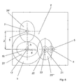
- FIG. 6 another embodiment of the transmission 2 is shown, which differs from the embodiment shown in Figure 2 in that the torque transmission of drive shaft 16 connected to the drive means 1 takes place on both shafts 3, 4 by means of toothed wheels 20, 21.
- the oval gears 20 are here designed such that the ratio between the small semiaxis b and the large semiaxis a is 1: ⁇ 2.
- the longitudinal axes 5; 6; 17; 23 of the drive shaft 16, the first and second shaft 5, 6 and the Hilfswel le 22 are parallel, wherein between the drive shaft 16 and the first shaft 3 is a distance Z, which corresponds to the sum of the half-axes a; b of the two oval gears 20 ', 20 ".
- the drive shaft 16 and the auxiliary shaft 22 are also spaced from each other by the distance Z.
- the circular gears 21 ', 21 “serve to produce the necessary direction of rotation for the two shafts 3, 4 and are in their diameter at the necessary distance between the two shafts 3; 4 adapted.
- Fig. 7 an embodiment of the transmission 2 is shown, which differs from the embodiment shown in Fig. 2 only in that the torque transmission from the drive shaft 16 to the first shaft 3 via two oval gears 20 ', 20 "takes place and at the same time a torque transmission from the drive shaft 16 to the second shaft 4 via two oval gears 20 '' ', 20' '' 'and two circular gears 21', 21 "takes place.
- Both pairs of oval gears 20 ', 20 ", 20"', 20 “” are designed such that the ratio between the small half-axes b and the major half-axes a is 1: ⁇ 2.
- the two oval gears 20 ', 20' "connected to the drive shaft 16 are rotated by 90 ° with respect to their semiaxes a; b. Furthermore, an auxiliary shaft 22 is arranged between the drive shaft 16 and the second shaft 4, once with the oval gear 20 "" and the circular gearwheel 21 'are connected, and the two circular gearwheels 21', 21 "serve to counteract the direction of rotation of the two shafts 3, 4.
- the drive shaft 16, the first and the second shaft 3, 4 and the auxiliary shaft 22 are arranged so that their longitudinal axes 5, 6, 17, 23 are parallel.
- FIG. 8 an embodiment of the transmission 2 is shown, which differs from the embodiment shown in Figure 2 only in that the torque transmission between the drive shaft 16 and each of the two shafts 3, 4 by means of two oval gears 20 ', 20 "; 20" ', 20 “”.
- an oval gear 20 ' is connected to the drive shaft 16
- two oval gears 20 ", 20"' are connected to the first shaft 3
- an oval gear 20 "" is connected to the second shaft 4.
- the two oval gears 20 ", 20 '" connected to the first shaft 3 are rotated by 90 ° with respect to their semiaxes.
- gears 20 ', 20 "connected to the drive shaft 16 and the first gear connected to the first shaft 3 are configured so that the ratio between the small half-axes b and the major half-axes a is 1: ⁇ 2, while the second is the first Shaft 3 connected oval gear 20 '"and connected to the second shaft 4 oval gear 20" "are designed such that the ratio between the small half-axes b and the major half-axes a 1: 2.
Landscapes
- Engineering & Computer Science (AREA)
- General Engineering & Computer Science (AREA)
- Chemical & Material Sciences (AREA)
- Chemical Kinetics & Catalysis (AREA)
- Mechanical Engineering (AREA)
- Gear Transmission (AREA)
- Massaging Devices (AREA)
- Transmission Devices (AREA)
- Percussion Or Vibration Massage (AREA)
Applications Claiming Priority (1)
| Application Number | Priority Date | Filing Date | Title |
|---|---|---|---|
| PCT/CH2003/000235 WO2004090383A1 (de) | 2003-04-10 | 2003-04-10 | Vorrichtung zur erzeugung von pulsierenden bewegungen |
Publications (2)
| Publication Number | Publication Date |
|---|---|
| EP1618319A1 EP1618319A1 (de) | 2006-01-25 |
| EP1618319B1 true EP1618319B1 (de) | 2006-08-16 |
Family
ID=33136738
Family Applications (1)
| Application Number | Title | Priority Date | Filing Date |
|---|---|---|---|
| EP03709538A Expired - Lifetime EP1618319B1 (de) | 2003-04-10 | 2003-04-10 | Vorrichtung zur erzeugung von pulsierenden bewegungen |
Country Status (9)
| Country | Link |
|---|---|
| US (1) | US7670043B2 (da) |
| EP (1) | EP1618319B1 (da) |
| AT (1) | ATE336672T1 (da) |
| AU (1) | AU2003213967A1 (da) |
| CA (1) | CA2521894C (da) |
| DE (1) | DE50304696D1 (da) |
| DK (1) | DK1618319T3 (da) |
| ES (1) | ES2271538T3 (da) |
| WO (1) | WO2004090383A1 (da) |
Cited By (1)
| Publication number | Priority date | Publication date | Assignee | Title |
|---|---|---|---|---|
| WO2019020835A1 (de) | 2017-07-28 | 2019-01-31 | Neuguss Verwaltungsgesellschaft Mbh | Verfahren und vorrichtungen zur nahezu scherkräftefreien durchmischung eines in einem behälter befindlichen mediums |
Families Citing this family (6)
| Publication number | Priority date | Publication date | Assignee | Title |
|---|---|---|---|---|
| ATE336672T1 (de) * | 2003-04-10 | 2006-09-15 | Oloid Ag | Vorrichtung zur erzeugung von pulsierenden bewegungen |
| US8361588B2 (en) | 2010-12-17 | 2013-01-29 | D Amario Nina | Rotating device |
| EP2823297B1 (en) | 2012-03-05 | 2023-04-19 | Boehringer Ingelheim International GmbH | Method for the evaluation of the colloidal stability of a liquid pharmaceutical composition |
| CN106622092B (zh) * | 2016-12-07 | 2018-07-10 | 无锡同心塑料制品有限公司 | 一种用于聚氨酯泡沫塑料化学发泡法的反应釜 |
| CN109653178B (zh) * | 2018-12-27 | 2021-02-26 | 上海理工大学 | 一种双伺服电机驱动的防缠绕除藻机 |
| CN109653173B (zh) * | 2018-12-27 | 2021-02-26 | 上海理工大学 | 一种伺服电机驱动的防缠绕除藻机 |
Family Cites Families (30)
| Publication number | Priority date | Publication date | Assignee | Title |
|---|---|---|---|---|
| US2302804A (en) * | 1939-02-05 | 1942-11-24 | Schatz Paul | Mechanism producing wavering and rotating movements of receptacles |
| CH242218A (de) * | 1942-06-04 | 1946-04-30 | Schatz Paul | Mechanismus zur Erzeugung einer taumelnden und schwenkenden Bewegung. |
| CH361701A (de) * | 1958-02-06 | 1962-04-30 | Schatz Paul | Auf dem Prinzip der umstülpbaren Kette beruhende Vorrichtung zur Erzeugung einer taumelnden und rotierenden Körperbewegung |
| DE1207750B (de) * | 1962-07-13 | 1965-12-23 | Bachofen Willy A | Auf dem Prinzip der umstuelpbaren Kette beruhende Vorrichtung zur Erzeugung einer taumelnden und rotierenden Koerperbewegung |
| CH399110A (de) * | 1962-07-13 | 1966-03-31 | Bachofen Willy A Fa | Auf dem Prinzip der umstülpbaren Kette beruhende Vorrichtung zur Erzeugung einer taumelnden und rotierenden Körperbewegung |
| CH500000A (de) * | 1968-08-03 | 1970-12-15 | Schatz Paul | Hilfsmittel zur Erzeugung einer taumelnden Bewegung |
| CH555490A (de) * | 1972-04-19 | 1974-10-31 | Schatz Paul | Vorrichtung zur erzeugung einer taumelnden bewegung. |
| SU762949A1 (ru) * | 1975-08-06 | 1980-09-15 | Kz Selskokhoz I | СМЕСИТЕЛЬ А, -ф 2 |
| SU643305A1 (ru) * | 1976-12-17 | 1979-01-25 | Казанский Сельскохозяйственный Институт Имени М.Горького | Устройство дл галтовки деталей |
| SU780871A1 (ru) * | 1978-03-03 | 1980-11-25 | Казанский Сельскохозяйственный Институт Им. М.Горького | Смеситель |
| SU730548A2 (ru) * | 1978-06-08 | 1980-04-30 | Казанский Сельскохозяйственный Институт Им. М.Горького | Устройство дл галтовки деталей |
| SU755577A1 (ru) * | 1978-06-27 | 1980-08-25 | Kazak Znak Pocheta Selskokhoz | Смеситель 1 |
| DE2842110C3 (de) * | 1978-09-27 | 1981-07-09 | Siemens AG, 1000 Berlin und 8000 München | Abgleichen der Schwingfrequenz von als Dickenscherungsschwinger verwendeten plattenförmigen Resonatoren |
| DE3034331D2 (en) * | 1979-03-01 | 1982-02-11 | Buergel Ag | Driving process and device for a rigid body to provide a transfer motion |
| SU797878A1 (ru) * | 1979-03-12 | 1981-01-25 | Казанский Ордена "Знак Почета"Сельскохозяйственный Институт Им. M.Горького | Смеситель |
| SU795958A1 (ru) * | 1979-03-26 | 1981-01-18 | Казанский Ордена "Знак Почета"Сельскохозяйственный Институтим.M.Горького | Смеситель |
| SU818831A2 (ru) * | 1979-05-15 | 1981-04-07 | Казанский Ордена Знак Почета Сельскохо-Зяйственный Институт Им. Горького | Устройство дл галтовки деталей |
| DE3434064A1 (de) * | 1984-09-17 | 1986-03-27 | Oloid Ag, Basel | Vorrichtung zum antrieb eines koerpers, der eine taumelnde und rotierende bewegung ausfuehrt |
| DE3542285C1 (de) * | 1985-11-29 | 1986-08-21 | Oloid Ag, Basel | Vorrichtung zum Antrieb eines Koerpers,der eine taumelnde und rotierende Bewegung ausfuehrt |
| DE3807658A1 (de) * | 1988-03-09 | 1989-09-21 | Zimmermann Wolfgang | Der sto-mischer |
| SU1607922A1 (ru) * | 1989-01-02 | 1990-11-23 | Предприятие П/Я А-1297 | Смеситель |
| ATE128637T1 (de) * | 1992-07-20 | 1995-10-15 | Bioengineering Ag | Vorrichtung zum antrieb eines taumelkörpers. |
| EP0604600B1 (de) * | 1992-07-20 | 1995-10-04 | Bioengineering AG | Vorrichtung zum antrieb eines taumelkörpers |
| CA2119472A1 (en) * | 1992-07-24 | 1994-02-03 | Pio Meyer | Apparatus for driving a wobbling body |
| US5360265A (en) * | 1992-12-15 | 1994-11-01 | Cruse Donald I | Apparatus with inversion linkage mechanism |
| US5466124A (en) * | 1993-03-05 | 1995-11-14 | Dettwiler; Hermann | Device for generating an inversion-kinematic movement |
| AU3535197A (en) | 1997-07-25 | 1999-02-16 | Abt & Fritschi Gmbh | Gear with oval pinions |
| JPH11319879A (ja) * | 1998-05-12 | 1999-11-24 | Unitika Ltd | 排水処理方法および排水処理装置 |
| DE59900373D1 (de) * | 1998-12-24 | 2001-12-06 | Oloid Ag Basel | Antrieb für inversionskinematische vorrichtung |
| ATE336672T1 (de) * | 2003-04-10 | 2006-09-15 | Oloid Ag | Vorrichtung zur erzeugung von pulsierenden bewegungen |
-
2003
- 2003-04-10 AT AT03709538T patent/ATE336672T1/de active
- 2003-04-10 DE DE50304696T patent/DE50304696D1/de not_active Expired - Lifetime
- 2003-04-10 EP EP03709538A patent/EP1618319B1/de not_active Expired - Lifetime
- 2003-04-10 AU AU2003213967A patent/AU2003213967A1/en not_active Abandoned
- 2003-04-10 US US10/552,648 patent/US7670043B2/en not_active Expired - Fee Related
- 2003-04-10 DK DK03709538T patent/DK1618319T3/da active
- 2003-04-10 WO PCT/CH2003/000235 patent/WO2004090383A1/de not_active Ceased
- 2003-04-10 ES ES03709538T patent/ES2271538T3/es not_active Expired - Lifetime
- 2003-04-10 CA CA2521894A patent/CA2521894C/en not_active Expired - Fee Related
Cited By (1)
| Publication number | Priority date | Publication date | Assignee | Title |
|---|---|---|---|---|
| WO2019020835A1 (de) | 2017-07-28 | 2019-01-31 | Neuguss Verwaltungsgesellschaft Mbh | Verfahren und vorrichtungen zur nahezu scherkräftefreien durchmischung eines in einem behälter befindlichen mediums |
Also Published As
| Publication number | Publication date |
|---|---|
| ES2271538T3 (es) | 2007-04-16 |
| US20060166612A1 (en) | 2006-07-27 |
| CA2521894C (en) | 2011-01-04 |
| CA2521894A1 (en) | 2004-10-21 |
| ATE336672T1 (de) | 2006-09-15 |
| EP1618319A1 (de) | 2006-01-25 |
| DK1618319T3 (da) | 2006-12-18 |
| DE50304696D1 (de) | 2006-09-28 |
| AU2003213967A1 (en) | 2004-11-01 |
| US7670043B2 (en) | 2010-03-02 |
| WO2004090383A1 (de) | 2004-10-21 |
Similar Documents
| Publication | Publication Date | Title |
|---|---|---|
| DE60312047T2 (de) | Rotorgesteuertes getriebe | |
| DE3939187A1 (de) | Gegenlaufschrauben-schiffsantrieb | |
| DE3710582A1 (de) | Permanenter vierradantrieb fuer ein kraftfahrzeug | |
| EP1618319B1 (de) | Vorrichtung zur erzeugung von pulsierenden bewegungen | |
| DE3913588A1 (de) | Stufenlos regelbares flachriemenuebersetzungsgetriebe mit einer geschwindigkeitssteuerung | |
| EP0075667A1 (de) | Stellantrieb mit einem Planetengetriebe | |
| DE3721064A1 (de) | Spielfreies planetengetriebe | |
| DE69907055T2 (de) | Parallelachsiges Stirnrad-Ausgleichsgetriebe | |
| DE3729134A1 (de) | Gelenkbeschlag fuer einen fahrzeugsitz | |
| DE102004018247B3 (de) | Vorrichtung zur Bewegungsumwandlung, An- und Abtrieb von sechsgliedrigen Gelenkringen | |
| DE4341112C1 (de) | Umlaufrädergetriebe mit stufenloser Drehzahlverstellung | |
| CH659867A5 (de) | Freilaufkupplung. | |
| DE4337858C2 (de) | Mechanischer Drehmomentwandler | |
| DE10251388B4 (de) | Rotor einer Windkraftanlage | |
| DE102009026780A1 (de) | Planetengetriebeanordnung | |
| DE2808769A1 (de) | Schwenkkolben-maschine | |
| DE102015121995B3 (de) | Getriebe für eine Auftriebsfläche, Schlagantrieb und Unterwasser- oder Luftfahrzeug | |
| EP1941184B1 (de) | Kontinuierlich variierbare übersetzung | |
| DE875114C (de) | Stufenlos mit rein mechanischen Mitteln regelbares Getriebe | |
| EP1007868A1 (de) | Getriebe mit ovalen zahnrädern | |
| DE69006723T2 (de) | Betätigungs-mechanismus. | |
| DE102020112563A1 (de) | Getriebebeschlag für einen fahrzeugsitz, sowie fahrzeugsitz | |
| CH684357A5 (de) | Stufenlos verstellbares Getriebe. | |
| DE875102C (de) | Freiflugkolbenmaschine mit gegenlaeufigen Flugmassen | |
| DE102019115283A1 (de) | Ein Differentialgetriebe und ein Fahrzeug mit einem Differentialgetriebe |
Legal Events
| Date | Code | Title | Description |
|---|---|---|---|
| PUAI | Public reference made under article 153(3) epc to a published international application that has entered the european phase |
Free format text: ORIGINAL CODE: 0009012 |
|
| 17P | Request for examination filed |
Effective date: 20050929 |
|
| AK | Designated contracting states |
Kind code of ref document: A1 Designated state(s): AT BE BG CH CY CZ DE DK EE ES FI FR GB GR HU IE IT LI LU MC NL PT RO SE SI SK TR |
|
| AX | Request for extension of the european patent |
Extension state: AL LT LV MK |
|
| GRAP | Despatch of communication of intention to grant a patent |
Free format text: ORIGINAL CODE: EPIDOSNIGR1 |
|
| GRAS | Grant fee paid |
Free format text: ORIGINAL CODE: EPIDOSNIGR3 |
|
| GRAA | (expected) grant |
Free format text: ORIGINAL CODE: 0009210 |
|
| DAX | Request for extension of the european patent (deleted) | ||
| AK | Designated contracting states |
Kind code of ref document: B1 Designated state(s): AT BE BG CH CY CZ DE DK EE ES FI FR GB GR HU IE IT LI LU MC NL PT RO SE SI SK TR |
|
| PG25 | Lapsed in a contracting state [announced via postgrant information from national office to epo] |
Ref country code: IT Free format text: LAPSE BECAUSE OF FAILURE TO SUBMIT A TRANSLATION OF THE DESCRIPTION OR TO PAY THE FEE WITHIN THE PRESCRIBED TIME-LIMIT;WARNING: LAPSES OF ITALIAN PATENTS WITH EFFECTIVE DATE BEFORE 2007 MAY HAVE OCCURRED AT ANY TIME BEFORE 2007. THE CORRECT EFFECTIVE DATE MAY BE DIFFERENT FROM THE ONE RECORDED. Effective date: 20060816 Ref country code: RO Free format text: LAPSE BECAUSE OF FAILURE TO SUBMIT A TRANSLATION OF THE DESCRIPTION OR TO PAY THE FEE WITHIN THE PRESCRIBED TIME-LIMIT Effective date: 20060816 Ref country code: SK Free format text: LAPSE BECAUSE OF FAILURE TO SUBMIT A TRANSLATION OF THE DESCRIPTION OR TO PAY THE FEE WITHIN THE PRESCRIBED TIME-LIMIT Effective date: 20060816 Ref country code: SI Free format text: LAPSE BECAUSE OF FAILURE TO SUBMIT A TRANSLATION OF THE DESCRIPTION OR TO PAY THE FEE WITHIN THE PRESCRIBED TIME-LIMIT Effective date: 20060816 |
|
| REG | Reference to a national code |
Ref country code: GB Ref legal event code: FG4D Free format text: NOT ENGLISH |
|
| REG | Reference to a national code |
Ref country code: CH Ref legal event code: EP |
|
| REG | Reference to a national code |
Ref country code: IE Ref legal event code: FG4D Free format text: LANGUAGE OF EP DOCUMENT: GERMAN |
|
| REF | Corresponds to: |
Ref document number: 50304696 Country of ref document: DE Date of ref document: 20060928 Kind code of ref document: P |
|
| PG25 | Lapsed in a contracting state [announced via postgrant information from national office to epo] |
Ref country code: BG Free format text: LAPSE BECAUSE OF FAILURE TO SUBMIT A TRANSLATION OF THE DESCRIPTION OR TO PAY THE FEE WITHIN THE PRESCRIBED TIME-LIMIT Effective date: 20061116 |
|
| REG | Reference to a national code |
Ref country code: SE Ref legal event code: TRGR |
|
| GBT | Gb: translation of ep patent filed (gb section 77(6)(a)/1977) |
Effective date: 20061113 |
|
| REG | Reference to a national code |
Ref country code: CH Ref legal event code: NV Representative=s name: DR. LUSUARDI AG |
|
| PG25 | Lapsed in a contracting state [announced via postgrant information from national office to epo] |
Ref country code: PT Free format text: LAPSE BECAUSE OF FAILURE TO SUBMIT A TRANSLATION OF THE DESCRIPTION OR TO PAY THE FEE WITHIN THE PRESCRIBED TIME-LIMIT Effective date: 20070116 |
|
| ET | Fr: translation filed | ||
| REG | Reference to a national code |
Ref country code: ES Ref legal event code: FG2A Ref document number: 2271538 Country of ref document: ES Kind code of ref document: T3 |
|
| PLBE | No opposition filed within time limit |
Free format text: ORIGINAL CODE: 0009261 |
|
| STAA | Information on the status of an ep patent application or granted ep patent |
Free format text: STATUS: NO OPPOSITION FILED WITHIN TIME LIMIT |
|
| 26N | No opposition filed |
Effective date: 20070518 |
|
| PG25 | Lapsed in a contracting state [announced via postgrant information from national office to epo] |
Ref country code: GR Free format text: LAPSE BECAUSE OF FAILURE TO SUBMIT A TRANSLATION OF THE DESCRIPTION OR TO PAY THE FEE WITHIN THE PRESCRIBED TIME-LIMIT Effective date: 20061117 |
|
| PG25 | Lapsed in a contracting state [announced via postgrant information from national office to epo] |
Ref country code: EE Free format text: LAPSE BECAUSE OF FAILURE TO SUBMIT A TRANSLATION OF THE DESCRIPTION OR TO PAY THE FEE WITHIN THE PRESCRIBED TIME-LIMIT Effective date: 20060816 |
|
| REG | Reference to a national code |
Ref country code: CH Ref legal event code: PUE Owner name: HORTIMAX B.V. Free format text: OLOID AG#JURASTRASSE 50#4053 BASEL (CH) -TRANSFER TO- HORTIMAX B.V.#VLIELANDSEWEG 20#2640 AB PIJNACKER (NL) |
|
| REG | Reference to a national code |
Ref country code: GB Ref legal event code: 732E |
|
| NLS | Nl: assignments of ep-patents |
Owner name: HORTIMAX B.V. Effective date: 20081003 |
|
| PG25 | Lapsed in a contracting state [announced via postgrant information from national office to epo] |
Ref country code: MC Free format text: LAPSE BECAUSE OF NON-PAYMENT OF DUE FEES Effective date: 20070430 |
|
| REG | Reference to a national code |
Ref country code: FR Ref legal event code: TP |
|
| REG | Reference to a national code |
Ref country code: ES Ref legal event code: PC2A |
|
| PG25 | Lapsed in a contracting state [announced via postgrant information from national office to epo] |
Ref country code: CY Free format text: LAPSE BECAUSE OF FAILURE TO SUBMIT A TRANSLATION OF THE DESCRIPTION OR TO PAY THE FEE WITHIN THE PRESCRIBED TIME-LIMIT Effective date: 20060816 |
|
| PG25 | Lapsed in a contracting state [announced via postgrant information from national office to epo] |
Ref country code: HU Free format text: LAPSE BECAUSE OF FAILURE TO SUBMIT A TRANSLATION OF THE DESCRIPTION OR TO PAY THE FEE WITHIN THE PRESCRIBED TIME-LIMIT Effective date: 20070217 Ref country code: TR Free format text: LAPSE BECAUSE OF FAILURE TO SUBMIT A TRANSLATION OF THE DESCRIPTION OR TO PAY THE FEE WITHIN THE PRESCRIBED TIME-LIMIT Effective date: 20060816 |
|
| PGFP | Annual fee paid to national office [announced via postgrant information from national office to epo] |
Ref country code: LU Payment date: 20110429 Year of fee payment: 9 |
|
| PGFP | Annual fee paid to national office [announced via postgrant information from national office to epo] |
Ref country code: IE Payment date: 20110426 Year of fee payment: 9 |
|
| PGFP | Annual fee paid to national office [announced via postgrant information from national office to epo] |
Ref country code: IT Payment date: 20110428 Year of fee payment: 9 |
|
| PGFP | Annual fee paid to national office [announced via postgrant information from national office to epo] |
Ref country code: FI Payment date: 20120411 Year of fee payment: 10 |
|
| PGFP | Annual fee paid to national office [announced via postgrant information from national office to epo] |
Ref country code: ES Payment date: 20120425 Year of fee payment: 10 |
|
| REG | Reference to a national code |
Ref country code: IE Ref legal event code: MM4A |
|
| PG25 | Lapsed in a contracting state [announced via postgrant information from national office to epo] |
Ref country code: IE Free format text: LAPSE BECAUSE OF NON-PAYMENT OF DUE FEES Effective date: 20120410 |
|
| PG25 | Lapsed in a contracting state [announced via postgrant information from national office to epo] |
Ref country code: IT Free format text: LAPSE BECAUSE OF NON-PAYMENT OF DUE FEES Effective date: 20120410 |
|
| PGFP | Annual fee paid to national office [announced via postgrant information from national office to epo] |
Ref country code: AT Payment date: 20120411 Year of fee payment: 10 |
|
| PGFP | Annual fee paid to national office [announced via postgrant information from national office to epo] |
Ref country code: DK Payment date: 20130418 Year of fee payment: 11 Ref country code: CZ Payment date: 20130405 Year of fee payment: 11 |
|
| REG | Reference to a national code |
Ref country code: AT Ref legal event code: MM01 Ref document number: 336672 Country of ref document: AT Kind code of ref document: T Effective date: 20130430 |
|
| PG25 | Lapsed in a contracting state [announced via postgrant information from national office to epo] |
Ref country code: AT Free format text: LAPSE BECAUSE OF NON-PAYMENT OF DUE FEES Effective date: 20130430 |
|
| PG25 | Lapsed in a contracting state [announced via postgrant information from national office to epo] |
Ref country code: FI Free format text: LAPSE BECAUSE OF NON-PAYMENT OF DUE FEES Effective date: 20130410 |
|
| PG25 | Lapsed in a contracting state [announced via postgrant information from national office to epo] |
Ref country code: LU Free format text: LAPSE BECAUSE OF NON-PAYMENT OF DUE FEES Effective date: 20120410 |
|
| PG25 | Lapsed in a contracting state [announced via postgrant information from national office to epo] |
Ref country code: CZ Free format text: LAPSE BECAUSE OF NON-PAYMENT OF DUE FEES Effective date: 20140410 |
|
| REG | Reference to a national code |
Ref country code: DK Ref legal event code: EBP Effective date: 20140430 |
|
| PG25 | Lapsed in a contracting state [announced via postgrant information from national office to epo] |
Ref country code: DK Free format text: LAPSE BECAUSE OF NON-PAYMENT OF DUE FEES Effective date: 20140430 |
|
| REG | Reference to a national code |
Ref country code: ES Ref legal event code: FD2A Effective date: 20150527 |
|
| PG25 | Lapsed in a contracting state [announced via postgrant information from national office to epo] |
Ref country code: ES Free format text: LAPSE BECAUSE OF NON-PAYMENT OF DUE FEES Effective date: 20140411 |
|
| REG | Reference to a national code |
Ref country code: FR Ref legal event code: PLFP Year of fee payment: 13 |
|
| REG | Reference to a national code |
Ref country code: FR Ref legal event code: PLFP Year of fee payment: 14 |
|
| REG | Reference to a national code |
Ref country code: FR Ref legal event code: PLFP Year of fee payment: 15 |
|
| REG | Reference to a national code |
Ref country code: FR Ref legal event code: PLFP Year of fee payment: 16 |
|
| PGFP | Annual fee paid to national office [announced via postgrant information from national office to epo] |
Ref country code: NL Payment date: 20180418 Year of fee payment: 16 |
|
| PGFP | Annual fee paid to national office [announced via postgrant information from national office to epo] |
Ref country code: BE Payment date: 20180418 Year of fee payment: 16 |
|
| PGFP | Annual fee paid to national office [announced via postgrant information from national office to epo] |
Ref country code: SE Payment date: 20180418 Year of fee payment: 16 |
|
| PGFP | Annual fee paid to national office [announced via postgrant information from national office to epo] |
Ref country code: GB Payment date: 20180418 Year of fee payment: 16 |
|
| REG | Reference to a national code |
Ref country code: SE Ref legal event code: EUG |
|
| REG | Reference to a national code |
Ref country code: NL Ref legal event code: MM Effective date: 20190501 |
|
| REG | Reference to a national code |
Ref country code: BE Ref legal event code: MM Effective date: 20190430 |
|
| GBPC | Gb: european patent ceased through non-payment of renewal fee |
Effective date: 20190410 |
|
| PG25 | Lapsed in a contracting state [announced via postgrant information from national office to epo] |
Ref country code: NL Free format text: LAPSE BECAUSE OF NON-PAYMENT OF DUE FEES Effective date: 20190501 Ref country code: GB Free format text: LAPSE BECAUSE OF NON-PAYMENT OF DUE FEES Effective date: 20190410 Ref country code: SE Free format text: LAPSE BECAUSE OF NON-PAYMENT OF DUE FEES Effective date: 20190411 |
|
| PG25 | Lapsed in a contracting state [announced via postgrant information from national office to epo] |
Ref country code: BE Free format text: LAPSE BECAUSE OF NON-PAYMENT OF DUE FEES Effective date: 20190430 |
|
| PGFP | Annual fee paid to national office [announced via postgrant information from national office to epo] |
Ref country code: FR Payment date: 20220421 Year of fee payment: 20 Ref country code: DE Payment date: 20220420 Year of fee payment: 20 |
|
| PGFP | Annual fee paid to national office [announced via postgrant information from national office to epo] |
Ref country code: CH Payment date: 20220421 Year of fee payment: 20 |
|
| REG | Reference to a national code |
Ref country code: DE Ref legal event code: R071 Ref document number: 50304696 Country of ref document: DE |
|
| REG | Reference to a national code |
Ref country code: CH Ref legal event code: PL |