EP1618325B1 - Ventilanordnung - Google Patents
Ventilanordnung Download PDFInfo
- Publication number
- EP1618325B1 EP1618325B1 EP04729928A EP04729928A EP1618325B1 EP 1618325 B1 EP1618325 B1 EP 1618325B1 EP 04729928 A EP04729928 A EP 04729928A EP 04729928 A EP04729928 A EP 04729928A EP 1618325 B1 EP1618325 B1 EP 1618325B1
- Authority
- EP
- European Patent Office
- Prior art keywords
- valve body
- valve
- ports
- assembly according
- pipeline
- Prior art date
- Legal status (The legal status is an assumption and is not a legal conclusion. Google has not performed a legal analysis and makes no representation as to the accuracy of the status listed.)
- Expired - Lifetime
Links
- 230000015572 biosynthetic process Effects 0.000 claims description 7
- 238000005755 formation reaction Methods 0.000 claims description 7
- 239000012530 fluid Substances 0.000 abstract description 4
- 239000007788 liquid Substances 0.000 description 4
- 238000007789 sealing Methods 0.000 description 4
- 230000000712 assembly Effects 0.000 description 1
- 238000000429 assembly Methods 0.000 description 1
- 238000003780 insertion Methods 0.000 description 1
- 230000037431 insertion Effects 0.000 description 1
- 238000012423 maintenance Methods 0.000 description 1
- 230000002093 peripheral effect Effects 0.000 description 1
Images


Classifications
-
- F—MECHANICAL ENGINEERING; LIGHTING; HEATING; WEAPONS; BLASTING
- F16—ENGINEERING ELEMENTS AND UNITS; GENERAL MEASURES FOR PRODUCING AND MAINTAINING EFFECTIVE FUNCTIONING OF MACHINES OR INSTALLATIONS; THERMAL INSULATION IN GENERAL
- F16K—VALVES; TAPS; COCKS; ACTUATING-FLOATS; DEVICES FOR VENTING OR AERATING
- F16K5/00—Plug valves; Taps or cocks comprising only cut-off apparatus having at least one of the sealing faces shaped as a more or less complete surface of a solid of revolution, the opening and closing movement being predominantly rotary
- F16K5/06—Plug valves; Taps or cocks comprising only cut-off apparatus having at least one of the sealing faces shaped as a more or less complete surface of a solid of revolution, the opening and closing movement being predominantly rotary with plugs having spherical surfaces; Packings therefor
- F16K5/0626—Easy mounting or dismounting means
- F16K5/0631—Easy mounting or dismounting means between two flanges
-
- Y—GENERAL TAGGING OF NEW TECHNOLOGICAL DEVELOPMENTS; GENERAL TAGGING OF CROSS-SECTIONAL TECHNOLOGIES SPANNING OVER SEVERAL SECTIONS OF THE IPC; TECHNICAL SUBJECTS COVERED BY FORMER USPC CROSS-REFERENCE ART COLLECTIONS [XRACs] AND DIGESTS
- Y10—TECHNICAL SUBJECTS COVERED BY FORMER USPC
- Y10T—TECHNICAL SUBJECTS COVERED BY FORMER US CLASSIFICATION
- Y10T137/00—Fluid handling
- Y10T137/8593—Systems
- Y10T137/87917—Flow path with serial valves and/or closures
-
- Y—GENERAL TAGGING OF NEW TECHNOLOGICAL DEVELOPMENTS; GENERAL TAGGING OF CROSS-SECTIONAL TECHNOLOGIES SPANNING OVER SEVERAL SECTIONS OF THE IPC; TECHNICAL SUBJECTS COVERED BY FORMER USPC CROSS-REFERENCE ART COLLECTIONS [XRACs] AND DIGESTS
- Y10—TECHNICAL SUBJECTS COVERED BY FORMER USPC
- Y10T—TECHNICAL SUBJECTS COVERED BY FORMER US CLASSIFICATION
- Y10T137/00—Fluid handling
- Y10T137/8593—Systems
- Y10T137/87917—Flow path with serial valves and/or closures
- Y10T137/87925—Separable flow path section, valve or closure in each
- Y10T137/87933—Common joint and valve seat faces, or sections joined by closing members
Definitions
- the invention to which this application relates is to a valve assembly and particularly to improvements in the design of a valve assembly commonly known as a double block and bleed valve.
- double block and bleed valve assembly is well known and is extensively used in pipelines such as those used for carrying oil supply.
- the use of double block and bleed valves is generally regarded as the best option in terms of safety and ease of maintenance.
- the valves typically, although not exclusively, include two trunnion mounted balls wherein the respective seals of each valve are moved onto the ball within the valve body to bring about the sealing or closure of the valve.
- a problem which is general to all double block and bleed valves is that the length of the same is required to comply with the International Standard ANSI B16.10. This acts as a restriction on the design possibilities for the valves and can be troublesome to valve manufacturers in having to ensure that the valve components can be accommodated in the valve body whilst ensuring that the length restrictions can still be achieved.
- a double block and bleed valve according to the preamble of claim 1 is disclosed in the applicant's patent EP1038132 .
- This form of valve has been found to be extremely successful commercially due to the advantages in practical usage.
- Reference to this patent and Prior art Figure A illustrates one form of double block and bleed valve arrangement with the valve body formed by two parts joined together at an interface intermediate the ends of the valve body. At each end of the body are provided flange formations X,Y to allow the valve to be attached to the pipeline flanges via bolts.
- This valve also has the significant advantage of only having a single joint i.e at the interface. This is of advantage over the "double retainer" form of valves which have two pressurised joints instead of just one. As a result it can reasonably be stated that the valve in accordance with the patent is 50% safer.
- valve body is a unitary member having a bore along the length thereof and the body is connected directly to the pipeline without flanges on the valve.
- the valve components are required to be inserted into the bore from one end of the body and locked therein by the insertion of a sealing ring into the end of the bore.
- the sealing ring is held in that position, typically by a threaded arrangement or other locking means.
- a problem with this arrangement is that there is a significant risk of leakage of the liquid or gas passing through the bore, through a passage defined between the sealing ring and the bore in the valve body.
- the aim of the present invention is to provide an improvement to a double block and bleed valve assembly which allows additional space to be provided for the location of the valve components within the valve body while at the same time ensuring that the valve still meets the criteria of ANSI 16.10 in terms of the length of the same and that fluid leakage is still prevented or minimised.
- a valve assembly comprising a valve body having a bore running along the length thereof, said bore controlled between open and closed positions by two selectively operable valve arrangements positioned within the valve body, said body formed from at least first and second valve body parts, said parts joined at an interface intermediate the ends of the valve body and said valve body includes at both ends thereof, a series of spaced ports, said ports depending inwardly from the end face into the respective valve body part and provided for the reception of location means to allow the same to be attached to a pipeline flange and characterised in that depending from at least one of said ends there are provided a series of channels running parallel with and offset from the said ports, said channels receiving location means which pass from said end along said respective channels and into respective apertures in the other valve body part to allow the valve body parts to be secured together.
- valve assembly is a double block and bleed valve assembly.
- the series of ports are provided at first and second opposing end faces of the valve body to allow the location of the first and second end faces of the valve body with first and second pipeline ends respectively.
- the ports are blind ports in that their length is shorter than the length of the valve body part in which the same is located.
- valve body parts are joined at the interface to form the valve body by means of bolts passing though a series of spaced, matching, channels.
- interface lies perpendicular to the longitudinal axis of the bore passing through the valve body.
- the location of and spacing between the ports at the end of the valve body is such that the same are offset with respect to the locations of the channels which receive the bolts for joining the valve body parts together at the interface intermediate the ends of the valve body.
- a bleed valve is mounted on one of the two parts of the valve body.
- the interface between the valve body parts is typically formed so as to minimise the risk of leakage of the liquid or gas from the bore through the interface to atmosphere.
- the joint is in accordance with that described in the applicant's patent referred to previously.
- each port is provided at each end of the valve body to allow the valve body to be connected to the adjacent end of a pipeline, each port equally spaced around a circular path adjacent the periphery of the valve body end face.
- valve body has a length which matches the required length in accordance with ANSI 16.10.
- a double block and bleed valve assembly for connection to first and second pipeline ends, said pipeline ends provided with a flange with apertures at spaced locations for the reception of location means which pass through said apertures and into spaced ports provided in the respective ends of the valve body and wherein the valve assembly body is of substantially the same outer surface dimensions along the length thereof.
- valve body can be provided along the entire length of the valve assembly and can be of substantially the same shape and dimensions from end face to end face of the valve assembly. This therefore means that the capacity of the interior of the valve body is increased. This is in contrast to the prior art arrangements which do require the provision of flange formations for joining with the matching flanges at the pipeline ends.
- the outer dimension of the valve body is similar to the outer dimension of the pipeline flange.
- ports depend inwardly from the end face and are provided for the reception of location means to pass through the matching respective apertures provided on a pipeline flange and said ports located wholly within the valve body to allow the valve to be directly joined with said pipeline via contact between the end face of the valve body and the pipeline flange.
- the assembly is connected to a pipeline with at least one of said double block and bleed valve assemblies fitted thereto, said assembly comprising a valve body having a bore running along the length thereof, said bore controlled between open and closed position by two selectively operable valve arrangements positioned along the bore to allow the selective flow of a fluid along the said pipeline and valve bore when the valve is open, and characterised in that the valve body includes at the end faces which are joined to the pipeline ends, a series of spaced ports, each of said ports having an opening at the end face of the valve body and depending inwardly from the end face into the valve body for the reception of a locating bolt which pass through an aperture provided in a flange at the pipeline end and into the port in the valve body to allow the valve to be joined with a pipeline end.
- valve body is formed from two body parts, said parts joined at an interface intermediate the end faces of the valve body.
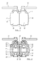
- FIG. 1 2 and 3 there is shown one embodiment of a double block and bleed valve assembly 1 in accordance with the invention.
- the assembly comprises a valve body 2 which in accordance with this embodiment of the invention extends along the length of the valve assembly.
- the valve body includes a bore 4 which passes along the length of the body and which allows the selective flow of a liquid or gas therealong.
- the bore also includes two inline block valves 6,8, each operable automatically and/or in this case via handles 10,12 respectively.
- the valves typically include a ball, not shown, which is trunnion mounted and each valve is moveable between an open position to allow the fluid to pass therethrough, and a closed position.
- a bleed valve 17 is also provided, in connection with the bore but mounted perpendicularly to the longitudinal axis 16 of the bore 4, which is a bleed valve 17. This is not described in any detail here as it operates in a conventional manner.
- the valve body 2 comprises two parts 18, 20.
- the parts are joined together once the valve components have been positioned in the respective positions within the valve body parts.
- the two parts 18,20 are then joined together at an interface 22, which is formed so as to minimise the opportunity for leakage of the liquid or gas from the bore through the interface join.
- the join is typically achieved via bolts located in a series of spaced channels 23, typically four, at the interface.
- the channels are located on the valve body part 20 in this embodiment and the bolts (not shown) pass along the channels, across the interface 22 and into threaded apertures 25 to engage the two parts 18,20 together in a sealed relationship at the interface.
- Figure 3 illustrates how the opening into the channels 23 are spaced in a circular path at the end face of the part 20.
- the valve body does not include or require flange formations at each end face to be provided to allow connection of the valve with the pipeline flanges at the ends of the pipelines 24,26.
- the connection of the valve with the pipeline flanges 28, 30 is achieved via a series of bolts 32.
- Each of the bolts 32 passes through one of a series of spaced apertures in the pipeline flange and then into one of a number of threaded ports 34 at the respective end faces 35,37 of the valve body.
- a series of the ports 34 are provided at each end 35, 37 of the valve body and they are spaced apart around a circular path 39 adjacent the peripheral edge of the end face. The number of ports and the spacing are provided to match those apertures provided as standard on the pipeline flanges 28,30.
- the valve is positioned in the space provided between the pipeline flanges 28,30 and the ports 34 matched with the apertures on the flanges.
- bolts can be introduced from the pipeline ends, through the apertures in the pipeline flanges and into the ports in the valve body.
- the ports 34 are threaded and therefore the screwing in of the bolts serves to secure and tighten the pipeline flanges to the respective end faces of the valve body and seal the valve to the pipeline.
- headless threaded shafts can be inserted into the threaded ports in the valve body and nuts subsequently tightened onto the shafts from the pipeline ends, to secure and fasten the valve in position with the pipeline flanges.
- the invention as herein described therefore provides a flangeless two part valve body which allows the advantages of assembly of a two part body, the advantages of the efficient seal between the two parts of the valve body to be combined with the direct connection of the valve body to the pipeline flanges, to be achieved in a valve which still meets the length and other requirements of ANSI 16.10.
- the lack of flanges means that there is greater space available in the valve body for the valve components to be provided and/ or further components to be incorporated into the valve body which otherwise could not be accommodated in conventional valve bodies which include flanges due the length constraints on the valve.
Landscapes
- Engineering & Computer Science (AREA)
- General Engineering & Computer Science (AREA)
- Mechanical Engineering (AREA)
- Valve Housings (AREA)
- Magnetically Actuated Valves (AREA)
- Compressor (AREA)
- Respiratory Apparatuses And Protective Means (AREA)
- Lift Valve (AREA)
Claims (13)
- Ventilbaugruppe, wobei die genannte Baugruppe einen Ventilkörper (2) mit einer über dessen Länge verlaufenden Bohrung (4) umfasst, wobei die genannte Bohrung von zwei in dem Ventilkörper positionierten, selektiv zu betätigenden Ventilanordnungen (6, 8) zwischen der offenen und der geschlossenen Position gesteuert werden kann, wobei der genannte Körper von wenigstens einem ersten und einem zweiten Ventilkörperteil (18, 20) gebildet wird, wobei die genannten Teile an einer Schnittstelle (22) zwischen den Enden des Ventilkörpers verbunden sind und der genannte Ventilkörper an seinen beiden Enden (35, 37) eine Reihe von beabstandeten Aufnahmen (34) aufweist, wobei die genannten Aufnahmen einwärts von der Endfläche in den jeweiligen Ventilkörperteil reichen und zum Aufnehmen eines Positionierungsmittels (32) vorgesehen sind, damit dieses an einem Pipeline-Flansch (28, 30) angebracht werden kann, und dadurch gekennzeichnet, dass von wenigstens einem der genannten Enden (35, 37) eine Reihe von Kanälen (23) vorgesehen ist, die parallel zu und versetzt von den genannten Aufnahmen (34) verlaufen, wobei der genannte Kanal Positionierungsmittel aufnimmt, die von dem genannten Ende entlang den jeweiligen Kanälen (23) und in jeweilige Löcher (25) in dem anderen Ventilkörperteil verlaufen, damit die Ventilkörperteile aneinander befestigt werden können.
- Baugruppe nach Anspruch 1, dadurch gekennzeichnet, dass die Positionierungsmittel (32) eine Reihe von Schraubbolzen sind, wobei jeder Schraubbolzen so ausgelegt ist, dass er durch ein passendes Loch in einem Flansch am Pipeline-Ende und in eine der Aufnahmen (34) in dem Ventilkörper (2) geht.
- Baugruppe nach Anspruch 1, dadurch gekennzeichnet, dass die in den jeweiligen Ventilkörperteilen (18, 20) vorgesehenen Aufnahmen (34) Blindaufnahmen sind.
- Baugruppe nach Anspruch 1, dadurch gekennzeichnet, dass die Schnittstelle (22) zwischen den Teilen (18, 20) im Wesentlichen lotrecht zur Längsachse der durch den Ventilkörper (2) gehenden Bohrung (4) liegt.
- Baugruppe nach Anspruch 1, dadurch gekennzeichnet, dass mehrere der genannten Aufnahmen (34) an dem einen Ende (35, 37) des Ventilkörpers (2) so voneinander beabstandet und/oder positioniert sind, dass die Aufnahmen (34) in Bezug auf die Kanäle (23), die die Positionierungsmittel zum Anbringen der Ventilkörperteile aneinander an der Schnittstelle aufnehmen, versetzt sind.
- Baugruppe nach Anspruch 1, dadurch gekennzeichnet, dass ein Ablassventil (17) an einem der beiden Teile (18, 20) des Ventilkörpers (2) montiert ist.
- Baugruppe nach Anspruch 1, dadurch gekennzeichnet, dass acht Fassungen (34) an jedem Ende (35, 37) vorgesehen sind, damit der Ventilkörper (2) mit dem Nachbarflansch (28, 39) einer Pipeline verbunden werden kann.
- Baugruppe nach Anspruch 1, dadurch gekennzeichnet, dass der Ventilkörper (2) eine Länge hat, die der gemäß ANSI 16.10 geforderten Länge entspricht.
- Baugruppe nach Anspruch 1, dadurch gekennzeichnet, dass die Außenfläche des Ventilkörpers (2) an und neben den jeweiligen Enden (35, 37) des Körpers (2) frei von nach außen vorstehenden Formationen ist.
- Baugruppe nach Anspruch 1, dadurch gekennzeichnet, dass die Ventilbaugruppe ein Doppelblock (6, 8) und ein Ablassventil (17) ist.
- Ventilbaugruppe nach Anspruch 10, dadurch gekennzeichnet, dass der Ventilkörper (2) im Wesentlichen dieselben Außenflächenabmessungen über seine Länge hat.
- Baugruppe nach Anspruch 11, dadurch gekennzeichnet, dass die Außenabmessung des Ventilkörpers (2) der Außenabmessung des Pipeline-Flansches (28, 30) ähnlich ist.
- Pipeline, die wenigstens eine Ventilbaugruppe gemäß den Ansprüchen 1-12 beinhaltet.
Applications Claiming Priority (2)
| Application Number | Priority Date | Filing Date | Title |
|---|---|---|---|
| GBGB0309660.9A GB0309660D0 (en) | 2003-04-29 | 2003-04-29 | Valve assembly |
| PCT/GB2004/001807 WO2004097275A1 (en) | 2003-04-29 | 2004-04-28 | Valve assembly |
Publications (2)
| Publication Number | Publication Date |
|---|---|
| EP1618325A1 EP1618325A1 (de) | 2006-01-25 |
| EP1618325B1 true EP1618325B1 (de) | 2008-02-27 |
Family
ID=9957272
Family Applications (1)
| Application Number | Title | Priority Date | Filing Date |
|---|---|---|---|
| EP04729928A Expired - Lifetime EP1618325B1 (de) | 2003-04-29 | 2004-04-28 | Ventilanordnung |
Country Status (6)
| Country | Link |
|---|---|
| US (1) | US7699074B2 (de) |
| EP (1) | EP1618325B1 (de) |
| AT (1) | ATE387600T1 (de) |
| DE (1) | DE602004012085T2 (de) |
| GB (1) | GB0309660D0 (de) |
| WO (1) | WO2004097275A1 (de) |
Families Citing this family (17)
| Publication number | Priority date | Publication date | Assignee | Title |
|---|---|---|---|---|
| GB0908259D0 (en) * | 2009-05-14 | 2009-06-24 | Xamol Ltd | Valve assembly |
| GB201015032D0 (en) * | 2010-09-10 | 2010-10-20 | Xamol Ltd | Valve assembly |
| EP2463560B1 (de) * | 2010-12-08 | 2018-07-11 | Cameron International Corporation | Kugelventil |
| GB2493152A (en) * | 2011-07-25 | 2013-01-30 | Aes Eng Ltd | Modular valve with block and bleed functions |
| FR2981720A1 (fr) | 2011-10-25 | 2013-04-26 | Total Sa | Robinet d'isolement |
| EP2667066B1 (de) | 2012-05-23 | 2018-01-17 | Cameron International Corporation | Schützende Frontdichtungsanordnung |
| EP2667067A1 (de) | 2012-05-23 | 2013-11-27 | Cameron International Corporation | Ventil mit adaptivem Frontdichtungsring |
| EP2667068B1 (de) | 2012-05-23 | 2018-02-14 | Cameron International Corporation | Ventil mit konturierter Bohrung zum Ablenken von Partikeln |
| CN103711931B (zh) * | 2014-01-03 | 2016-01-13 | 浙江中德自控科技股份有限公司 | 组合物料高温高压排渣球阀 |
| CN106090339B (zh) * | 2016-08-29 | 2018-06-22 | 浙江中德自控科技股份有限公司 | 气动控制组合阀体机构 |
| CN106090338B (zh) * | 2016-08-29 | 2018-06-22 | 浙江中德自控科技股份有限公司 | 气动控制阀 |
| CN106122568B (zh) * | 2016-08-29 | 2018-06-29 | 浙江中德自控科技股份有限公司 | 一种气动控制阀 |
| CN106195315B (zh) * | 2016-08-29 | 2018-06-29 | 浙江中德自控科技股份有限公司 | 一种气动控制组合阀体机构 |
| CN107143665A (zh) * | 2017-05-31 | 2017-09-08 | 九江中船消防设备有限公司 | 一种单阀座集成双球芯结构的一体化快关阀 |
| EP3695145B1 (de) | 2017-10-10 | 2024-03-06 | Cameron Technologies Limited | Konturierter integrierter sitz für ein kugelventil |
| PL234666B1 (pl) * | 2018-04-26 | 2020-03-31 | Aquael Janusz Jankiewicz Spolka Z Ograniczona Odpowiedzialnoscia | Filtr wody do akwarium |
| CN113775786A (zh) * | 2021-09-08 | 2021-12-10 | 哈电集团哈尔滨电站阀门有限公司 | 一种气动泄放装置及其工作方法 |
Family Cites Families (6)
| Publication number | Priority date | Publication date | Assignee | Title |
|---|---|---|---|---|
| US4890643A (en) | 1988-06-02 | 1990-01-02 | Mogas Industries, Inc. | Bi-directional sealing valve |
| NO170239C (no) * | 1990-03-19 | 1992-09-23 | Ingolf Klyde | Kuleventil |
| GB2274317A (en) * | 1993-01-15 | 1994-07-20 | Spirax Sarco Ltd | Condensate trap installations |
| GB9725990D0 (en) * | 1997-12-09 | 1998-02-04 | Alco Hi Tek Ltd | Valve |
| US6182696B1 (en) * | 1998-10-27 | 2001-02-06 | Nordstrom Valves, Inc. | Dual isolation valve with rectangular flow passageways |
| GB0024507D0 (en) * | 2000-10-06 | 2000-11-22 | Oliver Twinsafe Valves Ltd | An isolation valve assembly |
-
2003
- 2003-04-29 GB GBGB0309660.9A patent/GB0309660D0/en not_active Ceased
-
2004
- 2004-04-28 WO PCT/GB2004/001807 patent/WO2004097275A1/en not_active Ceased
- 2004-04-28 US US10/523,297 patent/US7699074B2/en not_active Expired - Fee Related
- 2004-04-28 DE DE602004012085T patent/DE602004012085T2/de not_active Expired - Lifetime
- 2004-04-28 AT AT04729928T patent/ATE387600T1/de not_active IP Right Cessation
- 2004-04-28 EP EP04729928A patent/EP1618325B1/de not_active Expired - Lifetime
Also Published As
| Publication number | Publication date |
|---|---|
| DE602004012085D1 (de) | 2008-04-10 |
| EP1618325A1 (de) | 2006-01-25 |
| GB0309660D0 (en) | 2003-06-04 |
| US7699074B2 (en) | 2010-04-20 |
| WO2004097275A1 (en) | 2004-11-11 |
| ATE387600T1 (de) | 2008-03-15 |
| DE602004012085T2 (de) | 2009-03-26 |
| US20060048825A1 (en) | 2006-03-09 |
Similar Documents
| Publication | Publication Date | Title |
|---|---|---|
| US7699074B2 (en) | Valve assembly including first and second joined parts | |
| US5387017A (en) | Coupling for attachment to the end of a pipe for securement to the pipe or for joining pipes together | |
| CA1134797A (en) | Ball valve | |
| JPH0425594Y2 (de) | ||
| EP0397725B1 (de) | Feder- und sitzeinheit für kugelventile | |
| US5735307A (en) | Valve interchangeable between angle and straight | |
| US5360035A (en) | Pressure balanced poppet valve for hydraulic couplings | |
| US6220290B1 (en) | Double block and bleed ball valves including retainer components | |
| US8186691B2 (en) | Composite seal and coupling | |
| US3549123A (en) | Butterfly valve | |
| US5152320A (en) | Reverse-acting diverter valve | |
| US5067521A (en) | Two-way refrigeration valve with elastomeric seal | |
| US20070068584A1 (en) | Y-manifold valve | |
| US5911243A (en) | Multiport conversion system for butterfly valve | |
| CA1235411A (en) | Valve seat retainer having a full uninterrupted gasket face | |
| US20160040800A1 (en) | Valve assembly | |
| US20040069968A1 (en) | Rotatable seal for ball valve | |
| CN101372991B (zh) | 模块化表面安装的流体系统 | |
| US3599932A (en) | Between flange journaled ball valve assembly | |
| US3677283A (en) | Ball valve | |
| EP1125076B1 (de) | Doppelisolierventil mit rechteckigem durchflussquerschnitt | |
| US5232009A (en) | Leak resistant plug valve | |
| US3222028A (en) | Valve construction | |
| AU4066402A (en) | Female coupling member with recessed flow passages | |
| US7549678B2 (en) | Systems for actuating a pipe connection |
Legal Events
| Date | Code | Title | Description |
|---|---|---|---|
| PUAI | Public reference made under article 153(3) epc to a published international application that has entered the european phase |
Free format text: ORIGINAL CODE: 0009012 |
|
| 17P | Request for examination filed |
Effective date: 20050124 |
|
| AK | Designated contracting states |
Kind code of ref document: A1 Designated state(s): AT BE BG CH CY CZ DE DK EE ES FI FR GB GR HU IE IT LI LU MC NL PL PT RO SE SI SK TR |
|
| AX | Request for extension of the european patent |
Extension state: AL HR LT LV MK |
|
| DAX | Request for extension of the european patent (deleted) | ||
| GRAP | Despatch of communication of intention to grant a patent |
Free format text: ORIGINAL CODE: EPIDOSNIGR1 |
|
| GRAS | Grant fee paid |
Free format text: ORIGINAL CODE: EPIDOSNIGR3 |
|
| GRAA | (expected) grant |
Free format text: ORIGINAL CODE: 0009210 |
|
| 111L | Licence recorded |
Free format text: 0101 ALCO HI-TEK LTD. Effective date: 20071203 |
|
| AK | Designated contracting states |
Kind code of ref document: B1 Designated state(s): AT BE BG CH CY CZ DE DK EE ES FI FR GB GR HU IE IT LI LU MC NL PL PT RO SE SI SK TR |
|
| REG | Reference to a national code |
Ref country code: GB Ref legal event code: FG4D |
|
| REG | Reference to a national code |
Ref country code: CH Ref legal event code: EP |
|
| REG | Reference to a national code |
Ref country code: IE Ref legal event code: FG4D |
|
| REF | Corresponds to: |
Ref document number: 602004012085 Country of ref document: DE Date of ref document: 20080410 Kind code of ref document: P |
|
| PG25 | Lapsed in a contracting state [announced via postgrant information from national office to epo] |
Ref country code: ES Free format text: LAPSE BECAUSE OF FAILURE TO SUBMIT A TRANSLATION OF THE DESCRIPTION OR TO PAY THE FEE WITHIN THE PRESCRIBED TIME-LIMIT Effective date: 20080607 Ref country code: FI Free format text: LAPSE BECAUSE OF FAILURE TO SUBMIT A TRANSLATION OF THE DESCRIPTION OR TO PAY THE FEE WITHIN THE PRESCRIBED TIME-LIMIT Effective date: 20080227 |
|
| PG25 | Lapsed in a contracting state [announced via postgrant information from national office to epo] |
Ref country code: AT Free format text: LAPSE BECAUSE OF FAILURE TO SUBMIT A TRANSLATION OF THE DESCRIPTION OR TO PAY THE FEE WITHIN THE PRESCRIBED TIME-LIMIT Effective date: 20080227 |
|
| PG25 | Lapsed in a contracting state [announced via postgrant information from national office to epo] |
Ref country code: PL Free format text: LAPSE BECAUSE OF FAILURE TO SUBMIT A TRANSLATION OF THE DESCRIPTION OR TO PAY THE FEE WITHIN THE PRESCRIBED TIME-LIMIT Effective date: 20080227 Ref country code: BE Free format text: LAPSE BECAUSE OF FAILURE TO SUBMIT A TRANSLATION OF THE DESCRIPTION OR TO PAY THE FEE WITHIN THE PRESCRIBED TIME-LIMIT Effective date: 20080227 Ref country code: SI Free format text: LAPSE BECAUSE OF FAILURE TO SUBMIT A TRANSLATION OF THE DESCRIPTION OR TO PAY THE FEE WITHIN THE PRESCRIBED TIME-LIMIT Effective date: 20080227 |
|
| PG25 | Lapsed in a contracting state [announced via postgrant information from national office to epo] |
Ref country code: DK Free format text: LAPSE BECAUSE OF FAILURE TO SUBMIT A TRANSLATION OF THE DESCRIPTION OR TO PAY THE FEE WITHIN THE PRESCRIBED TIME-LIMIT Effective date: 20080227 Ref country code: PT Free format text: LAPSE BECAUSE OF FAILURE TO SUBMIT A TRANSLATION OF THE DESCRIPTION OR TO PAY THE FEE WITHIN THE PRESCRIBED TIME-LIMIT Effective date: 20080721 Ref country code: SE Free format text: LAPSE BECAUSE OF FAILURE TO SUBMIT A TRANSLATION OF THE DESCRIPTION OR TO PAY THE FEE WITHIN THE PRESCRIBED TIME-LIMIT Effective date: 20080527 Ref country code: CZ Free format text: LAPSE BECAUSE OF FAILURE TO SUBMIT A TRANSLATION OF THE DESCRIPTION OR TO PAY THE FEE WITHIN THE PRESCRIBED TIME-LIMIT Effective date: 20080227 Ref country code: SK Free format text: LAPSE BECAUSE OF FAILURE TO SUBMIT A TRANSLATION OF THE DESCRIPTION OR TO PAY THE FEE WITHIN THE PRESCRIBED TIME-LIMIT Effective date: 20080227 |
|
| ET | Fr: translation filed | ||
| PG25 | Lapsed in a contracting state [announced via postgrant information from national office to epo] |
Ref country code: RO Free format text: LAPSE BECAUSE OF FAILURE TO SUBMIT A TRANSLATION OF THE DESCRIPTION OR TO PAY THE FEE WITHIN THE PRESCRIBED TIME-LIMIT Effective date: 20080227 Ref country code: MC Free format text: LAPSE BECAUSE OF NON-PAYMENT OF DUE FEES Effective date: 20080430 |
|
| REG | Reference to a national code |
Ref country code: CH Ref legal event code: PL |
|
| PLBE | No opposition filed within time limit |
Free format text: ORIGINAL CODE: 0009261 |
|
| STAA | Information on the status of an ep patent application or granted ep patent |
Free format text: STATUS: NO OPPOSITION FILED WITHIN TIME LIMIT |
|
| PG25 | Lapsed in a contracting state [announced via postgrant information from national office to epo] |
Ref country code: CH Free format text: LAPSE BECAUSE OF NON-PAYMENT OF DUE FEES Effective date: 20080430 Ref country code: EE Free format text: LAPSE BECAUSE OF FAILURE TO SUBMIT A TRANSLATION OF THE DESCRIPTION OR TO PAY THE FEE WITHIN THE PRESCRIBED TIME-LIMIT Effective date: 20080227 Ref country code: LI Free format text: LAPSE BECAUSE OF NON-PAYMENT OF DUE FEES Effective date: 20080430 |
|
| 26N | No opposition filed |
Effective date: 20081128 |
|
| PG25 | Lapsed in a contracting state [announced via postgrant information from national office to epo] |
Ref country code: BG Free format text: LAPSE BECAUSE OF FAILURE TO SUBMIT A TRANSLATION OF THE DESCRIPTION OR TO PAY THE FEE WITHIN THE PRESCRIBED TIME-LIMIT Effective date: 20080527 Ref country code: IE Free format text: LAPSE BECAUSE OF NON-PAYMENT OF DUE FEES Effective date: 20080428 |
|
| PG25 | Lapsed in a contracting state [announced via postgrant information from national office to epo] |
Ref country code: CY Free format text: LAPSE BECAUSE OF FAILURE TO SUBMIT A TRANSLATION OF THE DESCRIPTION OR TO PAY THE FEE WITHIN THE PRESCRIBED TIME-LIMIT Effective date: 20080227 |
|
| PG25 | Lapsed in a contracting state [announced via postgrant information from national office to epo] |
Ref country code: LU Free format text: LAPSE BECAUSE OF NON-PAYMENT OF DUE FEES Effective date: 20080428 Ref country code: HU Free format text: LAPSE BECAUSE OF FAILURE TO SUBMIT A TRANSLATION OF THE DESCRIPTION OR TO PAY THE FEE WITHIN THE PRESCRIBED TIME-LIMIT Effective date: 20080828 |
|
| PG25 | Lapsed in a contracting state [announced via postgrant information from national office to epo] |
Ref country code: TR Free format text: LAPSE BECAUSE OF FAILURE TO SUBMIT A TRANSLATION OF THE DESCRIPTION OR TO PAY THE FEE WITHIN THE PRESCRIBED TIME-LIMIT Effective date: 20080227 |
|
| PG25 | Lapsed in a contracting state [announced via postgrant information from national office to epo] |
Ref country code: GR Free format text: LAPSE BECAUSE OF FAILURE TO SUBMIT A TRANSLATION OF THE DESCRIPTION OR TO PAY THE FEE WITHIN THE PRESCRIBED TIME-LIMIT Effective date: 20080528 |
|
| REG | Reference to a national code |
Ref country code: DE Ref legal event code: R082 Ref document number: 602004012085 Country of ref document: DE Representative=s name: EISENFUEHR, SPEISER & PARTNER, DE Ref country code: DE Ref legal event code: R082 Ref document number: 602004012085 Country of ref document: DE Representative=s name: EISENFUEHR SPEISER PATENTANWAELTE RECHTSANWAEL, DE |
|
| REG | Reference to a national code |
Ref country code: FR Ref legal event code: PLFP Year of fee payment: 12 |
|
| REG | Reference to a national code |
Ref country code: DE Ref legal event code: R082 Ref document number: 602004012085 Country of ref document: DE Representative=s name: EISENFUEHR SPEISER PATENTANWAELTE RECHTSANWAEL, DE |
|
| REG | Reference to a national code |
Ref country code: DE Ref legal event code: R081 Ref document number: 602004012085 Country of ref document: DE Owner name: ALCO VALVES GROUP LTD., BRIGHOUSE, GB Free format text: FORMER OWNER: XAMOL LTD., BRIGHOUSE, WEST YORKSHIRE, GB Effective date: 20150423 Ref country code: DE Ref legal event code: R082 Ref document number: 602004012085 Country of ref document: DE Representative=s name: EISENFUEHR SPEISER PATENTANWAELTE RECHTSANWAEL, DE Effective date: 20150423 Ref country code: DE Ref legal event code: R082 Ref document number: 602004012085 Country of ref document: DE Representative=s name: EISENFUEHR SPEISER PATENTANWAELTE RECHTSANWAEL, DE Effective date: 20111227 |
|
| REG | Reference to a national code |
Ref country code: NL Ref legal event code: TD Effective date: 20150612 |
|
| REG | Reference to a national code |
Ref country code: FR Ref legal event code: CD Owner name: ALCO VALVES GROUP LIMITED, GB Effective date: 20150707 |
|
| REG | Reference to a national code |
Ref country code: FR Ref legal event code: PLFP Year of fee payment: 13 |
|
| REG | Reference to a national code |
Ref country code: FR Ref legal event code: PLFP Year of fee payment: 14 |
|
| PGFP | Annual fee paid to national office [announced via postgrant information from national office to epo] |
Ref country code: NL Payment date: 20170426 Year of fee payment: 14 |
|
| PGFP | Annual fee paid to national office [announced via postgrant information from national office to epo] |
Ref country code: MC Payment date: 20170531 Year of fee payment: 14 Ref country code: DE Payment date: 20170427 Year of fee payment: 14 |
|
| PGFP | Annual fee paid to national office [announced via postgrant information from national office to epo] |
Ref country code: IT Payment date: 20180423 Year of fee payment: 15 |
|
| PGFP | Annual fee paid to national office [announced via postgrant information from national office to epo] |
Ref country code: GB Payment date: 20180427 Year of fee payment: 15 |
|
| REG | Reference to a national code |
Ref country code: DE Ref legal event code: R119 Ref document number: 602004012085 Country of ref document: DE |
|
| REG | Reference to a national code |
Ref country code: NL Ref legal event code: MM Effective date: 20180501 |
|
| PG25 | Lapsed in a contracting state [announced via postgrant information from national office to epo] |
Ref country code: DE Free format text: LAPSE BECAUSE OF NON-PAYMENT OF DUE FEES Effective date: 20181101 Ref country code: NL Free format text: LAPSE BECAUSE OF NON-PAYMENT OF DUE FEES Effective date: 20180501 |
|
| PG25 | Lapsed in a contracting state [announced via postgrant information from national office to epo] |
Ref country code: FR Free format text: LAPSE BECAUSE OF NON-PAYMENT OF DUE FEES Effective date: 20180430 |
|
| GBPC | Gb: european patent ceased through non-payment of renewal fee |
Effective date: 20190428 |
|
| PG25 | Lapsed in a contracting state [announced via postgrant information from national office to epo] |
Ref country code: GB Free format text: LAPSE BECAUSE OF NON-PAYMENT OF DUE FEES Effective date: 20190428 |
|
| PG25 | Lapsed in a contracting state [announced via postgrant information from national office to epo] |
Ref country code: IT Free format text: LAPSE BECAUSE OF NON-PAYMENT OF DUE FEES Effective date: 20190428 |
|
| REG | Reference to a national code |
Ref country code: CH Ref legal event code: PK Free format text: ERGAENZUNG LIZENZEINTRAG AUSSCHLIESSLICHE LIZENZ |