EP1618345B1 - Maintenance predictive et equipement de controle de systeme de refrigeration - Google Patents
Maintenance predictive et equipement de controle de systeme de refrigeration Download PDFInfo
- Publication number
- EP1618345B1 EP1618345B1 EP04760640.5A EP04760640A EP1618345B1 EP 1618345 B1 EP1618345 B1 EP 1618345B1 EP 04760640 A EP04760640 A EP 04760640A EP 1618345 B1 EP1618345 B1 EP 1618345B1
- Authority
- EP
- European Patent Office
- Prior art keywords
- temperature
- pressure
- refrigerant
- signal
- compressor
- Prior art date
- Legal status (The legal status is an assumption and is not a legal conclusion. Google has not performed a legal analysis and makes no representation as to the accuracy of the status listed.)
- Expired - Lifetime
Links
Images










Classifications
-
- F—MECHANICAL ENGINEERING; LIGHTING; HEATING; WEAPONS; BLASTING
- F25—REFRIGERATION OR COOLING; COMBINED HEATING AND REFRIGERATION SYSTEMS; HEAT PUMP SYSTEMS; MANUFACTURE OR STORAGE OF ICE; LIQUEFACTION SOLIDIFICATION OF GASES
- F25B—REFRIGERATION MACHINES, PLANTS OR SYSTEMS; COMBINED HEATING AND REFRIGERATION SYSTEMS; HEAT PUMP SYSTEMS
- F25B49/00—Arrangement or mounting of control or safety devices
- F25B49/005—Arrangement or mounting of control or safety devices of safety devices
-
- F—MECHANICAL ENGINEERING; LIGHTING; HEATING; WEAPONS; BLASTING
- F25—REFRIGERATION OR COOLING; COMBINED HEATING AND REFRIGERATION SYSTEMS; HEAT PUMP SYSTEMS; MANUFACTURE OR STORAGE OF ICE; LIQUEFACTION SOLIDIFICATION OF GASES
- F25B—REFRIGERATION MACHINES, PLANTS OR SYSTEMS; COMBINED HEATING AND REFRIGERATION SYSTEMS; HEAT PUMP SYSTEMS
- F25B2400/00—Component parts or details not otherwise provided for in this subclass
- F25B2400/07—Details of compressors or related parts
- F25B2400/075—Details of compressors or related parts with parallel compressors
-
- F—MECHANICAL ENGINEERING; LIGHTING; HEATING; WEAPONS; BLASTING
- F25—REFRIGERATION OR COOLING; COMBINED HEATING AND REFRIGERATION SYSTEMS; HEAT PUMP SYSTEMS; MANUFACTURE OR STORAGE OF ICE; LIQUEFACTION SOLIDIFICATION OF GASES
- F25B—REFRIGERATION MACHINES, PLANTS OR SYSTEMS; COMBINED HEATING AND REFRIGERATION SYSTEMS; HEAT PUMP SYSTEMS
- F25B2400/00—Component parts or details not otherwise provided for in this subclass
- F25B2400/22—Refrigeration systems for supermarkets
-
- F—MECHANICAL ENGINEERING; LIGHTING; HEATING; WEAPONS; BLASTING
- F25—REFRIGERATION OR COOLING; COMBINED HEATING AND REFRIGERATION SYSTEMS; HEAT PUMP SYSTEMS; MANUFACTURE OR STORAGE OF ICE; LIQUEFACTION SOLIDIFICATION OF GASES
- F25B—REFRIGERATION MACHINES, PLANTS OR SYSTEMS; COMBINED HEATING AND REFRIGERATION SYSTEMS; HEAT PUMP SYSTEMS
- F25B2500/00—Problems to be solved
- F25B2500/19—Calculation of parameters
-
- F—MECHANICAL ENGINEERING; LIGHTING; HEATING; WEAPONS; BLASTING
- F25—REFRIGERATION OR COOLING; COMBINED HEATING AND REFRIGERATION SYSTEMS; HEAT PUMP SYSTEMS; MANUFACTURE OR STORAGE OF ICE; LIQUEFACTION SOLIDIFICATION OF GASES
- F25B—REFRIGERATION MACHINES, PLANTS OR SYSTEMS; COMBINED HEATING AND REFRIGERATION SYSTEMS; HEAT PUMP SYSTEMS
- F25B2600/00—Control issues
- F25B2600/07—Remote controls
Definitions
- the present invention relates to refrigeration systems and more particularly to predictive maintenance and equipment monitoring of a refrigeration system.
- Document US 2002/0161545 A1 discloses such a refrigeration system.
- Produced food travels from processing plants to retailers, where the food product remains on display case shelves for extended periods of time.
- the display case shelves are part of a refrigeration system for storing the food product.
- retailers attempt to maximize the shelf-life of the stored food product while maintaining awareness of food product quality and safety issues.
- the refrigeration system plays a key role in controlling the quality and safety of the food product.
- any breakdown in the refrigeration system or variation in performance of the refrigeration system can cause food quality and safety issues.
- Refrigeration systems generally require a significant amount of energy to operate.
- the energy requirements are thus a significant cost to food product retailers, especially when compounding the energy uses across multiple retail locations.
- a typical food retailer includes a plurality of retail locations spanning a large area. Monitoring each of the retail locations on an individual basis is Inefficient and often results in redundancies.
- the present invention provides a system and method for monitoring a remote refrigeration system as defined in the independent claims.
- the system includes a plurality of sensors that monitor parameters of components of the refrigeration system and a communication network that transfers signals generated by each of the plurality of sensors.
- a management center receives the signals from the communication network and processes the signals to determine an operating condition of at least one of the components.
- the management center generates an alarm based on the operating condition.
- the management center evaluates each of the signals to determine whether each of the signals is within a useful range, to determine whether each of the signals is dynamic and to determine whether each of the signals Is valid.
- the system further includes a temperature sensor monitors a temperature of a refrigerant flowing through the refrigeration system and generates a temperature signal.
- the management center calculates a pressure, a density and an enthalpy of the refrigerant based on the temperature and based on whether the refrigerant is in one of a saturated liquid phase and a saturated vapor phase.
- the system further Includes a pressure sensor that monitors a pressure of a refrigerant flowing through the refrigeration system and that generates a pressure signal.
- the management center calculates a temperature, a density and an enthalpy of the refrigerant based on said pressure and based on whether the refrigerant is in one of a saturated liquid phase and a saturated vapor phase.
- the system further includes a temperature sensor that monitors a temperature of a refrigerant at a suction side of a compressor of the refrigeration system and generates a temperature signal.
- a pressure sensor monitors a pressure of a refrigerant at the suction side of the compressor and generates a pressure signal.
- the management center determines an occurrence of a floodback event based on the temperature signal and the pressure signal.
- the management center determines a superheat temperature of the refrigerant, based on the temperature signal and the pressure signal and processes the superheat through a pattern analyzer to determine whether the floodback event has occurred.
- the system further includes a temperature sensor that monitors a temperature of a refrigerant at a discharge side of a compressor of the refrigeration system and that generates a temperature signal.
- a pressure sensor monitors a pressure of a refrigerant at the discharge side of the compressor and generates a pressure signal.
- the management center determines an occurrence of a floodback event based on the temperature signal and the pressure signal.
- the management center determines a superheat temperature of the refrigerant based on the temperature signal and the pressure signal and processes the superheat through a pattern analyzer to determine whether the floodback event has occurred.
- the system further includes a contactor associated with one of the components.
- the contactor is cycled between an open position and a closed position to selectively operate the component.
- the management center monitors cycling of the contactor and generates an alarm when one of a cycling rate is exceeded and a maximum number of cycles is exceeded.
- the system further includes an ambient condenser temperature sensor that generates an ambient temperature signal, a condenser pressure sensor that generates a pressure signal, a compressor current sensor that generates a compressor current signal and a condenser current sensor that generates a condenser current signal.
- the management center determines an operating condition of the condenser based on the ambient temperature signal, the pressure signal, the compressor current signal and the condenser current signal.
- the system further includes a discharge pressure sensor that monitors a pressure of a refrigerant at a discharge side of the compressor and that generates a discharge pressure signal.
- a suction pressure sensor monitors a pressure of a refrigerant at a suction side of the compressor and generates a suction pressure signal.
- the management center determines loss of refrigerant based on the discharge pressure and the suction pressure.
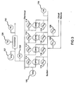
- an exemplary refrigeration system 100 includes a plurality of refrigerated food storage cases 102.
- the refrigeration system 100 includes a plurality of compressors 104 piped together with a common suction manifold 106 and a discharge header 108 all positioned within a compressor rack 110.
- a discharge output 112 of each compressor 102 includes a respective temperature sensor 114.
- An input 116 to the suction manifold 106 includes both a pressure sensor 118 and a temperature sensor 120.
- a discharge outlet 122 of the discharge header 108 includes an associated pressure sensor 124.
- the various sensors are implemented for evaluating maintenance requirements.
- the compressor rack 110 compresses refrigerant vapor that is delivered to a condenser 126 where the refrigerant vapor is liquefied at high pressure.
- Condenser fans 127 are associated with the condenser 126 to enable improved heat transfer from the condenser 126.
- the condenser 126 includes an associated ambient temperature sensor 128 and an outlet pressure sensor 130. This high-pressure liquid refrigerant is delivered to the plurality of refrigeration cases 102 by way of piping 132.
- Each refrigeration case 102 is arranged in separate circuits consisting of a plurality of refrigeration cases 102 that operate within a certain temperature range.
- Figure 1 illustrates four (4) circuits labeled circuit A, circuit B, circuit C and circuit D.
- Each circuit is shown consisting of four (4) refrigeration cases 102. However, those skilled in the art will recognize that any number of circuits, as well as any number of refrigeration cases 102 may be employed within a circuit. As indicated, each circuit will generally operate within a certain temperature range. For example, circuit A may be for frozen food, circuit B may be for dairy, circuit C may be for meat, etc.
- each circuit includes a pressure regulator 134 that acts to control the evaporator pressure and, hence, the temperature of the refrigerated space in the refrigeration cases 102.
- the pressure regulators 134 can be electronically or mechanically controlled.
- Each refrigeration case 102 also includes its own evaporator 136 and its own expansion valve 138 that may be either a mechanical or an electronic valve for controlling the superheat of the refrigerant.
- refrigerant is delivered by piping to the evaporator 136 in each refrigeration case 102.
- the refrigerant passes through the expansion valve 138 where a pressure drop causes the high pressure liquid refrigerant to achieve a lower pressure combination of liquid and vapor.
- the low pressure liquid turns into gas.
- This low pressure gas is delivered to the pressure regulator 134 associated with that particular circuit.
- the pressure is dropped as the gas returns to the compressor rack 110.
- the low pressure gas is again compressed to a high pressure gas, which is delivered to the condenser 126, which creates a high pressure liquid to supply to the expansion valve 138 and start the refrigeration cycle again.
- a main refrigeration controller 140 is used and configured or programmed to control the operation of the refrigeration system 100.
- the refrigeration controller 140 is preferably an Einstein Area Controller offered by CPC, Inc. of Atlanta, Georgia, or any other type of programmable controller that may be programmed, as discussed herein.
- the refrigeration controller 140 controls the bank of compressors 104 in the compressor rack 110, via an input/output module 142.
- the input/output module 142 has relay switches to turn the compressors 104 on an off to provide the desired suction pressure.
- a separate case controller such as a CC-100 case controller, also offered by CPC, Inc. of Atlanta, Georgia may be used to control the superheat of the refrigerant to each refrigeration case 102, via an electronic expansion valve in each refrigeration case 102 by way of a communication network or bus.
- a mechanical expansion valve may be used in place of the separate case controller.
- the main refrigeration controller 140 may be used to configure each separate case controller, also via the communication bus.
- the communication bus may either be a RS-485 communication bus or a LonWorks Echelon bus that enables the main refrigeration controller 140 and the separate case controllers to receive information from each refrigeration case 102.
- Each refrigeration case 102 may have a temperature sensor 146 associated therewith, as shown for circuit B.
- the temperature sensor 146 can be electronically or wirelessly connected to the controller 140 or the expansion valve for the refrigeration case 102.
- Each refrigeration case 102 in the circuit B may have a separate temperature sensor 146 to take average/min/max temperatures or a single temperature sensor 146 in one refrigeration case 102 within circuit B may be used to control each refrigeration case 102 in circuit B because all of the refrigeration cases 102 in a given circuit operate at substantially the same temperature range.
- These temperature inputs are preferably provided to the analog input board 142, which returns the information to the main refrigeration controller 140 via the communication bus.
- Energy sensors 150 are associated with the compressors 104 and the condenser 126 of the refrigeration system 100. The energy sensors 150 monitor energy consumption of their respective components and relay that information to the controller 140.
- the refrigeration controller 140 and case controllers communicates with a remote network or processing center 160.
- the remote processing center 160 can be either in the same location (e.g. food product retailer) as the refrigeration system 100 or can be a centralized processing center that monitors the refrigeration systems of several remote locations.
- the refrigeration controller 140 and case controllers initially communicate with a site-based controller 161 via a serial connection or Ethernet.
- the site-based controller 161 communicates with the processing center 160 via a TCP/IP connection.
- the processing center 160 collects data from the refrigeration controller 140, the case controllers and the various sensors associated with the refrigeration system 100.
- the processing center 160 collects information such as compressor, flow regulator and expansion valve set points from the refrigeration controller 140.
- Data such as pressure and temperature values at various points along the refrigeration circuit are provided by the various sensors via the refrigeration controller 140.
- the software system is a multi-tiered system spanning all three hardware levels. At the local level (i.e., refrigeration controller and case controllers) is the existing controller software and raw I/O data collection and conversion.
- a controller database and the ProAct CB algorithms reside on the site-based controller 161.
- the algorithms manipulate the controller data generating notices, service recommendations, and alarms based on pattern recognition and fuzzy logic.
- this algorithm output (alarms, notices, etc.) is served to a remote network workstation at the processing center 160, where the actual service calls are dispatched and alarms managed.
- the refined data is archived for future analysis and customer access at a client-dedicated website.
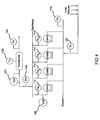
- suction temperature sensors 115 monitor T s of the individual compressors 104 in a rack and a rack current sensor 150 monitors I cmp of a rack.
- the pressure sensor 124 monitors P d and a current sensor 127 monitors I cnd .
- Multiple temperature sensors 129 monitor a return temperature (T c ) for each circuit.
- the present invention provides control and evaluation algorithms in the form of software modules to predict maintenance requirements for the various components in the refrigeration system 100.
- These algorithms include signal conversion and validation, saturated refrigerant properties, watchdog message, recurring notice or alarm message, flood back alert, contactor cycling count, compressor performance, condenser performance, defrost abnormality, case discharge versus product temperature, data pattern recognition, condenser discharge temperature and loss of refrigerant charge. Each is discussed in detail below.
- the algorithms can be processed locally using the refrigeration controller 140 or remotely at the remote processing center 160.
- a signal conversion and validation (SCV) algorithm processes measurement signals from the various sensors.
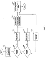
- the SCV algorithm determines the value of a particular signal and up to three different qualities including whether the signal is within a useful range, whether the signal changes over time and/or whether the actual input signal from the sensor is valid.
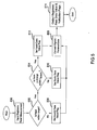
- step 500 the input registers read the measurement signal of a particular sensor.
- step 502 it is determined whether the input signal is within a range that is particular to the type of measurement. If the input signal is within range, the SCV algorithm continues in step 504. If the input signal is not within the range an invalid data range flag is set in step 506 and the SCV algorithm continues in step 508.
- step 504 it is determined whether there is a change ( ⁇ ) in the signal within a threshold time (T thresh ). If there is no change in the signal it is deemed static. In this case, a static data value flag is set in step 510 and the SCV algorithm continues in step 508. If there is a change in the signal a valid data value flag is set in step 512 and the SCV algorithm continues in step 508.
- the signal is converted to provide finished data. More particularly, the signal is generally provided as a voltage.
- the voltage corresponds to a particular value (e.g., temperature, pressure, current, etc.).
- the signal is converted by multiplying the voltage value by a conversion constant (e.g., °C/V, kPa/V, A/V, etc.).
- the output registers pass the data value and validation flags and control ends.
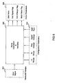
- a measured variable 602 is shown as the input signal.
- the input signal is provided by the instruments or sensors.
- Configuration parameters 604 are provided and include Lo and Hi range values, a time ⁇ , a signal ⁇ and an input type.
- the configuration parameters 604 are specific to each signal and each application.
- Output parameters 606 are output by the SCV block 600 and include the data value, bad signal flag, out of range flag and static value flag. In other words, the output parameters 606 are the finished data and data quality parameters associated with the measured variable.
- the refrigeration property algorithms provide the saturation pressure (P SAT ), density and enthalpy based on temperature.
- the refrigeration property algorithms further provide saturation temperature (T SAT ) based on pressure.
- Each algorithm incorporates thermal property curves for common refrigerant types including, but not limited to, R22, R401a (MP39), R402a (HP80), R404a (HP62), R409a and R507c.
- a refrigerant properties from temperature (RPFT) algorithm is shown.
- step 700 the temperature and refrigerant type are input.
- step 702 it is determined whether the refrigerant is saturated liquid based on the temperature. If the refrigerant is in the saturated liquid state, the RPFT algorithm continues in step 704. If the refrigerant is not in the saturated liquid state, the RPFT algorithm continues in step 706. In step 704, the RPFT algorithm selects the saturated liquid curve from the thermal property curves for the particular refrigerant type and continues in step 708.
- step 706 it is determined whether the refrigerant is in a saturated vapor state. If the refrigerant is in the saturated vapor state, the RPFT algorithm continues in step 710. If the refrigerant is not in the saturated vapor state, the RPFT algorithm continues in step 712. In step 712, the data values are cleared, flags are set and the RPFT algorithm continues in step 714. In step 710, the RPFT algorithm selects the saturated vapor curve from the thermal property curves for the particular refrigerant type and continues in step 708. In step 708, data values for the refrigerant are determined. The data values include pressure, density and enthalpy. In step 714, the RPFT algorithm outputs the data values and flags.
- FIG. 8 a block diagram schematically illustrates an RPFT block 800.
- a measured variable 802 is shown as the temperature.
- the temperature is provided by the instruments or sensors.
- Configuration parameters 804 are provided and include the particular refrigerant type.
- Output parameters 806 are output by the RPFT block 800 and include the pressure, enthalpy, density and data quality flag.
- a refrigerant properties from pressure (RPFP) algorithm is shown.
- step 900 the temperature and refrigerant type are input.
- step 902 it is determined whether the refrigerant is saturated liquid based on the pressure. If the refrigerant is in the saturated liquid state, the RPFP algorithm continues in step 904. If the refrigerant is not in the saturated liquid state, the RPFP algorithm continues in step 906. In step 904, the RPFP algorithm selects the saturated liquid curve from the thermal property curves for the particular refrigerant type and continues in step 908.
- step 906 it is determined whether the refrigerant is in a saturated vapor state. If the refrigerant is in the saturated vapor state, the RPFP algorithm continues in step 910. If the refrigerant is not in the saturated vapor state, the RPFP algorithm continues in step 912. In step 912, the data values are cleared, flags are set and the RPFP algorithm continues in step 914. In step 910, the RPFP algorithm selects the saturated vapor curve from the thermal property curves for the particular refrigerant type and continues in step 908. In step 908, the temperature of the refrigerant is determined. In step 914, the RPFP algorithm outputs the temperature and flags.
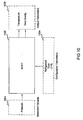
- FIG. 10 a block diagram schematically illustrates an RPFP block 1000.
- a measured variable 1002 is shown as the pressure.
- the pressure is provided by the instruments or sensors.
- Configuration parameters 1004 are provided and include the particular refrigerant type.
- Output parameters 1006 are output by the RPFP block 1000 and include the temperature and data quality flag.
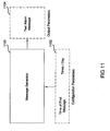
- FIG. 11 a block diagram schematically illustrates the watchdog message algorithm, which includes a message generator 1100, configuration parameters 1102 and output parameters 1104.
- the site-based controller 161 periodically reports its health (i.e., operating condition) to the remainder of the network.
- the site-based controller generates a test message that is periodically broadcast.
- the time and frequency of the message is configured by setting the time of the first message and the number of times per day the test message is to be broadcast.
- Other components of the network e.g., the refrigeration controller 140, the processing center 160 and the case controllers
- periodically receive the test message If the test message is not received by one or more of the other network components, a controller communication fault is indicated.
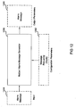
- FIG. 12 a block diagram schematically illustrates the recurring notice or alarm message algorithm.
- the recurring notice or alarm message algorithm monitors the state of signals generated by the various algorithms described herein. Some signals remain in the alarm state for a protracted period of time until the corresponding issue is resolved. As a result, an alarm message that is initially generated as the initial alarm occurs may be overlooked later.
- the recurring notice/alarm message algorithm generates the alarm message at a configured frequency. The alarm message is continuously regenerated until the alarm condition is resolved.
- the recurring notice or alarm message algorithm includes a notice/alarm message generator 1200, configuration parameters 1202, input parameters 1204 and output parameters 1206.
- the configuration parameters 1202 include message frequency.
- the input 1204 includes a notice/alarm message and the output parameters 1206 include a regenerated notice/alarm message.
- the notice/alarm generator 1200 regenerates the input alarm message at the indicated frequency. Once the notice/alarm condition is resolved, the input 1204 will indicate as such and regeneration of the notice/alarm message terminates.
- Liquid refrigerant flood back occurs when liquid refrigerant reverse migrates through the refrigeration system 100 from the evaporator through to the compressor 102.
- the flood back alert algorithm monitors the superheat conditions of the refrigeration circuits A, B, C, D and both the compressor suction/discharge.
- the superheat is filtered through a pattern analyzer and an alarm is generated if the filtered superheat falls outside of a specified range.
- Superheat signals outside of the specified range indicate a flood back event. In the case where multiple flood back events are indicated, a severe flood back alarm is generated.
- the saturated vapor temperature for the compressor suction is calculated from the suction pressure.
- the superheat is calculated for each refrigeration and compressor by subtracting the return temperature from the saturated vapor temperature.
- the superheat for each compressor discharge is calculated by subtracting the compressor discharge temperature from the discharge saturated liquid temperature.
- Figure 13 provides a schematic illustration of a superheat monitor block 1300 that includes an RPFP module 1302 and a pattern analyzer module 1304.
- Measured variables 1306 include temperature and pressure and are input to the superheat monitor 1300.
- Configuration parameters 1308 include refrigerant type and state, data pattern zones and a data sample timer. The refrigerant type and state are input to the RPFP module 1302. The data pattern zones and data sample timer are input to the pattern analyzer 1304.
- the RPFP module 1302 determines the saturated vapor temperature based on the refrigerant type and state and the pressure.
- the superheat monitor 1300 determines the superheat, which is filtered through the pattern analyzer 1304.
- Output parameters 1310 include an alarm message that is generated by the superheat monitor 1300 based on the filtered superheat signal.
- step 1400 P s and T s are measured by the suction temperature and pressure sensors 120,118.
- step 1402 it is determined whether any compressors for the current rack are running. If no compressors are running, the next rack is checked in step 1404. If a compressor is running, the suction saturation temperature (T SSAT ) is determined based on P s . The superheat is determined based on T SSAT and T s in step 1408. The superheat is filtered by the pattern analyzer in step 1410. If appropriate, an alarm message is generated in step 1412 and the algorithm ends. Steps 1402 through 1412 are repeated for each rack and steps 1408 through 1412 are repeated for each refrigeration circuit.
- step 1500 P d and T d are measured by the discharge temperature and pressure sensors.
- step 1502 it is determined whether any compressors for the current rack are running. If no compressors are running, the next rack is checked in step 1504. If a compressor is running, the discharge saturation temperature (T DSAT ) is determined based on P d in step 1506. The superheat is determined based on T DSAT and T d in step 1508. The superheat is filtered by the pattern analyzer in step 1510. If appropriate, an alarm message is generated in step 1512 and the algorithm ends. Steps 1502 through 1512 are repeated for each rack and steps 1508 through 1512 are repeated for each refrigeration circuit.
- the superheat is compared to a threshold value. If the superheat is greater than or equal to the threshold value then a flood back condition exists. In the event of a flood back condition an alert message is generated.
- T SAT is determined by referencing a look-up table using P s and the refrigerant type.
- An alarm value (A) and time delay (t) are also provided as presets and may be user selected.
- An exemplary alarm value is 15° F.
- the suction superheat (SH SUC ) is determined by the difference between T s and T SAT .
- An alarm will be signaled if SH SUC is greater than the alarm value for a time period longer than the time delay. This is governed by the following logic: If SH SUC > A and time > t , then alarm
- the rate of change of T s is monitored. That is to say, the temperature signal from the temperature sensor 118 is monitored over a period of time. The rate of change is compared to a threshold rate of change. If the rate of change of T s is greater than or equal to the threshold rate of change, a flood back condition exists.
- the contactor cycling count algorithm monitors the cycling of the various contacts in the refrigeration system 100.
- the counting mechanism can be one of an internal or an external nature. With respect to internal counting, the refrigeration controller 140 can perform the counting function based on its command signals to operate the various equipment. The refrigeration controller 140 monitors the number of times the particular contact has been cycled (N CYCLE ) for a given load. Alternatively, with respect to external counting, a separate current sensor or auxiliary contact can be used to determine N CYCLE . If N CYCLE per hour for the given load is greater than a threshold number of cycles per hour (N THRESH ), an alarm is initiated. The value of N THRESH is based on the function of the particular contactor.
- N CYCLE can be used to predict when maintenance of the associated equipment or contactor should be scheduled.
- N THRESH is associated with the number of cycles after which maintenance is typically required. Therefore, the alarm indicates maintenance is required on the particular piece of equipment the contact is associated with.
- N CYCLE can be tracked over time to estimate a point in time when it will achieve N THRESH . A predicative alarm is provided indicating a future point in time when maintenance will be required.
- the cycle count for multiple contactors can be monitored.
- a group alarm can be provided to indicate predicted maintenance requirements for a group of equipment.
- the groups include equipment whose N CYCLE count will achieve their respective N THRESH 's within approximately the same time frame. In this manner, the number of maintenance calls is reduced by performing multiple maintenance tasks during a single visit of maintenance personnel.
- a contactor cycle monitoring block 1600 includes a measured variable input 1602 and configuration parameter inputs 1604.
- the contactor cycle monitoring block 1600 processes the measured variable 1602 and the configuration parameters 1604 and generates output parameters 1606.
- the measured variable includes N CYCLE for the particular compressor and the configuration parameters include a cycle rate limit (N CYCRATELlM ) and a cycle maximum (N CYCMAX ).
- the output parameters include a rate exceeded alarm and a maximum exceeded alarm. The rate exceeded alarm is generated when the rate at which the contactor is cycled (N CYCRATE ) exceeds N CYCRATELIM . Similarly, the maximum exceeded alarm is generated when N CYCLE exceeds N CYCMAX .
- FIG. 17 illustrates steps of the contactor cycling count algorithm.
- step 1700 the contactor state (i.e., open or closed) is determined.
- step 1702 it is determined whether a state change has occurred. If a state change has not occurred, the algorithm loops back to step 1700. If a state change has occurred, N CYCLE is incremented in step 1704.
- N CYCRATELIM is determined in step 1708 by dividing N CYCLE by the time over which the closures occurred.
- step 1710 the algorithm determines whether N CYCLE exceeds N CYCMAX . If N CYCLE does not exceed N CYCLEMAX , the algorithm continues in step 1712. If N CYCLE exceeds N CYCMAX , an alarm is generated in step 1714 and the algorithm continues in step 1712. In step 1712, the algorithm determines whether N CYCRATE exceeds N CYCRATELIM . If N CYCRATE does not exceed N CYCRATELIM , the algorithm loops back to step 1700. If N CYCRATE exceeds N CYCRATELIM , an alarm is generated in step 1716 and the algorithm loops back to step 1700.
- the compressor performance algorithm compares a theoretical compressor energy requirement (E THEO ) to an actual measurement of the compressor's energy consumption (E ACT ).
- E THEO is determined based on a model of the compressor.
- E ACT is directly measured from the energy sensors 150.
- a difference between E THEO and E ACT is determined and compared to a threshold value (E THRESH ). If the absolute value of the difference is greater than E THRESH an alarm is initiated indicating a fault in compressor performance.
- compressor fault detection algorithm monitors T d and determines whether the compressor is operating properly based thereon.
- T d reflects the latent heat absorbed in the evaporator, evaporator superheat, suction line heat gain, heat of compression, and compressor motor-generated heat. All of this heat is accumulated at the compressor discharge and must be removed.
- High compressor T d 's result in lubricant breakdown, worn rings, and acid formation, all of which shorten the compressor lifespan. This condition can indicate a variety of problems including, but not limited to damaged compressor valves, partial motor winding shorts, excess compressor wear, piston failure and high compression ratios.
- High compression ratios can be caused by either low P s , high head pressure, or a combination of the two.
- T DSAT discharge saturation temperature
- SH discharge saturation temperature
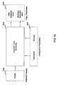
- a compressor performance monitor block 1800 generates an output parameter 1802 based on measured variables 1804 and configuration parameters 1806.
- the output parameter 1802 includes an alarm and the measured variable includes T d and P d .
- the configuration parameters include refrigerant type and state and data pattern zones and a data sample timer.
- the compressor performance monitor block 1800 determines SH and processes SH through the data pattern analyzer and generates the alarm if required.
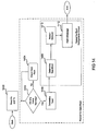
- step 1900 P d and T d are measured by the discharge temperature and pressure sensors.
- step 1902 it is determined whether the current rack is running. If the current rack is not running, the algorithm moves to the next rack in step 1904.
- step 1906 and 1908 it is determined whether each compressor in the rack is running.
- T DSAT is determined for the running compressor based on P d .
- the superheat is determined based on T DSAT and T d in step 1912.
- the superheat is filtered by the pattern analyzer in step 1914. If appropriate, an alarm message is generated in step 1916 and the algorithm loops back to step 1904. Steps 1902 through 1916 are repeated for each rack and steps 1906 through 1916 are repeated for each refrigeration circuit.
- the compressor fault detection algorithm compares the actual T d to a calculated discharge temperature (T dcalc ).
- T d is measured by the temperature sensors 114 associated with the discharge of each compressor 102. Measurements are taken at approximately 10 second intervals while the compressors 102 are running.
- T dcalc is calculated as a function of the refrigerant type, P d , suction pressure (P s ) and suction temperature (T s ), each of which are measured by the associated sensors described above.
- An alarm value (A) and time delay (t) are also provided as presets and may be user selected. An alarm is signaled if the difference between the actual and calculated discharge temperature is greater than the alarm value for a time period longer than the time delay. This is governed by the following logic: If T d - T dcalc > A and time > t , then alarm
- the condenser performance algorithm is provided to determine whether the condenser 126 is dirty, which would result in a loss of energy efficiency or more serious system problems.
- Trend data is analyzed over a specified time period (e.g., several days). More specifically, the average difference between the ambient temperature (T a ) and the condensing temperature (T COND ) is determined over the time period. If the average difference is greater than a threshold (T THRESH ) (e.g., 25°F) a dirty condenser situation is indicated and a maintenance alarm is initiated.
- T THRESH e.g. 25°F
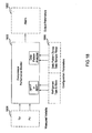
- a condenser performance monitor block 2000 includes an RPFP module 2002 and a pattern analyzer module 2004.
- the condenser performance monitor block 2000 receives measured variables 2006 and configuration parameters 2008 and generates output parameters 2010 based thereon.
- the measured variables include T a , P c , I cmp and a condenser load (I cnd ).
- the configuration parameters 2008 include refrigerant type and state, data pattern zones and a data sampler timer.
- the output parameters 2010 include an alarm message.
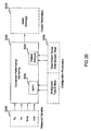
- T a , P c , I cmp and I cnd are all measured by their respective sensors in step 2100.
- T c is determined based on P c using RPFP, as discussed in detail above.
- U is processed through the pattern analyzer and an alarm maybe generated in step 2108 based on the results. As U varies from ideal, condenser performance may be impaired and an alarm message will be generated.
- the defrost abnormality algorithm learns the behavior of defrost activity in the refrigeration circuits A, B, C, D. The learned or average defrost behavior is compared to current or past defrost conditions. More specifically, the defrost time (t DEF ), maximum defrost time (t DEFMAX ) and defrost termination temperature (T TERM ) are monitored. If t DEF achieves t DEFMAX for a number of consecutive defrost cycles (N DEF ) (e.g., 5 cycles) and the particular case or circuit is set to terminate defrost at T TERM , an abnormal defrost situation is indicated. An alarm is initiated accordingly. The defrost abnormality algorithm also monitors T TERM across cases within a circuit to isolate cases having the highest T TERM .
- N DEF consecutive defrost cycles
- the case discharge versus product temperature algorithm compares the air discharge temperature (T DISCHARGE ) to the case's set point temperature (T SETPOINT ) and the product temperature (T PROD ) to T DISCHARGE .
- the case temperature (T CASE ) is also monitored. If T DISCHARGE is equal to T SETPOINT , and T PROD is greater than T CASE plus a tolerance temperature (T TOL ) a problem with the case is indicated. An alarm is initiated accordingly.
- Refrigerant level within the refrigeration system 100 is a function of refrigeration load, ambient temperatures, defrost status, heat reclaim status and refrigerant charge.
- a reservoir level indicator (not shown) reads accurately when the system is running and stable and it varies with the cooling load. When the system is turned off, refrigerant pools in the coldest parts of the system and the level indicator may provide a false reading.
- the refrigerant loss detection algorithm determines whether there is leakage in the refrigeration system 100.
- the liquid refrigerant level in an optional receiver (not shown) is monitored. The receiver would be disposed between the condenser 126 and the individual circuits A, B, C, D. If the liquid refrigerant level in the receiver drops below a threshold level, a loss of refrigerant is indicated and an alarm is initiated.
- the data pattern recognition algorithm monitors inputs such as T CASE , T PROD , P s and P d .
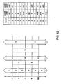
- the algorithm includes a data table (see Figure 22 ) having multiple bands whose upper and lower limits are defined by configuration parameters. A particular input is measured at a configured frequency (e.g., every minute, hour, day, etc.). as the input value changes, the algorithm determines within which band the value lies and increments a counter for that band. After the input has been monitored for a specified time period (e.g., a day, a week, a month, etc.) alarms are generated based on the band populations.
- a specified time period e.g., a day, a week, a month, etc.
- the bands are defined by various boundaries including a high positive (PP) boundary, a positive (P) boundary, a zero (Z) boundary, a minus (M) boundary and a high minus (MM) boundary.
- the number of bands and the boundaries thereof are determined based on the particular refrigeration system operating parameter to be monitored. For each reading a corresponding band is populated. If the population of a particular band exceeds an alarm limit, a corresponding alarm is generated.
- a pattern analyzer block 2500 receives measured variables 2502, configuration parameters 2504 and generates output parameters 2506 based thereon.
- the measured variables 2502 include an input (e.g., T CASE , T PROD, P s and P d ).
- the configuration parameters 2504 include a data sample timer and data pattern zone information.
- the data sample timer includes a duration, an interval and a frequency.
- the data pattern zone information defines the bands and which bands are to be enabled.
- the data pattern zone information provides the boundary values (e.g., PP) band enablement (e.g., PPen), band value (e.g., PPband) and alarm limit (e.g., PPpct).
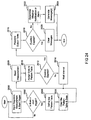
- step 2602 the algorithm determines whether the start trigger is present. If the start trigger is not present, the algorithm loops back to step 2600. If the start trigger is present, the pattern table is defined in step 2604 based on the data pattern bands. In step 2606, the pattern table is cleared. In step 2608, the measurement is read and the measurement data is assigned to the pattern table in step 2610.
- step 2612 the algorithm determines whether the duration has expired. If the duration has not yet expired, the algorithm waits for the defined interval in step 2614 and loops back to step 2608. If the duration has expired, the algorithm populates the output table in step 2616. In step 2618, the algorithm determines whether the results are normal. In other words, the algorithm determines whether the population of a each band is below the alarm limit for that band. If the results are normal, messages are cleared in step 2620 and the algorithm ends. If the results are not normal, the algorithm determines whether to generate a notification or an alarm in step 2622. In step 2624, the alarm or notification message(s) is/are generated and the algorithm ends.
Landscapes
- Engineering & Computer Science (AREA)
- Physics & Mathematics (AREA)
- Mechanical Engineering (AREA)
- Thermal Sciences (AREA)
- General Engineering & Computer Science (AREA)
- Air Conditioning Control Device (AREA)
- Telephonic Communication Services (AREA)
- Devices That Are Associated With Refrigeration Equipment (AREA)
Claims (26)
- Système (100) de surveillance d'un système de réfrigération à distance, le système comprenant :une pluralité de capteurs (114, 115, 120, 124, 127, 128, 129, 130, 146, 150) qui surveillent des paramètres des composants dudit système de réfrigération ;un réseau de communication (140, 161) qui transfère les signaux générés par chacun de ladite pluralité de capteurs ; etun centre de gestion (160) qui reçoit lesdits signaux de la part dudit réseau de communication, ledit centre de gestion traitant lesdits signaux afin de déterminer une condition de fonctionnement d'au moins l'un desdits composants et générant une alarme sur la base de ladite condition de fonctionnement ;le système (100) comprenant en outre :un capteur de température ambiante de condensateur (128) qui génère un signal de température ambiante ;un capteur de pression de condensateur (130) qui génère un signal de pression ;un capteur de courant de compresseur (150) qui génère un signal de courant de compresseur ; etun capteur de courant de condensateur (127) qui génère un signal de courant de condensateur ;dans lequel ledit centre de gestion (160) détermine une condition de fonctionnement dudit condensateur (126) sur la base dudit signal de température ambiante, dudit signal de pression, dudit signal de courant de compresseur et dudit signal de courant de condensateur.
- Système (100) selon la revendication 1, dans lequel ledit centre de gestion évalue chacun desdits signaux afin de déterminer si chacun desdits signaux se trouve dans des limites utiles, afin de déterminer si chacun desdits signaux est dynamique, et afin de déterminer si chacun desdits signaux est valide.
- Système (100) selon la revendication 1, qui comprend en outre un capteur de température (114, 115) qui surveille une température d'un réfrigérant qui circule dans ledit système de réfrigération et qui génère un signal de température.
- Système (100) selon la revendication 3, dans lequel ledit centre de gestion (160) calcule une pression, une densité et une enthalpie dudit réfrigérant sur la base de ladite température et sur la base du fait que ledit réfrigérant se trouve dans l'une d'une phase liquide saturée ou d'une phase vapeur saturée.
- Système (100) selon la revendication 1, qui comprend en outre un capteur de pression (118, 124) qui surveille une pression d'un réfrigérant qui circule dans ledit système de réfrigération et qui génère un signal de pression.
- Système (100) selon la revendication 5, dans lequel ledit centre de gestion (160) calcule une température, une densité et une enthalpie dudit réfrigérant sur la base de ladite pression et sur la base du fait que ledit réfrigérant se trouve dans l'une d'une phase liquide saturée ou d'une phase vapeur saturée.
- Système (100) selon la revendication 1, qui comprend en outre :un capteur de température (115) qui surveille une température d'un réfrigérant au niveau du côté aspiration d'un compresseur (104) dudit système de réfrigération, et qui génère un signal de température ; etun capteur de pression (118) qui surveille une pression d'un réfrigérant au niveau dudit côté aspiration dudit compresseur (104) et qui génère un signal de pression ;dans lequel ledit centre de gestion (106) détermine la survenance d'un évènement de reflux sur la base dudit signal de température et dudit signal de pression.
- Système (100) selon la revendication 7, dans lequel ledit centre de gestion (160) détermine une température de surchauffe dudit réfrigérant sur la base dudit signal de température et dudit signal de pression et observe une évolution de ladite surchauffe sur une période de temps afin de déterminer si ledit évènement de reflux s'est produit ou non.
- Système (100) selon la revendication 1, qui comprend en outre :un capteur de température (114) qui surveille une température d'un réfrigérant au niveau d'un côté décharge d'un compresseur (104) dudit système de réfrigération, et qui génère un signal de température ; etun capteur de pression (124) qui surveille une pression d'un réfrigérant au niveau dudit côté décharge dudit compresseur (104), et qui génère un signal de pression ;dans lequel ledit centre de gestion (160) détermine la survenance d'un évènement de reflux sur la base dudit signal de température et dudit signal de pression.
- Système (100) selon la revendication 9, dans lequel ledit centre de gestion (160) détermine une température de surchauffe dudit réfrigérant sur la base dudit signal de température et dudit signal de pression, et observe l'évolution de ladite surchauffe sur une période de temps afin de déterminer si ledit évènement de reflux s'est produit ou non.
- Système (100) selon la revendication 1, qui comprend en outre un contacteur associé à l'un desdits composants et qui est cyclé entre une position ouverte et une position fermée afin de faire fonctionner sélectivement ledit composant.
- Système (100) selon la revendication 11, dans lequel ledit centre de gestion (160) surveille le cyclage dudit contacteur et génère une alarme lorsque l'un d'une vitesse de cyclage et d'un nombre maximum de cycles est dépassé.
- Système (100) selon la revendication 1, dans lequel ledit centre de gestion (160) détermine une consommation d'énergie dudit condensateur (126), observe ladite consommation d'énergie sur une période de temps, et génère sélectivement une alarme sur la base d'une évolution de ladite consommation d'énergie.
- Procédé de surveillance d'un système de réfrigération (100) au niveau d'un emplacement distant, qui comprend les étapes qui consistent à :générer des signaux à partir d'une pluralité de capteurs (114, 115, 120, 124, 127, 128, 129, 130, 146, 150) qui surveillent des paramètres des composants dudit système de réfrigération (100) ;transférer les signaux générés par chacun de ladite pluralité de capteurs sur un réseau de communication (140, 161) ;traiter lesdits signaux afin de déterminer une condition de fonctionnement d'au moins l'un desdits composants ; etgénérer une alarme sur la base de ladite condition de fonctionnement ;le procédé comprenant en outre :la génération d'un signal de température ambiante sur la base d'une température ambiante d'un condensateur (126) ;générer un signal de pression sur la base d'une pression de condensateur ;générer un signal de courant de compresseur sur la base d'un courant de compresseur ;générer un signal de courant de condensateur sur la base d'un courant de condensateur ; etdéterminer une condition de fonctionnement dudit condensateur sur la base dudit signal de température ambiante, dudit signal de pression, dudit signal de courant de compresseur, et dudit signal de courant de condensateur.
- Procédé selon la revendication 14, qui comprend en outre l'évaluation de chacun desdits signaux afin de déterminer si chacun desdits signaux se trouve dans des limites utiles, afin de déterminer si chacun desdits signaux est dynamique, et afin de déterminer si chacun desdits signaux est valide.
- Procédé selon la revendication 14, qui comprend en outre :la surveillance d'une température d'un réfrigérant qui circule dans ledit système de réfrigération ; etla génération d'un signal de température sur la base de ladite température.
- Procédé selon la revendication 16, qui comprend en outre le calcul d'une pression, d'une densité et d'une enthalpie dudit réfrigérant sur la base de ladite température, et sur la base du fait que ledit réfrigérant se trouve dans l'une d'une phase liquide saturée ou d'une phase vapeur saturée.
- Procédé selon la revendication 14, qui comprend en outre :la surveillance d'une pression d'un réfrigérant qui circule dans ledit système de réfrigération (100) ; etla génération d'un signal de pression sur la base de ladite pression.
- Procédé selon la revendication 18, qui comprend en outre le calcul d'une température, d'une densité et d'une enthalpie dudit réfrigérant sur la base de ladite pression et sur la base du fait que ledit réfrigérant se trouve dans l'une d'une phase liquide saturée ou d'une phase vapeur saturée.
- Procédé selon la revendication 14, qui comprend en outre :la surveillance d'une température d'un réfrigérant au niveau du côté aspiration d'un compresseur (104) dudit système de réfrigération (100) ;la génération d'un signal de température sur la base de ladite température ;la surveillance d'une pression d'un réfrigérant au niveau dudit côté aspiration dudit compresseur (104) ;la génération d'un signal de pression sur la base de ladite pression ; etla détermination de la survenance d'un évènement de reflux sur la base dudit signal de température et dudit signal de pression.
- Procédé selon la revendication 20, qui comprend en outre :la détermination d'une température de surchauffe dudit réfrigérant sur la base dudit signal de température et dudit signal de pression ; etl'observation d'une évolution de ladite surchauffe sur une période de temps afin de déterminer si ledit évènement de reflux s'est produit ou non.
- Procédé selon la revendication 14, qui comprend en outre :la surveillance d'une température d'un réfrigérant au niveau du côté décharge d'un compresseur (104) dudit système de réfrigération (100) ;la génération d'un signal de température sur la base de ladite température ;la surveillance d'une pression d'un réfrigérant au niveau dudit côté décharge dudit compresseur (104) ;la génération d'un signal de pression sur la base de ladite pression ; etla détermination de la survenance d'un évènement de reflux sur la base dudit signal de température et dudit signal de pression.
- Procédé selon la revendication 22, qui comprend en outre :la détermination d'une température de surchauffe dudit réfrigérant sur la base dudit signal de température et dudit signal de pression ; etl'observation d'une évolution de ladite surchauffe sur une période de temps afin de déterminer si ledit évènement de reflux s'est produit ou non.
- Procédé selon la revendication 14, qui comprend en outre le cyclage d'un contacteur associé à l'un desdits composants entre une position ouverte et une position fermée afin de faire fonctionner sélectivement ledit composant.
- Procédé selon la revendication 24, qui comprend en outre :la surveillance dudit cyclage dudit contacteur ; etla génération d'une alarme lorsque l'un d'une vitesse de cyclage et d'un nombre maximum de cycles est dépassé.
- Procédé selon la revendication 14, qui comprend en outre :la détermination d'une consommation d'énergie dudit condensateur ;l'observation de ladite consommation d'énergie sur une période de temps ; etla génération sélective d'une alarme sur la base d'une évolution de ladite consommation d'énergie.
Applications Claiming Priority (3)
| Application Number | Priority Date | Filing Date | Title |
|---|---|---|---|
| US46663703P | 2003-04-30 | 2003-04-30 | |
| US10/833,259 US7490477B2 (en) | 2003-04-30 | 2004-04-27 | System and method for monitoring a condenser of a refrigeration system |
| PCT/US2004/013384 WO2004099683A2 (fr) | 2003-04-30 | 2004-04-29 | Maintenance predictive et equipement de controle de systeme de refrigeration |
Publications (3)
| Publication Number | Publication Date |
|---|---|
| EP1618345A2 EP1618345A2 (fr) | 2006-01-25 |
| EP1618345A4 EP1618345A4 (fr) | 2011-12-14 |
| EP1618345B1 true EP1618345B1 (fr) | 2014-07-16 |
Family
ID=33513957
Family Applications (1)
| Application Number | Title | Priority Date | Filing Date |
|---|---|---|---|
| EP04760640.5A Expired - Lifetime EP1618345B1 (fr) | 2003-04-30 | 2004-04-29 | Maintenance predictive et equipement de controle de systeme de refrigeration |
Country Status (6)
| Country | Link |
|---|---|
| US (2) | US7490477B2 (fr) |
| EP (1) | EP1618345B1 (fr) |
| CN (1) | CN1781006B (fr) |
| AU (1) | AU2004236695B8 (fr) |
| CA (1) | CA2499201C (fr) |
| WO (1) | WO2004099683A2 (fr) |
Cited By (1)
| Publication number | Priority date | Publication date | Assignee | Title |
|---|---|---|---|---|
| US10088202B2 (en) | 2009-10-23 | 2018-10-02 | Carrier Corporation | Refrigerant vapor compression system operation |
Families Citing this family (93)
| Publication number | Priority date | Publication date | Assignee | Title |
|---|---|---|---|---|
| US6505475B1 (en) | 1999-08-20 | 2003-01-14 | Hudson Technologies Inc. | Method and apparatus for measuring and improving efficiency in refrigeration systems |
| US6668240B2 (en) * | 2001-05-03 | 2003-12-23 | Emerson Retail Services Inc. | Food quality and safety model for refrigerated food |
| US6892546B2 (en) | 2001-05-03 | 2005-05-17 | Emerson Retail Services, Inc. | System for remote refrigeration monitoring and diagnostics |
| US6889173B2 (en) * | 2002-10-31 | 2005-05-03 | Emerson Retail Services Inc. | System for monitoring optimal equipment operating parameters |
| CN100489419C (zh) | 2003-08-25 | 2009-05-20 | 计算机程序控制公司 | 制冷系统和方法 |
| US20050177282A1 (en) * | 2004-01-16 | 2005-08-11 | Mason Paul L.Ii | Energy saving vending machine and control |
| US7412842B2 (en) | 2004-04-27 | 2008-08-19 | Emerson Climate Technologies, Inc. | Compressor diagnostic and protection system |
| US7424343B2 (en) | 2004-08-11 | 2008-09-09 | Lawrence Kates | Method and apparatus for load reduction in an electric power system |
| US7275377B2 (en) * | 2004-08-11 | 2007-10-02 | Lawrence Kates | Method and apparatus for monitoring refrigerant-cycle systems |
| EP1781996A2 (fr) | 2004-08-11 | 2007-05-09 | Lawrence Kates | Procede et dispositif pour le controle de systemes de cycle de refrigeration |
| US7621141B2 (en) * | 2004-09-22 | 2009-11-24 | York International Corporation | Two-zone fuzzy logic liquid level control |
| ATE553422T1 (de) * | 2005-02-21 | 2012-04-15 | Computer Process Controls Inc | Kontroll- und beobachtungssystem für unternehmen |
| US8150720B2 (en) | 2005-08-29 | 2012-04-03 | Emerson Retail Services, Inc. | Dispatch management model |
| DE602005012099D1 (de) * | 2005-09-07 | 2009-02-12 | Whirlpool Co | Verfahren zum Schätzen der Temperatur von Nahrungsmitteln in einem Innenraum von einem Kühlschrank und mit diesem Verfahren betriebener Kühlschrank |
| ITMI20051789A1 (it) * | 2005-09-27 | 2007-03-28 | Finanziaria Unterland S P A | Impianto frigorifero di conservazione particolarmente per uso domestico |
| US7665315B2 (en) | 2005-10-21 | 2010-02-23 | Emerson Retail Services, Inc. | Proofing a refrigeration system operating state |
| US7752853B2 (en) * | 2005-10-21 | 2010-07-13 | Emerson Retail Services, Inc. | Monitoring refrigerant in a refrigeration system |
| US7596959B2 (en) | 2005-10-21 | 2009-10-06 | Emerson Retail Services, Inc. | Monitoring compressor performance in a refrigeration system |
| US7594407B2 (en) | 2005-10-21 | 2009-09-29 | Emerson Climate Technologies, Inc. | Monitoring refrigerant in a refrigeration system |
| US7752854B2 (en) * | 2005-10-21 | 2010-07-13 | Emerson Retail Services, Inc. | Monitoring a condenser in a refrigeration system |
| AT503292B1 (de) * | 2006-04-21 | 2007-09-15 | Thomas Brausteiner | Alarmvorrichtung |
| US8590325B2 (en) | 2006-07-19 | 2013-11-26 | Emerson Climate Technologies, Inc. | Protection and diagnostic module for a refrigeration system |
| US9103575B2 (en) * | 2006-08-01 | 2015-08-11 | Carrier Corporation | Operation and control of tandem compressors and reheat function |
| US20080216494A1 (en) | 2006-09-07 | 2008-09-11 | Pham Hung M | Compressor data module |
| US20090037142A1 (en) | 2007-07-30 | 2009-02-05 | Lawrence Kates | Portable method and apparatus for monitoring refrigerant-cycle systems |
| US8393169B2 (en) | 2007-09-19 | 2013-03-12 | Emerson Climate Technologies, Inc. | Refrigeration monitoring system and method |
| US7895003B2 (en) | 2007-10-05 | 2011-02-22 | Emerson Climate Technologies, Inc. | Vibration protection in a variable speed compressor |
| US8459053B2 (en) | 2007-10-08 | 2013-06-11 | Emerson Climate Technologies, Inc. | Variable speed compressor protection system and method |
| US8418483B2 (en) | 2007-10-08 | 2013-04-16 | Emerson Climate Technologies, Inc. | System and method for calculating parameters for a refrigeration system with a variable speed compressor |
| US9541907B2 (en) | 2007-10-08 | 2017-01-10 | Emerson Climate Technologies, Inc. | System and method for calibrating parameters for a refrigeration system with a variable speed compressor |
| US8539786B2 (en) | 2007-10-08 | 2013-09-24 | Emerson Climate Technologies, Inc. | System and method for monitoring overheat of a compressor |
| US9140728B2 (en) | 2007-11-02 | 2015-09-22 | Emerson Climate Technologies, Inc. | Compressor sensor module |
| US8160827B2 (en) | 2007-11-02 | 2012-04-17 | Emerson Climate Technologies, Inc. | Compressor sensor module |
| KR101470631B1 (ko) * | 2008-03-12 | 2014-12-08 | 엘지전자 주식회사 | 공기 조화기의 제어방법 |
| US8322151B1 (en) | 2008-08-13 | 2012-12-04 | Demand Side Environmental, LLC | Systems and methods for gathering data from and diagnosing the status of an air conditioner |
| MX2011012546A (es) | 2009-05-29 | 2012-10-03 | Emerson Retail Services Inc | Sistema y metodo para monitorear y evaluar modificaciones de parametros operativos de equipo. |
| US8301403B2 (en) * | 2009-09-14 | 2012-10-30 | Weick Brian K | Hand held refrigeration gauge |
| US10055699B2 (en) * | 2009-11-03 | 2018-08-21 | Automation Creations, Inc. | System for supermarket energy management |
| EP2681497A4 (fr) | 2011-02-28 | 2017-05-31 | Emerson Electric Co. | Solutions de contrôle et de diagnostic d'un système hvac destinées à des habitations |
| US9970696B2 (en) * | 2011-07-20 | 2018-05-15 | Thermo King Corporation | Defrost for transcritical vapor compression system |
| US8964338B2 (en) | 2012-01-11 | 2015-02-24 | Emerson Climate Technologies, Inc. | System and method for compressor motor protection |
| SG11201404722YA (en) | 2012-02-10 | 2014-10-30 | Carrier Corp | Method for detection of loss of refrigerant |
| US9513043B2 (en) | 2012-06-25 | 2016-12-06 | Whirlpool Corporation | Fault detection and diagnosis for refrigerator from compressor sensor |
| US9480177B2 (en) | 2012-07-27 | 2016-10-25 | Emerson Climate Technologies, Inc. | Compressor protection module |
| US9310439B2 (en) | 2012-09-25 | 2016-04-12 | Emerson Climate Technologies, Inc. | Compressor having a control and diagnostic module |
| ITMI20121677A1 (it) * | 2012-10-08 | 2014-04-09 | Dixell S R L Societa Unipersonale | Sistema di controllo per apparati e sistemi refrigerati con avanzate funzioni di risparmio energetico |
| EP2941604B1 (fr) * | 2012-12-27 | 2018-09-05 | Thermo King Corporation | Procédé permettant de réduire l'engorgement de liquide dans une unité de réfrigération de transport |
| US9803902B2 (en) | 2013-03-15 | 2017-10-31 | Emerson Climate Technologies, Inc. | System for refrigerant charge verification using two condenser coil temperatures |
| US9234686B2 (en) | 2013-03-15 | 2016-01-12 | Energy Recovery Systems Inc. | User control interface for heat transfer system |
| WO2014144446A1 (fr) | 2013-03-15 | 2014-09-18 | Emerson Electric Co. | Diagnostic et système de télésurveillance de chauffage, de ventilation et de climatisation |
| US20140260380A1 (en) * | 2013-03-15 | 2014-09-18 | Energy Recovery Systems Inc. | Compressor control for heat transfer system |
| US9016074B2 (en) | 2013-03-15 | 2015-04-28 | Energy Recovery Systems Inc. | Energy exchange system and method |
| US10260775B2 (en) | 2013-03-15 | 2019-04-16 | Green Matters Technologies Inc. | Retrofit hot water system and method |
| US9551504B2 (en) | 2013-03-15 | 2017-01-24 | Emerson Electric Co. | HVAC system remote monitoring and diagnosis |
| CA2908362C (fr) | 2013-04-05 | 2018-01-16 | Fadi M. Alsaleem | Systeme de pompe a chaleur a diagnostique de charge de fluide refrigerant |
| US10451341B2 (en) | 2013-08-29 | 2019-10-22 | Maersk Line A/S | Computer-implemented method of monitoring the operation of a cargo shipping reefer container |
| US9696073B2 (en) | 2014-12-16 | 2017-07-04 | Johnson Controls Technology Company | Fault detection and diagnostic system for a refrigeration circuit |
| US9644873B2 (en) * | 2015-01-29 | 2017-05-09 | Timothy Teckman | Method and apparatus for refrigeration system energy signature capture |
| US9562710B2 (en) | 2015-04-27 | 2017-02-07 | Emerson Climate Technologies, Inc. | Diagnostics for variable-capacity compressor control systems and methods |
| US9709311B2 (en) | 2015-04-27 | 2017-07-18 | Emerson Climate Technologies, Inc. | System and method of controlling a variable-capacity compressor |
| US10197319B2 (en) | 2015-04-27 | 2019-02-05 | Emerson Climate Technologies, Inc. | System and method of controlling a variable-capacity compressor |
| US10240836B2 (en) | 2015-06-30 | 2019-03-26 | Emerson Climate Technologies Retail Solutions, Inc. | Energy management for refrigeration systems |
| US11009250B2 (en) | 2015-06-30 | 2021-05-18 | Emerson Climate Technologies Retail Solutions, Inc. | Maintenance and diagnostics for refrigeration systems |
| CN107735575B (zh) * | 2015-07-06 | 2019-10-18 | 江森自控科技公司 | 用于多级离心压缩机的容量控制系统和方法 |
| US10168067B2 (en) * | 2015-09-22 | 2019-01-01 | Lennox Industries Inc. | Detecting and handling a blocked condition in the coil |
| US10578328B2 (en) * | 2016-02-11 | 2020-03-03 | Vertiv Corporation | Systems and methods for detecting degradation of a component in an air conditioning system |
| US10408517B2 (en) | 2016-03-16 | 2019-09-10 | Emerson Climate Technologies, Inc. | System and method of controlling a variable-capacity compressor and a variable speed fan using a two-stage thermostat |
| JP6723799B2 (ja) * | 2016-04-08 | 2020-07-15 | 三菱電機ビルテクノサービス株式会社 | 空調吹き出し温度推定装置及びプログラム |
| US10760814B2 (en) | 2016-05-27 | 2020-09-01 | Emerson Climate Technologies, Inc. | Variable-capacity compressor controller with two-wire configuration |
| CN106196701B (zh) * | 2016-06-28 | 2019-07-23 | 福建雪人股份有限公司 | 用于向工地供冷的制冷系统 |
| US10310482B2 (en) * | 2016-07-15 | 2019-06-04 | Honeywell International Inc. | Refrigeration rack monitor |
| US10627146B2 (en) * | 2016-10-17 | 2020-04-21 | Emerson Climate Technologies, Inc. | Liquid slugging detection and protection |
| CN107401865A (zh) * | 2017-07-14 | 2017-11-28 | 成都冷云能源科技有限公司 | 一种生成制冷或制热设备监测或控制参数的系统和方法 |
| CN107289697A (zh) * | 2017-07-14 | 2017-10-24 | 成都冷云能源科技有限公司 | 一种用于建立制冷或制热设备监测或控制模型的系统和方法 |
| CN107388659A (zh) * | 2017-07-14 | 2017-11-24 | 成都冷云能源科技有限公司 | 一种基于物联网的制冷或制热设备管理系统及方法 |
| US10941980B2 (en) | 2017-09-06 | 2021-03-09 | International Business Machines Corporation | Predictive maintenance of refrigeration cases |
| EP3745055B1 (fr) * | 2018-01-25 | 2024-03-06 | Mitsubishi Electric Corporation | Système d'analyse d'état et dispositif d'analyse d'état |
| US10704797B2 (en) | 2018-03-01 | 2020-07-07 | Johnson Controls Technology Company | Sensor management systems for HVAC systems |
| WO2019187003A1 (fr) * | 2018-03-30 | 2019-10-03 | 日本電気株式会社 | Dispositif d'estimation d'état, procédé, et support d'enregistrement de programme |
| US11346570B2 (en) | 2018-11-29 | 2022-05-31 | Daikin Industries, Ltd. | Refrigerant leakage determination system and refrigeration cycle apparatus |
| US11206743B2 (en) | 2019-07-25 | 2021-12-21 | Emerson Climate Technolgies, Inc. | Electronics enclosure with heat-transfer element |
| DE102019211503A1 (de) * | 2019-08-01 | 2021-02-04 | Robert Bosch Gmbh | Verfahren zum Betreiben eines Kältemittelkompressors und Kältemittelkompressorsystem |
| DE102020121260A1 (de) * | 2020-08-12 | 2022-02-17 | Bitzer Kühlmaschinenbau Gmbh | Verfahren zur Betriebszustandsermittlung eines Kältemittelverdichters/-expanders |
| US12613504B2 (en) | 2021-02-02 | 2026-04-28 | True Manufacturing Co., Inc. | Systems and methods for managing leased appliances |
| US11936489B2 (en) | 2021-02-02 | 2024-03-19 | True Manufacturing Co., Inc. | Systems, methods, and appliances that enable regional control of refrigeration appliances |
| US11711259B2 (en) | 2021-02-12 | 2023-07-25 | Zebra Technologies Corporation | Method, system and apparatus for detecting device malfunctions |
| IT202100003485A1 (it) * | 2021-02-16 | 2022-08-16 | Carel Ind Spa | Procedimento per la diagnosi di un'operazione di sbrinamento in un sistema frigorifero |
| DE102021211280B4 (de) | 2021-10-06 | 2023-05-04 | Glen Dimplex Deutschland Gmbh | Verfahren sowie Vorrichtung zur Überwachung einer Kältemittel-Anlage |
| DE102021006682A1 (de) | 2021-10-06 | 2023-06-22 | Glen Dimplex Deutschland Gmbh | Verfahren sowie Vorrichtung zur Überwachung einer Kältemittel-Anlage |
| US12379144B2 (en) | 2022-03-10 | 2025-08-05 | True Manufacturing Co., Inc. | Ice maker and system and method for monitoring water filter of the ice maker |
| CN119585578A (zh) | 2022-07-28 | 2025-03-07 | 真实制造有限公司 | 用于制冷设备的资产管理和物联网装置 |
| US12523404B2 (en) | 2023-01-25 | 2026-01-13 | Copeland Lp | Retrofit for fan control in refrigerated cases |
| CN119595344B (zh) * | 2025-01-24 | 2025-09-23 | 内蒙古蒙牛乳业(集团)股份有限公司 | 发酵乳制品降温系统测试方法、装置、电子设备及存储介质 |
Family Cites Families (35)
| Publication number | Priority date | Publication date | Assignee | Title |
|---|---|---|---|---|
| US4325223A (en) | 1981-03-16 | 1982-04-20 | Cantley Robert J | Energy management system for refrigeration systems |
| US4510576A (en) | 1982-07-26 | 1985-04-09 | Honeywell Inc. | Specific coefficient of performance measuring device |
| GB2142130B (en) * | 1982-11-18 | 1987-03-18 | Evans Cooling Ass | Boiling liquid cooling system for internal combustion engines |
| SE439063B (sv) | 1983-06-02 | 1985-05-28 | Henrik Sven Enstrom | Forfarande och anordning for provning och prestandaovervakning vid vermepumpar och kylanleggningar |
| JPS62116844A (ja) | 1985-11-13 | 1987-05-28 | Matsushita Seiko Co Ltd | 空気調和機の中央監視制御システム |
| US4939909A (en) | 1986-04-09 | 1990-07-10 | Sanyo Electric Co., Ltd. | Control apparatus for air conditioner |
| US4768346A (en) | 1987-08-26 | 1988-09-06 | Honeywell Inc. | Determining the coefficient of performance of a refrigeration system |
| US4841734A (en) * | 1987-11-12 | 1989-06-27 | Eaton Corporation | Indicating refrigerant liquid saturation point |
| US5181389A (en) | 1992-04-26 | 1993-01-26 | Thermo King Corporation | Methods and apparatus for monitoring the operation of a transport refrigeration system |
| US5209076A (en) | 1992-06-05 | 1993-05-11 | Izon, Inc. | Control system for preventing compressor damage in a refrigeration system |
| US5369958A (en) * | 1992-10-15 | 1994-12-06 | Mitsubishi Denki Kabushiki Kaisha | Air conditioner |
| US5586446A (en) | 1993-11-16 | 1996-12-24 | Hoshizaki Denki Kabushiki Kaisha | Monitoring system for ice making machine |
| US5460006A (en) | 1993-11-16 | 1995-10-24 | Hoshizaki Denki Kabushiki Kaisha | Monitoring system for food storage device |
| US5555195A (en) | 1994-07-22 | 1996-09-10 | Johnson Service Company | Controller for use in an environment control network capable of storing diagnostic information |
| US6047557A (en) * | 1995-06-07 | 2000-04-11 | Copeland Corporation | Adaptive control for a refrigeration system using pulse width modulated duty cycle scroll compressor |
| US7877291B2 (en) | 1996-05-02 | 2011-01-25 | Technology Licensing Corporation | Diagnostic data interchange |
| US5875430A (en) | 1996-05-02 | 1999-02-23 | Technology Licensing Corporation | Smart commercial kitchen network |
| FR2756085B1 (fr) | 1996-11-21 | 1998-12-31 | Air Liquide | Installation de traitement de produits alimentaires commandee en fonction de parametres de consigne |
| US5802860A (en) * | 1997-04-25 | 1998-09-08 | Tyler Refrigeration Corporation | Refrigeration system |
| US6215405B1 (en) | 1998-04-23 | 2001-04-10 | Digital Security Controls Ltd. | Programmable temperature sensor for security system |
| US6453687B2 (en) | 2000-01-07 | 2002-09-24 | Robertshaw Controls Company | Refrigeration monitor unit |
| DE10100826B4 (de) | 2000-02-01 | 2005-11-10 | Lg Electronics Inc. | Internet-Kühlschrank und Betriebsverfahren hierfür |
| US6647735B2 (en) * | 2000-03-14 | 2003-11-18 | Hussmann Corporation | Distributed intelligence control for commercial refrigeration |
| CN1165011C (zh) | 2000-06-19 | 2004-09-01 | Lg电子株式会社 | 控制可执行通信的冰箱的系统和方法 |
| JP2002009601A (ja) * | 2000-06-27 | 2002-01-11 | Fujitsu Ltd | 半導体集積回路および半導体集積回路の初期化方法 |
| FI20001825L (fi) | 2000-08-17 | 2002-02-18 | A Lab Oy | Avomaaviljeltyjen tuotetuotteiden varastojärjestelmä ja siinä käytettävä varastolaatikko |
| EP1187021A3 (fr) | 2000-09-06 | 2004-01-02 | Illinois Tool Works Inc. | Procédé et système pour allouer du temps de traitement entre deux processeurs |
| TW593950B (en) | 2000-09-11 | 2004-06-21 | Toshiba Corp | Remote inspection system for refrigerator |
| KR100381166B1 (ko) | 2000-12-13 | 2003-04-26 | 엘지전자 주식회사 | 냉장고 셋업시스템 및 그 방법 |
| US6609078B2 (en) | 2001-02-21 | 2003-08-19 | Emerson Retail Services, Inc. | Food quality and safety monitoring system |
| US6892546B2 (en) * | 2001-05-03 | 2005-05-17 | Emerson Retail Services, Inc. | System for remote refrigeration monitoring and diagnostics |
| US6549135B2 (en) * | 2001-05-03 | 2003-04-15 | Emerson Retail Services Inc. | Food-quality and shelf-life predicting method and system |
| US6658373B2 (en) * | 2001-05-11 | 2003-12-02 | Field Diagnostic Services, Inc. | Apparatus and method for detecting faults and providing diagnostics in vapor compression cycle equipment |
| US20030077179A1 (en) * | 2001-10-19 | 2003-04-24 | Michael Collins | Compressor protection module and system and method incorporating same |
| US6973793B2 (en) * | 2002-07-08 | 2005-12-13 | Field Diagnostic Services, Inc. | Estimating evaporator airflow in vapor compression cycle cooling equipment |
-
2004
- 2004-04-27 US US10/833,259 patent/US7490477B2/en not_active Expired - Lifetime
- 2004-04-29 CN CN2004800114632A patent/CN1781006B/zh not_active Expired - Lifetime
- 2004-04-29 CA CA2499201A patent/CA2499201C/fr not_active Expired - Fee Related
- 2004-04-29 WO PCT/US2004/013384 patent/WO2004099683A2/fr not_active Ceased
- 2004-04-29 EP EP04760640.5A patent/EP1618345B1/fr not_active Expired - Lifetime
- 2004-04-29 AU AU2004236695A patent/AU2004236695B8/en not_active Ceased
-
2008
- 2008-12-03 US US12/327,273 patent/US7845179B2/en not_active Expired - Lifetime
Cited By (1)
| Publication number | Priority date | Publication date | Assignee | Title |
|---|---|---|---|---|
| US10088202B2 (en) | 2009-10-23 | 2018-10-02 | Carrier Corporation | Refrigerant vapor compression system operation |
Also Published As
| Publication number | Publication date |
|---|---|
| CN1781006A (zh) | 2006-05-31 |
| CA2499201C (fr) | 2016-01-05 |
| US7845179B2 (en) | 2010-12-07 |
| CN1781006B (zh) | 2010-06-09 |
| WO2004099683A2 (fr) | 2004-11-18 |
| EP1618345A2 (fr) | 2006-01-25 |
| AU2004236695B8 (en) | 2008-10-09 |
| AU2004236695B2 (en) | 2008-02-14 |
| CA2499201A1 (fr) | 2004-11-18 |
| WO2004099683A3 (fr) | 2004-12-16 |
| US7490477B2 (en) | 2009-02-17 |
| US20090077983A1 (en) | 2009-03-26 |
| EP1618345A4 (fr) | 2011-12-14 |
| WO2004099683B1 (fr) | 2005-02-17 |
| US20040261431A1 (en) | 2004-12-30 |
| AU2004236695A1 (en) | 2004-11-18 |
Similar Documents
| Publication | Publication Date | Title |
|---|---|---|
| EP1618345B1 (fr) | Maintenance predictive et equipement de controle de systeme de refrigeration | |
| US7752853B2 (en) | Monitoring refrigerant in a refrigeration system | |
| US7596959B2 (en) | Monitoring compressor performance in a refrigeration system | |
| US7752854B2 (en) | Monitoring a condenser in a refrigeration system | |
| US7594407B2 (en) | Monitoring refrigerant in a refrigeration system | |
| US7665315B2 (en) | Proofing a refrigeration system operating state | |
| US6889173B2 (en) | System for monitoring optimal equipment operating parameters | |
| US20070089435A1 (en) | Predicting maintenance in a refrigeration system | |
| US6892546B2 (en) | System for remote refrigeration monitoring and diagnostics | |
| US6675591B2 (en) | Method of managing a refrigeration system | |
| US6668240B2 (en) | Food quality and safety model for refrigerated food | |
| US20070089436A1 (en) | Monitoring refrigerant in a refrigeration system | |
| AU2008202088B2 (en) | Predictive maintenance and equipment monitoring for a refrigeration system | |
| JPH10170121A (ja) | ショーケース冷却装置 | |
| JP2005037022A (ja) | 機器管理装置 | |
| MXPA96006620A (es) | Control para un sistema de refrigeracion comercial |
Legal Events
| Date | Code | Title | Description |
|---|---|---|---|
| PUAI | Public reference made under article 153(3) epc to a published international application that has entered the european phase |
Free format text: ORIGINAL CODE: 0009012 |
|
| 17P | Request for examination filed |
Effective date: 20050831 |
|
| AK | Designated contracting states |
Kind code of ref document: A2 Designated state(s): AT BE BG CH CY CZ DE DK EE ES FI FR GB GR HU IE IT LI LU MC NL PL PT RO SE SI SK TR |
|
| AX | Request for extension of the european patent |
Extension state: AL HR LT LV MK |
|
| DAX | Request for extension of the european patent (deleted) | ||
| RIN1 | Information on inventor provided before grant (corrected) |
Inventor name: WOODWORTH, STEPHEN, T. Inventor name: MATHEWS, THOMAS, J. Inventor name: SINGH, ABTAR |
|
| REG | Reference to a national code |
Ref country code: DE Ref legal event code: R079 Ref document number: 602004045472 Country of ref document: DE Free format text: PREVIOUS MAIN CLASS: F25B0049020000 Ipc: F25B0049000000 |
|
| A4 | Supplementary search report drawn up and despatched |
Effective date: 20111116 |
|
| RIC1 | Information provided on ipc code assigned before grant |
Ipc: F25B 49/00 20060101AFI20111110BHEP |
|
| 17Q | First examination report despatched |
Effective date: 20120503 |
|
| GRAP | Despatch of communication of intention to grant a patent |
Free format text: ORIGINAL CODE: EPIDOSNIGR1 |
|
| INTG | Intention to grant announced |
Effective date: 20140123 |
|
| GRAS | Grant fee paid |
Free format text: ORIGINAL CODE: EPIDOSNIGR3 |
|
| GRAA | (expected) grant |
Free format text: ORIGINAL CODE: 0009210 |
|
| AK | Designated contracting states |
Kind code of ref document: B1 Designated state(s): AT BE BG CH CY CZ DE DK EE ES FI FR GB GR HU IE IT LI LU MC NL PL PT RO SE SI SK TR |
|
| REG | Reference to a national code |
Ref country code: GB Ref legal event code: FG4D |
|
| REG | Reference to a national code |
Ref country code: CH Ref legal event code: EP |
|
| REG | Reference to a national code |
Ref country code: IE Ref legal event code: FG4D |
|
| REG | Reference to a national code |
Ref country code: AT Ref legal event code: REF Ref document number: 677895 Country of ref document: AT Kind code of ref document: T Effective date: 20140815 |
|
| REG | Reference to a national code |
Ref country code: DE Ref legal event code: R096 Ref document number: 602004045472 Country of ref document: DE Effective date: 20140821 |
|
| RAP2 | Party data changed (patent owner data changed or rights of a patent transferred) |
Owner name: EMERSON RETAIL SERVICES INC. |
|
| REG | Reference to a national code |
Ref country code: NL Ref legal event code: VDEP Effective date: 20140716 |
|
| REG | Reference to a national code |
Ref country code: AT Ref legal event code: MK05 Ref document number: 677895 Country of ref document: AT Kind code of ref document: T Effective date: 20140716 |
|
| PG25 | Lapsed in a contracting state [announced via postgrant information from national office to epo] |
Ref country code: ES Free format text: LAPSE BECAUSE OF FAILURE TO SUBMIT A TRANSLATION OF THE DESCRIPTION OR TO PAY THE FEE WITHIN THE PRESCRIBED TIME-LIMIT Effective date: 20140716 Ref country code: PT Free format text: LAPSE BECAUSE OF FAILURE TO SUBMIT A TRANSLATION OF THE DESCRIPTION OR TO PAY THE FEE WITHIN THE PRESCRIBED TIME-LIMIT Effective date: 20141117 Ref country code: BG Free format text: LAPSE BECAUSE OF FAILURE TO SUBMIT A TRANSLATION OF THE DESCRIPTION OR TO PAY THE FEE WITHIN THE PRESCRIBED TIME-LIMIT Effective date: 20141016 Ref country code: SE Free format text: LAPSE BECAUSE OF FAILURE TO SUBMIT A TRANSLATION OF THE DESCRIPTION OR TO PAY THE FEE WITHIN THE PRESCRIBED TIME-LIMIT Effective date: 20140716 Ref country code: GR Free format text: LAPSE BECAUSE OF FAILURE TO SUBMIT A TRANSLATION OF THE DESCRIPTION OR TO PAY THE FEE WITHIN THE PRESCRIBED TIME-LIMIT Effective date: 20141017 Ref country code: FI Free format text: LAPSE BECAUSE OF FAILURE TO SUBMIT A TRANSLATION OF THE DESCRIPTION OR TO PAY THE FEE WITHIN THE PRESCRIBED TIME-LIMIT Effective date: 20140716 |
|
| PG25 | Lapsed in a contracting state [announced via postgrant information from national office to epo] |
Ref country code: PL Free format text: LAPSE BECAUSE OF FAILURE TO SUBMIT A TRANSLATION OF THE DESCRIPTION OR TO PAY THE FEE WITHIN THE PRESCRIBED TIME-LIMIT Effective date: 20140716 Ref country code: CY Free format text: LAPSE BECAUSE OF FAILURE TO SUBMIT A TRANSLATION OF THE DESCRIPTION OR TO PAY THE FEE WITHIN THE PRESCRIBED TIME-LIMIT Effective date: 20140716 Ref country code: AT Free format text: LAPSE BECAUSE OF FAILURE TO SUBMIT A TRANSLATION OF THE DESCRIPTION OR TO PAY THE FEE WITHIN THE PRESCRIBED TIME-LIMIT Effective date: 20140716 Ref country code: NL Free format text: LAPSE BECAUSE OF FAILURE TO SUBMIT A TRANSLATION OF THE DESCRIPTION OR TO PAY THE FEE WITHIN THE PRESCRIBED TIME-LIMIT Effective date: 20140716 |
|
| REG | Reference to a national code |
Ref country code: DE Ref legal event code: R097 Ref document number: 602004045472 Country of ref document: DE |
|
| PG25 | Lapsed in a contracting state [announced via postgrant information from national office to epo] |
Ref country code: RO Free format text: LAPSE BECAUSE OF FAILURE TO SUBMIT A TRANSLATION OF THE DESCRIPTION OR TO PAY THE FEE WITHIN THE PRESCRIBED TIME-LIMIT Effective date: 20140716 Ref country code: EE Free format text: LAPSE BECAUSE OF FAILURE TO SUBMIT A TRANSLATION OF THE DESCRIPTION OR TO PAY THE FEE WITHIN THE PRESCRIBED TIME-LIMIT Effective date: 20140716 Ref country code: SK Free format text: LAPSE BECAUSE OF FAILURE TO SUBMIT A TRANSLATION OF THE DESCRIPTION OR TO PAY THE FEE WITHIN THE PRESCRIBED TIME-LIMIT Effective date: 20140716 Ref country code: CZ Free format text: LAPSE BECAUSE OF FAILURE TO SUBMIT A TRANSLATION OF THE DESCRIPTION OR TO PAY THE FEE WITHIN THE PRESCRIBED TIME-LIMIT Effective date: 20140716 Ref country code: DK Free format text: LAPSE BECAUSE OF FAILURE TO SUBMIT A TRANSLATION OF THE DESCRIPTION OR TO PAY THE FEE WITHIN THE PRESCRIBED TIME-LIMIT Effective date: 20140716 |
|
| PLBE | No opposition filed within time limit |
Free format text: ORIGINAL CODE: 0009261 |
|
| STAA | Information on the status of an ep patent application or granted ep patent |
Free format text: STATUS: NO OPPOSITION FILED WITHIN TIME LIMIT |
|
| 26N | No opposition filed |
Effective date: 20150417 |
|
| PG25 | Lapsed in a contracting state [announced via postgrant information from national office to epo] |
Ref country code: LU Free format text: LAPSE BECAUSE OF FAILURE TO SUBMIT A TRANSLATION OF THE DESCRIPTION OR TO PAY THE FEE WITHIN THE PRESCRIBED TIME-LIMIT Effective date: 20150429 Ref country code: SI Free format text: LAPSE BECAUSE OF FAILURE TO SUBMIT A TRANSLATION OF THE DESCRIPTION OR TO PAY THE FEE WITHIN THE PRESCRIBED TIME-LIMIT Effective date: 20140716 Ref country code: MC Free format text: LAPSE BECAUSE OF FAILURE TO SUBMIT A TRANSLATION OF THE DESCRIPTION OR TO PAY THE FEE WITHIN THE PRESCRIBED TIME-LIMIT Effective date: 20140716 |
|
| REG | Reference to a national code |
Ref country code: CH Ref legal event code: PL |
|
| REG | Reference to a national code |
Ref country code: IE Ref legal event code: MM4A |
|
| PG25 | Lapsed in a contracting state [announced via postgrant information from national office to epo] |
Ref country code: LI Free format text: LAPSE BECAUSE OF NON-PAYMENT OF DUE FEES Effective date: 20150430 Ref country code: CH Free format text: LAPSE BECAUSE OF NON-PAYMENT OF DUE FEES Effective date: 20150430 |
|
| REG | Reference to a national code |
Ref country code: FR Ref legal event code: PLFP Year of fee payment: 13 |
|
| PG25 | Lapsed in a contracting state [announced via postgrant information from national office to epo] |
Ref country code: IE Free format text: LAPSE BECAUSE OF NON-PAYMENT OF DUE FEES Effective date: 20150429 |
|
| PG25 | Lapsed in a contracting state [announced via postgrant information from national office to epo] |
Ref country code: BE Free format text: LAPSE BECAUSE OF FAILURE TO SUBMIT A TRANSLATION OF THE DESCRIPTION OR TO PAY THE FEE WITHIN THE PRESCRIBED TIME-LIMIT Effective date: 20140716 |
|
| REG | Reference to a national code |
Ref country code: FR Ref legal event code: PLFP Year of fee payment: 14 |
|
| PG25 | Lapsed in a contracting state [announced via postgrant information from national office to epo] |
Ref country code: HU Free format text: LAPSE BECAUSE OF FAILURE TO SUBMIT A TRANSLATION OF THE DESCRIPTION OR TO PAY THE FEE WITHIN THE PRESCRIBED TIME-LIMIT; INVALID AB INITIO Effective date: 20040429 |
|
| PG25 | Lapsed in a contracting state [announced via postgrant information from national office to epo] |
Ref country code: TR Free format text: LAPSE BECAUSE OF FAILURE TO SUBMIT A TRANSLATION OF THE DESCRIPTION OR TO PAY THE FEE WITHIN THE PRESCRIBED TIME-LIMIT Effective date: 20140716 |
|
| REG | Reference to a national code |
Ref country code: FR Ref legal event code: PLFP Year of fee payment: 15 |
|
| PGFP | Annual fee paid to national office [announced via postgrant information from national office to epo] |
Ref country code: GB Payment date: 20200323 Year of fee payment: 17 |
|
| PGFP | Annual fee paid to national office [announced via postgrant information from national office to epo] |
Ref country code: FR Payment date: 20200319 Year of fee payment: 17 |
|
| GBPC | Gb: european patent ceased through non-payment of renewal fee |
Effective date: 20210429 |
|
| PG25 | Lapsed in a contracting state [announced via postgrant information from national office to epo] |
Ref country code: GB Free format text: LAPSE BECAUSE OF NON-PAYMENT OF DUE FEES Effective date: 20210429 Ref country code: FR Free format text: LAPSE BECAUSE OF NON-PAYMENT OF DUE FEES Effective date: 20210430 |
|
| PGFP | Annual fee paid to national office [announced via postgrant information from national office to epo] |
Ref country code: IT Payment date: 20230322 Year of fee payment: 20 |
|
| PGFP | Annual fee paid to national office [announced via postgrant information from national office to epo] |
Ref country code: DE Payment date: 20230321 Year of fee payment: 20 |
|
| REG | Reference to a national code |
Ref country code: DE Ref legal event code: R071 Ref document number: 602004045472 Country of ref document: DE |