EP1618403B1 - Kernspintomograph - Google Patents
Kernspintomograph Download PDFInfo
- Publication number
- EP1618403B1 EP1618403B1 EP04730583A EP04730583A EP1618403B1 EP 1618403 B1 EP1618403 B1 EP 1618403B1 EP 04730583 A EP04730583 A EP 04730583A EP 04730583 A EP04730583 A EP 04730583A EP 1618403 B1 EP1618403 B1 EP 1618403B1
- Authority
- EP
- European Patent Office
- Prior art keywords
- magnet
- working region
- coils
- magnets
- coil
- Prior art date
- Legal status (The legal status is an assumption and is not a legal conclusion. Google has not performed a legal analysis and makes no representation as to the accuracy of the status listed.)
- Expired - Lifetime
Links
- 238000002595 magnetic resonance imaging Methods 0.000 title claims description 23
- 238000012937 correction Methods 0.000 claims description 41
- 238000000034 method Methods 0.000 claims description 12
- 238000013459 approach Methods 0.000 claims description 4
- 230000001419 dependent effect Effects 0.000 claims 1
- 238000003384 imaging method Methods 0.000 description 11
- 230000008901 benefit Effects 0.000 description 6
- 239000000463 material Substances 0.000 description 3
- 230000008569 process Effects 0.000 description 3
- 206010009244 Claustrophobia Diseases 0.000 description 2
- 230000000052 comparative effect Effects 0.000 description 2
- 239000004020 conductor Substances 0.000 description 2
- 238000003745 diagnosis Methods 0.000 description 2
- 208000019899 phobic disease Diseases 0.000 description 2
- 210000002435 tendon Anatomy 0.000 description 2
- 238000012307 MRI technique Methods 0.000 description 1
- 238000004458 analytical method Methods 0.000 description 1
- 230000009286 beneficial effect Effects 0.000 description 1
- 238000010586 diagram Methods 0.000 description 1
- 239000003814 drug Substances 0.000 description 1
- 230000000694 effects Effects 0.000 description 1
- 230000003993 interaction Effects 0.000 description 1
- 238000012545 processing Methods 0.000 description 1
- 230000009467 reduction Effects 0.000 description 1
- 230000035945 sensitivity Effects 0.000 description 1
- 230000000638 stimulation Effects 0.000 description 1
- 238000011477 surgical intervention Methods 0.000 description 1
- 238000001356 surgical procedure Methods 0.000 description 1
Images


Classifications
-
- G—PHYSICS
- G01—MEASURING; TESTING
- G01R—MEASURING ELECTRIC VARIABLES; MEASURING MAGNETIC VARIABLES
- G01R33/00—Arrangements or instruments for measuring magnetic variables
- G01R33/20—Arrangements or instruments for measuring magnetic variables involving magnetic resonance
- G01R33/28—Details of apparatus provided for in groups G01R33/44 - G01R33/64
- G01R33/38—Systems for generation, homogenisation or stabilisation of the main or gradient magnetic field
- G01R33/381—Systems for generation, homogenisation or stabilisation of the main or gradient magnetic field using electromagnets
- G01R33/3815—Systems for generation, homogenisation or stabilisation of the main or gradient magnetic field using electromagnets with superconducting coils, e.g. power supply therefor
-
- G—PHYSICS
- G01—MEASURING; TESTING
- G01R—MEASURING ELECTRIC VARIABLES; MEASURING MAGNETIC VARIABLES
- G01R33/00—Arrangements or instruments for measuring magnetic variables
- G01R33/20—Arrangements or instruments for measuring magnetic variables involving magnetic resonance
- G01R33/28—Details of apparatus provided for in groups G01R33/44 - G01R33/64
- G01R33/38—Systems for generation, homogenisation or stabilisation of the main or gradient magnetic field
- G01R33/387—Compensation of inhomogeneities
- G01R33/3875—Compensation of inhomogeneities using correction coil assemblies, e.g. active shimming
Definitions
- the present invention relates to apparatus for magnetic resonance imaging.
- Magnetic resonance imaging is now a well established technique in the field of diagnostic medicine.
- MRI magnetic resonance imaging
- Images are then obtained from the tissues within this region by the stimulation of nuclear resonances.
- Such tubular solenoid magnet systems typically have small bores which are capable of only just accommodating a human subject. This causes a problem in that it is difficult to move the patient with respect to the substantially homogeneous region. Although modern magnet systems attempt to alleviate this by producing large regions of near homogeneity, typically the best imaging results are only obtained in the centres of such regions where the homogeneity is greatest. For example it is difficult to image the shoulder of a patient accurately since this always lies to the side of such a region.
- magnetic resonance imaging apparatus has thus provided a powerful tool but its use is extremely limited outside the field of diagnosis because of the difficulties in producing such homogenous working regions other than in the internal environment of a tubular magnet.
- an apparatus for magnetic resonance imaging comprising:-
- the asymmetry within the system provides inventive advantage over known systems, as does the use of dissimilar magnetic fields, since these allow the positioning of the substantially homogeneous region in the manner described.
- Physical asymmetry in the arrangement of the first and second magnets may be provided by the positioning of the first or second magnets only on a particular side of the working region.
- the first and second magnets may also be provided each only upon opposed sides of the working region. Even if the working region is positioned halfway between the first and second magnets, asymmetry is provided by the dissimilar fields.
- One or each of the first or second magnetic fields may be asymmetrical with respect to its corresponding magnet.
- the first and second fields therefore combine to produce a resultant field which is preferably asymmetric with respect to the working region and/or one or each of the first or second magnets.
- the asymmetry in the magnetic field in question may be manifested in the field strength, direction or gradient.
- the first magnet provides the main field, albeit with some inhomogeneities.
- the separate second magnet provides a correction field to correct the inhomogeneities in part of the main field so as to generate the working region of substantially homogeneous field, suitable for MRI.
- Either of each of the first and second magnets may comprise an array of magnets.
- the invention allows the magnetic working region to be centred within the first magnet or indeed, between the first and second magnets.
- the first and second magnets may therefore lie separately “above” and “below” an MRI subject.
- the subject may be positioned within the first magnet with the second being positioned further away, such as beneath the subject.
- the volume is typically arranged such that the centres of the first and second magnets are positioned at the boundaries of the volume and in this case at least part of the working region is therefore positioned within the volume.
- the volume may be bounded by planes which are characteristic of the first and second magnets, these planes containing the centres of the first and second magnets respectively.
- the centre of the working region which lies within the region defining the volume and indeed apart from when the working region is centred within the first magnet, in other cases, the working region is normally fully contained within the volume.
- the majority of the magnetic field strength within the working region is generated by the first magnet acting as a main magnet which produces an inhomogeneous field.
- the second magnet is typically used to correct the inhomogeneities by the superposition of one or more further magnetic fields so as to generate a region in which a substantially homogeneous field suitable for MRI is generated.
- a second spaced magnet allows for movement of the working region away from the centre of the first magnet, effectively to project the working region outside the geometric confines of the first magnet. It also allows the first magnet to be designed in a manner which removes the close confinement of the working region in prior art systems and thereby allows the working region to be surrounded by free space.
- the apparatus according to the present invention allows the manipulation of a patient subject's position with respect to the working region which is advantageous for "magic angle" type observations and for positioning the part of the subject of interest directly within the most homogeneous part of the working region.
- a major advantage of this invention is that it allows the expansion of the MRI technique from diagnosis into a tool for aiding medical interventions in real-time, such as surgical operations. It is envisaged that, with such a system, a surgeon may be able to operate upon part of a subject and obtain MRI images of that part, during the procedure, and without moving the patient.
- the centres of the first and second magnets and the centre of the working region are each positioned upon a common axis since this simplifies the magnetic fields involved.
- Each of the first and second magnets comprises one or more coils. This is particularly advantageous in the case of the first magnet where a large coil diameter can be effected, resulting in reduced field gradients in and near the location of the working region.
- such a first magnet comprises a first coil in which the coil diameter is the largest of the dimensions defining the coil. This is therefore quite different from known tubular type systems.
- the invention provides the ability to perform imaging during real-time interventions since there is room for a person (such as a physician) to be positioned within the apparatus in addition to the subject (patient) during imaging. It is also advantageous that the coil diameter is large with respect to the working region since this produces more modest gradients which are easier to handle. Preferably therefore, the first coil has a diameter of between about two metres and four metres. This also allows sufficient access for surgical interventions.
- one or each of the first and second magnets comprises a coil defining a corresponding plane, and wherein the apparatus is arranged such that each plane so defined is angled with respect to the horizontal.
- This allows simpler access to the working region by a subject and/or one or more medical staff, since one or each of the coils may be angled with respect to the floor. Patients or staff may therefore simply walk into the apparatus from one side, or be wheeled in upon a bed.
- Typical angles for the coil plane with respect to the horizontal include 30, 45, 60 and 90 degrees. The choice of the particular angle used depends upon the application in question.
- the apparatus also preferably further comprises a support (such as a bed) on which a subject is rested in use so as to position the working region within the body of the subject.
- a support such as a bed
- one or each of the magnets preferably comprises superconducting magnets.
- these materials require placement in low temperature environments in order to operate. Preferably, therefore high temperature superconducting magnets are used.
- a further important practical advantage of a tilted system is that each of the first and second magnets can be placed in a common cryogenic tank without comprising access. This provides operational and cost benefits.
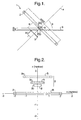
- FIG. 1 shows a schematic diagram, partly in section, of a magnetic resonance imaging (MRI) apparatus 1 in accordance with the present invention.
- MRI magnetic resonance imaging
- This comprises a first magnet in the form of a main coil 2.
- the main coil 2 in this case is in the form of a large flat ring, the diameter of the coil (between the central sections of opposing parts) is 4 metres with a height and width of the coil cross section itself being of the order of a few centimetres.
- the planes of the main and correction coils 2, 3 are arranged to be parallel with one another and the centres of the coils perpendicular to these planes are spaced by a set distance.
- the coils 2 and 3 each have a square cross section, although this is not essential.
- the rectangular side lengths of the coil sections are denoted by "2d”.
- the shape and area of the coil cross-sections vary between different coils.
- the radius of the coils is denoted by a value "r" which simply provides the radial distance between the geometric centre of the coil and centre of its section.
- r is 2 metres.
- the main and correction coils produce magnetic fields resulting in a substantially homogenous region which is suitable for MRI.
- a value "w" represents the distance between the geometric centre of a particular coil and that of the homogenous region.
- the substantially homogenous region in Figure 1 is shown at 5, having a diameter of 0.3 metres.
- a support 6 is also provided, typically this being in the form of a table upon which a patient (subject) may rest. As shown, the support is typically positioned horizontally and is located 0.2 metres beneath the centre of the substantially homogenous region 5.
- the main coil which produces most of the field has a mean diameter of 4 metres and the space available for the correction coils is determined by the working region, the support thickness and the angle "a" between the support and the axis of the coils.
- r 0 is a notional radius of the working volume and affects the sensitivity of the optimisation to the higher orders. Typically a value for r 0 in the range 0.05m to 0.1m was used.
- the minimisation software used steps down the "steepest slope" in the space of the parameters until one of four conditions is met, these being:
- the output of the abovementioned software was input into evaluation software which calculates the individual and total gradients and the numbers of ampere-turns for the resultant systems. The result of this can then be scanned for likely candidate systems.
- FIG. 2 A first example of a system according to the present invention is shown in Figure 2 .
- coordinate axes Z and X are shown.
- the main and correction coils 2,3 are arranged so as to have a common axis lying along the Z axis. It will be appreciated that although the X axis is indicated, the coils are symmetrical about the Z axis. It will also be noted that the origin of the coordinate axes lies at the centre of the main coil 2. In each of the following examples, the origin of the coordinate axes is arranged at the centre of the substantially homogeneous magnetic working region 5.
- the invention relates primarily to the arrangement of the magnets, other conventional support apparatus used for MRI imaging such as cryogenic apparatus, radio frequency (RF) emitters and detectors, signal processing systems, control systems and so on, are not described further here although would be present in practice.
- RF radio frequency
- the correction "coil” actually comprises three separate coils of various dimensions, these being labelled 3a,3b,3c. As indicated within Figure 2 , each of these coils have differing diameters and also have rectangular sections.
- coils of finite current density are mainly described by a1, a2, b, w, J.
- r is the radius of the centroid of the coil section and d is a dimension which characterises the width of the section.
- a1 is the outer radius of the coil section
- a2 is the inner radius
- b defines the width of the coil section along the Z axis, centred about the distance w from the centre of the substantively homogenous region 5.
- the relationship between the column numbers and the coils shown in Figure 2 can be determined by the distance "w" between the respective coil centre and the centre of the substantially homogeneous region 5.
- This system produced a rather large third order in the magnetic field and a relatively large hoop stress in coil 3a.
- the subject may be positioned such that the area of interest within the subject's body is precisely within the most uniform part of the substantially homogeneous region. This is particularly advantageous for imaging off-axis parts of a subject such as the shoulders.
- prior art systems it was necessary to produce a large enough substantially homogeneous region to encompass such an area. However, away from the centre of the region in such systems the field is less homogeneous than at the centre.
- the angled arrangement, the diameter of the main coil and the position of the correction coils also allows one or more medical personnel to be present during imaging, which provides for real-time imaging during medical procedures and interventions such as surgery.
- the fields produced in the working region 5 are sufficiently strong for such an application.
- Tissue such as tendons can also be oriented at an angle for imaging due to the open-access nature of the system.
- the coils 3a1, 3b1, 3c2 correspond to those labelled as 3a,3b,3c in Figure 2 .
- the reduction of the current density in coil 3c of the system of the first example resulted in a new system with coils 3b1 and 3c1 overlapping.
- the conductor requirement is 2.92 ⁇ 10 7 amp-m at 0.5 Tesla (of which the main coil represents 2.28 ⁇ 10 7 amp-m).
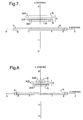
- FIG. 5 A fourth example of a system according to the invention is shown in Figure 5 .
- This has three correction coils 3a3,3b3,3c3 as indicated. Further details are given in Tables 6 and 7.
- Table 6 1 2 3 4 J 5.0000E+07 -1.9683E+08 -1.0185E+08 9.9476E+07 a 1 1.8960E+00 6.9000E-02 1.0370E+00 4.0400E-01 a 2 2.1040E+00 1.2700E-01 1.2080E+00 5.2300E-01 b 1.0400E-01 1.2500E-01 8.6000E-02 5.9000E-02 w 0.0000E+00 7.2500E-01 1.4700E+00 7.9431E-01 max B mod 4.115E+00 1.041E+01 6.980E+00 4.992E+00 max ⁇ h 3.687E+08 1.392E+08 6.991E+08 1.914E+08 min ⁇ h -3.060E+08 -
- the system of this example has good homogeneity. However, the stress in coil 3a3 is again quite high, and the peak field in coil 3c3 also ideally should have a lower current density. This system is however useful at a lower field, for example 0.25 Tesla.
- FIG. 6 A fifth example system is shown in Figure 6 .
- the Z axis is arranged upright as in the other figures.
- a sixth example is shown in Figure 7 with Tables 10 and 11 providing further details.
- 3 correction coils are used and in this particular case, the coil 3b5 (having current flowing in the same sense as the main coil 2) is closer to the centre of the working region 5 than the other correction coils 3a5, 3c5.
- This system shows good homogeneity but does exhibit high stress and a high field in coil 3b5. It is more suitably used as a 0.35T system for this reason. At this field strength, the conductor requirement is 4.7 ⁇ 10 7 amp-m.
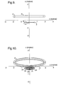
- FIG. 8 A seventh example is shown in Figure 8 . Again, of the three correction coils 3a6,3b6,3c6, the coil 3b6 is closest to the centre of the substantially homogeneous working region 5. Tables 12 and 13 provide further details. Table 12 1 2 3 4 J 5.0000E+07 1.0510E+08 -1.0406E+08 -1.0893E+08 a 1 1.9010E+00 4.5000E-01 5.9000E-01 1.1600E-01 a 2 2.0990E+00 6.5700E-01 7.7400E-01 3.3600E-01 b 9.9000E-02 5.5000E-02 7.7000E-02 9.0000E-02 w 0.0000E+00 6.9100E-01 8.7200E-01 1.0020E+00 max B mod 3.935E+00 9.439E+00 7.043E+00 1.455E+01 max ⁇ h 3.534E+08 2.103E+08 3.862E+08 1.888E+08 min ⁇ h -2.903E+08 -3
- This system has more tolerable stresses but has a high field in coil 3a6. It is appropriate as a 0.25T system.
- Figure 9 shows the main and correction coils when viewed from the side in a similar manner to the earlier examples. It will be noted in this case that the main coil lies "above" the correction coils. As earlier, the origin of the axes marks the position of the centre of the working region 5.
- the main coil 2 is again in the form of a ring having a diameter of 4 metres.
- five correction coils 3 are positioned beneath the main coil 2 upon a common axis Z.
- Each of the correction coils is of smaller diameter than the main coil 2 and has a small cross section.
- the correction coils are arranged approximately concentrically and are approximately regularly spaced in radial dimension.
- Figure 10 is a perspective view from a position such that the Z axis is tipped out of the plane of the figure.
- the circular shape of the coils is therefore visible, as are the individual correction coils, denoted 30,31,32,33,34.
- the middle coil 32 within the set has current passing through the coil in an opposite sense to the main coil 2.
- the other correction coils have currents running in a manner similar to the main coil 2.
- Figure 11 shows a view of the example along the Z axis.
- Tables 14 and 15 provide further details of the eighth example.
- Table 14 1 2 3 4 5 6 J 5.0000E+07 9.9315E+07 9.0467E+07 -1.0472E+08 9.8006E+07 1.0726E+08 a 1 1.4440E+00 1.0000E-01 2.0000E-01 3.0300E-01 3.9200E-01 5.0300E-01 a 2 1.5960E+00 1.0400E-01 2.1000E-01 3.1700E-01 4.1800E-01 5.1700E-01 b 7.6000E-02 2.0000E-03 4.0000E-03 6.0000E-03 1.1000E-02 8.0000E-03 w -4.0000E-01 2.0300E-01 2.0500E-01 2.1000E-01 2.1600E-01 2.1600E-01 max B mod 3.019E+00 6.414E-01 7.73TE-01 1.047E+00 1.364E+00 9.111E-01 max ⁇ h 2.060E+08 6.288E+06 1.
- the effect of the system according to this example is to substantially reduce the amount of cancellation necessary for the odd-order gradients in the magnetic field, and to move the correction coils closer to the field centre. In consequence, the correction coils are subject to lower fields and forces and so the system is more economical.
- the system shown according to the eighth example has six coils and this allows fourth order gradients to be cancelled so that the system can be somewhat smaller to achieve the same sized working region 5.
- Figure 12 shows an illustration of how a titled system such as that described in accordance with the fifth example can be used in practice.
- the main and correction coils 2,3 are shown, spaced apart, with a horizontal support 6 being positioned such that a subject lying upon the support has part of their body located at the geometric centre of the working region 5 (and the main coil 2 in this example).
- the correction coils 3 are partially sunken into the floor 7, as is one extreme end of the main coil 2. This allows for easy access to the working region 5 and the support 6.
- a figure representing one or more medical personnel is shown at 8 and it can be seen that such personnel can easily become positioned as indicated by entering the apparatus from the left of Figure 12 .
- Figure 13 illustrates a comparative example of a non-tilted system in accordance with the eighth example.
- the support 6 in the form of a bed
- the main coil 2 is provided at approximately the level of the upper chest of the medical personnel (allowing access by ducking under it). It can be seen that the working region lies upon the axis between the main 2 and correction coils 3, with the correction coils being positioned just beneath the support 6.
- a further, ninth, example is shown in Figure 14 .
- a main coil 2 is this time positioned beneath the origin of the co-ordinate axes (centred upon the working region 5).
- a set of correction coils 3 (totalling five in number) are provided above the origin. Four of these are approximately coplanar being centred at about 0.42 to 0.47 metres above the coordinate axes origin.
- Each of the coils is again arranged about a common axis 4 which, in Figure 14 , is tilted with respect to the Z axis in order to show the form of the coils.
- the fifth coil is positioned slightly above the other four coils at a distance of about 0.62 metres above the origin.
- This coil is labelled as 301, with the remaining coils being denoted as 311, 321, 331, and 341 as indicated in Figure 14 .
- these coils 301, 311, 341 and the main coil 2 each have current running within them in the same sense, with the current flowing in the opposite sense within coils 321 and 331.
- the main and correction coils 2, 3 are indicated, as is the support 6 upon which a subject lies in order to perform MRI.
- the working region is indicated at 5, positioned slightly above the support 6. This is shown more clearly in Figure 15 .
- Figure 15 shows the coils installed within a room having a floor 40 (indicated in Figure 15 ). Adjacent the support 6 is a region 41 within which one or more medical personnel are positioned during the operation of the system so as to perform interventions or procedures with respect to a subject lying upon the support 6.
- the support 6 is elongate in a direction normal to the plane of the Figure (that is normal to the z axis).
- the subject is therefore arranged end on with respect to Figure 15 .
- This arrangement provides a high level of open access which is particularly advantageous when combined with the large substantially homogeneous region resulting from the coil arrangement.
- Figure 16 shows the variation in the field gradient dB z /B 0 in the axial (Z axis) and radial direction.
- the radial trace is shown at 50 with the axial shown at 51 in Figure 16 . It can be seen that a substantially zero field gradient is produced over a large distance centred about the axis 4 of the system.
- Figure 17 shows the substantial homogeneity of the combined magnetic fields, resulting from the first and second magnets. It should be noted that the field inhomogeneities of one, three and ten parts per million (ppm) are each suitable for forming MRI imaging and therefore a large working region can be defined with high homogeneity at its centre.
- ppm parts per million
- Figure 18 is a schematic illustration of how such a tilted system may be used in practice.
- the axis 4 is tilted with respect to the vertical such that parts of the main and correction coils 2, 3 are embedded in the floor 40.
- An operator 8 representing one or more medical personnel is positioned within the region 41 shown in Figure 15 .
- the support table 6 is positioned laterally with respect to the main and correction coils such that the medical personnel can enter the system by walking through the main coil 2 to approach the support 6 (extending laterally with respect to the direction of approach).
- the correction coils 3 are therefore positioned behind the support 6.
- the substantially homogenous working region 5 is also indicated in Figure 18 .
- Support struts 50 along with part of the floor 40 support the respective forces caused by the interaction of the magnetic fields acting upon the respective main and correction coils 2, 3.
- Table 16 provides details of the dimensions of the coils in a similar manner to the previous examples with J being the current density in the amps per square metre.
- the row entitled “Amp-m” relates to the amount of superconducting material required for each coil. The peak magnetic field, axial force and minimum and maximum hoop stresses are also provided.
- Table 17 shows magnetic field derivatives of n th order where n is an integer from zero to 8. These are provided for the radial (B r ), tangential (B ⁇ ) and axial (B z ) components, with the sum (B mod ) also set out.
- This example therefore provides a particular advantage since open access is provided not only to the subject but also to the medical personnel because the correction coils 3 are positioned behind the support table 6.
- the gradients from these respective coils cooperate more favourably so as to produce a large homogenous working region 5.
- the nest of correction coils can therefore be placed closer to the support 6 which is beneficial in the number of ampere turns needed for a given combined field intensity and homogeniety.
Landscapes
- Physics & Mathematics (AREA)
- Electromagnetism (AREA)
- Condensed Matter Physics & Semiconductors (AREA)
- General Physics & Mathematics (AREA)
- Magnetic Resonance Imaging Apparatus (AREA)
Claims (23)
- Vorrichtung für Magnetresonanz-Bilderzeugung (1), die umfasst:einen ersten Magneten zum Erzeugen eines ersten Magnetfelds; undeinen zweiten Magneten zum Erzeugen eines zweiten Magnetfeldes, das dem ersten Magnetfeld nicht gleicht, wobei der zweite Magnet von dem ersten Magnet beabstandet ist;wobei der erste und der zweite Magnet jeweils eine oder mehrere Spulen (2, 3) umfassen und die Vorrichtung so eingerichtet ist, dass der erste und der zweite Magnet zusammenwirken, um ein im Wesentlichen homogenes Magnetfeld zu erzeugen, das einen Arbeitsbereich (5) definiert, das erste und das zweite Magnetfeld in Bezug auf den Arbeitsbereich (5) asymmetrisch angeordnet sind und wenigstens ein Teil des Arbeitsbereiches innerhalb des ersten Magneten oder zwischen dem ersten und dem zweiten Magneten positioniert ist,
wobei die Spulen (2, 3) des ersten und des zweiten Magneten entsprechende Ebenen definieren;
dadurch gekennzeichnet, dass:die Vorrichtung so eingerichtet ist, dass jede so definierte Ebene in Bezug auf die Horizontale angewinkelt ist und ein Teil der ersten Magnetspulen (2) in den Boden eines Ortes versenkt ist, an dem sich die Vorrichtung befindet, wobei die Abmessungen der ersten Magnetspulen (2) ausreichen, um es wenigstens einer Person zu gestatten, sich dem Arbeitsbereich (5) durch Laufen durch die ersten Magnetspulen (2) hindurch zu nähern, und um zu ermöglichen, dass die Person Vorgänge an einem Teil des Körpers einer Person durchführt, der in dem Arbeitsbereich (5) aufgenommen ist, wenn sich die Vorrichtung im Einsatz befindet. - Vorrichtung nach Anspruch 1, die im Einsatz so eingerichtet ist, dass bewirkt wird, dass elektrischer Strom in jeder der ersten Magnetspulen (2) in einer ersten Richtung (R) fließt, und wobei bewirkt wird, dass der Strom in wenigstens einer der Spulen (3) des zweiten Magneten in der ersten Richtung (R) und in wenigstens einer der anderen Spulen des zweiten Magneten in einer zweiten Richtung (B) fließt, die der ersten entgegengesetzt ist.
- Vorrichtung nach Anspruch 1 oder Anspruch 2, wobei der erste Magnet ein Haupt-Magnetfeld erzeugt und der zweite Magnet ein Korrektur-Magnetfeld erzeugt.
- Vorrichtung nach einem der Ansprüche 1 bis 3, wobei der erste und der zweite Magnet so beabstandet sind, dass sie ein Volumen definieren, die Mittelpunkte des ersten und des zweiten Magneten an den Grenzen des Volumens positioniert sind und wenigstens ein Teil des Arbeitsbereiches (5) innerhalb des Volumens positioniert ist.
- Vorrichtung nach Anspruch 4, wobei der Mittelpunkt des Arbeitsbereiches (5) innerhalb des Bereiches liegt, der das Volumen definiert.
- Vorrichtung nach einem der vorangehenden Ansprüche, wobei der zweite Magnet nur an einer Seite des Arbeitsbereiches (5) positioniert ist.
- Vorrichtung nach einem der Ansprüche 1 bis 5, wobei der erste Magnet nur an einer Seite des Arbeitsbereiches (5) positioniert ist.
- Vorrichtung nach einem der Ansprüche 1 bis 5, wobei der erste Magnet nur an einer ersten Seite des Arbeitsbereiches (5) positioniert ist, der zweite Magnet nur an einer zweiten Seite des Arbeitsbereiches vorhanden ist und die zweite Seite der ersten Seite in Bezug auf den Arbeitsbereich gegenüber liegt.
- Vorrichtung nach einem der Ansprüche 1 bis 6, wobei der Mittelpunkt des Arbeitsbereiches (5) am Mittelpunkt des ersten Magneten positioniert ist.
- Vorrichtung nach einem der vorangehenden Ansprüche, wobei das erste oder das zweite Magnetfeld oder beide in Bezug auf ihren Magneten asymmetrisch ist/sind.
- Vorrichtung nach einem der vorangehenden Ansprüche, wobei das erste und das zweite Magnetfeld zusammen ein resultierendes Magnetfeld erzeugen, das in Bezug auf den Arbeitsbereich (5) und/oder auf den ersten oder den zweiten Magneten oder beide asymmetrisch ist.
- Vorrichtung nach einem vorangehenden Ansprüche, wobei die Feldasymmetrie geometrische Asymmetrie bezüglich Stärke, Richtung und/oder Gradienten des Magnetfeldes ist.
- Vorrichtung nach einem der vorangehenden Ansprüche, wobei die Mittelpunkte des ersten und des zweiten Magneten und der Mittelpunkt des Arbeitsbereiches (5) auf einer gemeinsamen Achse (4) positioniert sind.
- Vorrichtung nach Anspruch 13, wobei der Durchmesser der ersten Spule die größte der Abmessungen ist, die die Spule definieren.
- Vorrichtung nach Anspruch 14, wobei die erste Spule einen Durchmesser von wenigstens 2 m hat.
- Vorrichtung nach Anspruch 15, wobei die erste Spule einen Durchmesser zwischen 2 und 4 m hat.
- Vorrichtung nach einem der vorangehenden Ansprüche, wobei der Winkel in Bezug auf die Horizontale 30°, 45°, 60° oder 90° beträgt.
- Vorrichtung nach Anspruch 17, wobei der Winkel weniger als 90° beträgt und die Vorrichtung so eingerichtet ist, dass der erste Magnet eine Hauptspule (2) umfasst, über die auf den Arbeitsbereich (5) zur Verwendung in einer Zugangsrichtung Zugang besteht, und wobei der zweite Magnet eine von mehreren Korrekturspulen (3) umfasst, die in der Zugangsrichtung hinter dem Arbeitsbereich positioniert sind.
- Vorrichtung nach einem der vorangehenden Ansprüche, die des Weiteren einen Träger (6) umfasst, auf den im Einsatz eine Person aufgelegt wird, um wenigstens einen Teil des Körpers der Person in dem Arbeitsbereich (5) zu positionieren.
- Vorrichtung nach Anspruch 19, wenn abhängig von Anspruch 18, wobei der Träger (6) in einer Längsrichtung länglich ist und die Längsrichtung im Wesentlichen senkrecht zu der Zugangsrichtung ist.
- Vorrichtung nach einem der vorangehenden Ansprüche, wobei einer oder jeder der Magneten Supraleitermagneten umfasst.
- Vorrichtung nach Anspruch 21, wobei die Supraleitermagneten Hochtemperatur-Supraleitermagneten sind.
- Vorrichtung nach einem der vorangehenden Ansprüche, die des Weiteren einen oder mehrere zusätzliche Magneten zum Erzeugen aktiver Abschirmung der Vorrichtung in Funktion umfasst.
Applications Claiming Priority (2)
| Application Number | Priority Date | Filing Date | Title |
|---|---|---|---|
| GB0309926 | 2003-04-30 | ||
| PCT/GB2004/001861 WO2004097443A1 (en) | 2003-04-30 | 2004-04-30 | Apparatus for magnetic resonance imaging |
Publications (2)
| Publication Number | Publication Date |
|---|---|
| EP1618403A1 EP1618403A1 (de) | 2006-01-25 |
| EP1618403B1 true EP1618403B1 (de) | 2009-01-14 |
Family
ID=33397033
Family Applications (1)
| Application Number | Title | Priority Date | Filing Date |
|---|---|---|---|
| EP04730583A Expired - Lifetime EP1618403B1 (de) | 2003-04-30 | 2004-04-30 | Kernspintomograph |
Country Status (5)
| Country | Link |
|---|---|
| US (1) | US7248048B2 (de) |
| EP (1) | EP1618403B1 (de) |
| JP (1) | JP2006525057A (de) |
| DE (1) | DE602004019069D1 (de) |
| WO (1) | WO2004097443A1 (de) |
Families Citing this family (4)
| Publication number | Priority date | Publication date | Assignee | Title |
|---|---|---|---|---|
| US7109708B2 (en) * | 2004-08-19 | 2006-09-19 | General Electric Company | Systems, methods and apparatus of a magnetic resonance imaging magnet to produce an asymmetrical stray field |
| US7466133B2 (en) | 2005-03-01 | 2008-12-16 | General Electric Company | Systems, methods and apparatus of a magnetic resonance imaging system to produce a stray field suitable for interventional use |
| GB0508890D0 (en) * | 2005-04-29 | 2005-06-08 | Oxford Instr Plc | Magnetic resonance apparatus and method |
| DE102007037851B4 (de) * | 2007-08-10 | 2012-08-09 | Siemens Ag | Bauteil mit schwingungsentkoppelter Verkleidung |
Family Cites Families (8)
| Publication number | Priority date | Publication date | Assignee | Title |
|---|---|---|---|---|
| US5250901A (en) * | 1991-11-07 | 1993-10-05 | The Regents Of The University Of California | Open architecture iron core electromagnet for MRI using superconductive winding |
| US5307039A (en) * | 1992-09-08 | 1994-04-26 | General Electric Company | Frustoconical magnet for magnetic resonance imaging |
| EP0766094B1 (de) | 1995-09-28 | 2002-05-29 | Siemens Aktiengesellschaft | Magnetanordnung für ein diagnostisches Magnetresonanzgerät |
| EP0797103B1 (de) * | 1996-03-28 | 1999-06-02 | Siemens Aktiengesellschaft | Magnetanordnung für die bildgebende magnetische Resonanz mit zwei getrennten Abbildungsvolumina |
| US5864236A (en) * | 1996-07-05 | 1999-01-26 | Toshiba America Mri, Inc. | Open configuration MRI magnetic flux path |
| US6255929B1 (en) | 1998-03-23 | 2001-07-03 | The Board Of Trustees Of The Leland Stanford Junior University | Method of making optimized, air-core electromagnets |
| JP4004661B2 (ja) * | 1998-09-11 | 2007-11-07 | 株式会社日立メディコ | 磁気共鳴イメージング装置 |
| US6064290A (en) | 1999-05-21 | 2000-05-16 | The Board Of Trustees Of The Leland Stanford Junior University | Short bore-length asymmetric electromagnets for magnetic resonance imaging |
-
2004
- 2004-04-30 EP EP04730583A patent/EP1618403B1/de not_active Expired - Lifetime
- 2004-04-30 US US10/554,940 patent/US7248048B2/en not_active Expired - Fee Related
- 2004-04-30 DE DE602004019069T patent/DE602004019069D1/de not_active Expired - Fee Related
- 2004-04-30 WO PCT/GB2004/001861 patent/WO2004097443A1/en not_active Ceased
- 2004-04-30 JP JP2006506204A patent/JP2006525057A/ja not_active Abandoned
Also Published As
| Publication number | Publication date |
|---|---|
| US20060202695A1 (en) | 2006-09-14 |
| WO2004097443A1 (en) | 2004-11-11 |
| DE602004019069D1 (de) | 2009-03-05 |
| US7248048B2 (en) | 2007-07-24 |
| EP1618403A1 (de) | 2006-01-25 |
| JP2006525057A (ja) | 2006-11-09 |
Similar Documents
| Publication | Publication Date | Title |
|---|---|---|
| TWI743481B (zh) | 用於磁共振成像系統的b磁鐵方法及設備 | |
| US5659281A (en) | Structured coil electromagnets for magnetic resonance imaging | |
| EP1893290B1 (de) | Teilchen-strahlentherapieausrüstung mit einem magnetresonanz-bildgebungsmittel | |
| CA2960194C (en) | Ferromagnetic augmentation for magnetic resonance imaging | |
| US6396376B1 (en) | Apparatus and method for a superconductive magnet with pole piece | |
| US6373251B1 (en) | Nuclear magnetic resonance apparatus and methods of use and facilities for incorporating the same | |
| EP0441862B1 (de) | Anordnung zur erzeugung eines magnetischen feldes | |
| US12591028B2 (en) | Resistive electromagnet systems and methods | |
| CN111913142B (zh) | 基本场磁体装置、磁共振断层造影系统和测量方法 | |
| EP0414528B1 (de) | Ferromagnetische Kompensationsringe für Magnete hoher Feldstärke | |
| US5345208A (en) | Pole face design for a C-shaped superconducting magnet | |
| US5117188A (en) | Quasi-open magnet configuration for use in magnetic resonance imaging | |
| US9689952B2 (en) | Magnetic resonance system with pulsed compensation magnetic field gradients | |
| US6853855B2 (en) | Magnetic resonance tomography apparatus with improved spatial and time stabilization of the homogeneity of the magnetic basic field | |
| Chen et al. | Electromagnetic computation and modeling in MRI | |
| US7193417B2 (en) | Bi-planar coil assemblies for producing specified magnetic fields | |
| US4931759A (en) | Magnetic resonance imaging magnet having minimally symmetric ferromagnetic shield | |
| EP1618403B1 (de) | Kernspintomograph | |
| JP6392141B2 (ja) | 磁場均一度調整方法、磁場均一度調整プログラムおよび磁場均一度調整装置 | |
| US5431164A (en) | Therapy tomograph | |
| US7898257B2 (en) | Open yoke magnet assembly | |
| EP1546750B1 (de) | Anordnung und verfahren zur magnetfelderzeugung | |
| EP1457788A2 (de) | Gepulster Auslesemagnet für die bildgebende magnetische Resonanz | |
| EP0629872A1 (de) | Supraleitender Magnet in C-Form | |
| JPH0580903B2 (de) |
Legal Events
| Date | Code | Title | Description |
|---|---|---|---|
| PUAI | Public reference made under article 153(3) epc to a published international application that has entered the european phase |
Free format text: ORIGINAL CODE: 0009012 |
|
| 17P | Request for examination filed |
Effective date: 20051116 |
|
| AK | Designated contracting states |
Kind code of ref document: A1 Designated state(s): AT BE BG CH CY CZ DE DK EE ES FI FR GB GR HU IE IT LI LU MC NL PL PT RO SE SI SK TR |
|
| AX | Request for extension of the european patent |
Extension state: AL HR LT LV MK |
|
| DAX | Request for extension of the european patent (deleted) | ||
| RBV | Designated contracting states (corrected) |
Designated state(s): DE FR GB NL |
|
| 17Q | First examination report despatched |
Effective date: 20071029 |
|
| GRAP | Despatch of communication of intention to grant a patent |
Free format text: ORIGINAL CODE: EPIDOSNIGR1 |
|
| GRAS | Grant fee paid |
Free format text: ORIGINAL CODE: EPIDOSNIGR3 |
|
| GRAA | (expected) grant |
Free format text: ORIGINAL CODE: 0009210 |
|
| AK | Designated contracting states |
Kind code of ref document: B1 Designated state(s): DE FR GB NL |
|
| REG | Reference to a national code |
Ref country code: GB Ref legal event code: FG4D |
|
| REF | Corresponds to: |
Ref document number: 602004019069 Country of ref document: DE Date of ref document: 20090305 Kind code of ref document: P |
|
| PGFP | Annual fee paid to national office [announced via postgrant information from national office to epo] |
Ref country code: NL Payment date: 20090405 Year of fee payment: 6 Ref country code: FR Payment date: 20090417 Year of fee payment: 6 Ref country code: DE Payment date: 20090428 Year of fee payment: 6 |
|
| PLBE | No opposition filed within time limit |
Free format text: ORIGINAL CODE: 0009261 |
|
| STAA | Information on the status of an ep patent application or granted ep patent |
Free format text: STATUS: NO OPPOSITION FILED WITHIN TIME LIMIT |
|
| PGFP | Annual fee paid to national office [announced via postgrant information from national office to epo] |
Ref country code: GB Payment date: 20090429 Year of fee payment: 6 |
|
| 26N | No opposition filed |
Effective date: 20091015 |
|
| REG | Reference to a national code |
Ref country code: NL Ref legal event code: V1 Effective date: 20101101 |
|
| GBPC | Gb: european patent ceased through non-payment of renewal fee |
Effective date: 20100430 |
|
| REG | Reference to a national code |
Ref country code: FR Ref legal event code: ST Effective date: 20101230 |
|
| PG25 | Lapsed in a contracting state [announced via postgrant information from national office to epo] |
Ref country code: NL Free format text: LAPSE BECAUSE OF NON-PAYMENT OF DUE FEES Effective date: 20101101 |
|
| PG25 | Lapsed in a contracting state [announced via postgrant information from national office to epo] |
Ref country code: DE Free format text: LAPSE BECAUSE OF NON-PAYMENT OF DUE FEES Effective date: 20101103 |
|
| PG25 | Lapsed in a contracting state [announced via postgrant information from national office to epo] |
Ref country code: GB Free format text: LAPSE BECAUSE OF NON-PAYMENT OF DUE FEES Effective date: 20100430 |
|
| PG25 | Lapsed in a contracting state [announced via postgrant information from national office to epo] |
Ref country code: FR Free format text: LAPSE BECAUSE OF NON-PAYMENT OF DUE FEES Effective date: 20100430 |